EP1445509A1 - Internal combustion engine with balancer shaft and method of assembling the same - Google Patents
Internal combustion engine with balancer shaft and method of assembling the same Download PDFInfo
- Publication number
- EP1445509A1 EP1445509A1 EP04001732A EP04001732A EP1445509A1 EP 1445509 A1 EP1445509 A1 EP 1445509A1 EP 04001732 A EP04001732 A EP 04001732A EP 04001732 A EP04001732 A EP 04001732A EP 1445509 A1 EP1445509 A1 EP 1445509A1
- Authority
- EP
- European Patent Office
- Prior art keywords
- balancer shaft
- balancer
- flattened section
- internal combustion
- combustion engine
- Prior art date
- Legal status (The legal status is an assumption and is not a legal conclusion. Google has not performed a legal analysis and makes no representation as to the accuracy of the status listed.)
- Granted
Links
- 238000002485 combustion reaction Methods 0.000 title claims abstract description 25
- 238000000034 method Methods 0.000 title claims abstract description 11
- 238000009434 installation Methods 0.000 claims description 13
- 230000005484 gravity Effects 0.000 claims description 4
- 238000013016 damping Methods 0.000 description 2
- 230000000694 effects Effects 0.000 description 2
- 230000004323 axial length Effects 0.000 description 1
- 238000012986 modification Methods 0.000 description 1
- 230000004048 modification Effects 0.000 description 1
- 230000001743 silencing effect Effects 0.000 description 1
Images


Classifications
-
- F—MECHANICAL ENGINEERING; LIGHTING; HEATING; WEAPONS; BLASTING
- F16—ENGINEERING ELEMENTS AND UNITS; GENERAL MEASURES FOR PRODUCING AND MAINTAINING EFFECTIVE FUNCTIONING OF MACHINES OR INSTALLATIONS; THERMAL INSULATION IN GENERAL
- F16C—SHAFTS; FLEXIBLE SHAFTS; ELEMENTS OR CRANKSHAFT MECHANISMS; ROTARY BODIES OTHER THAN GEARING ELEMENTS; BEARINGS
- F16C3/00—Shafts; Axles; Cranks; Eccentrics
- F16C3/02—Shafts; Axles
-
- F—MECHANICAL ENGINEERING; LIGHTING; HEATING; WEAPONS; BLASTING
- F16—ENGINEERING ELEMENTS AND UNITS; GENERAL MEASURES FOR PRODUCING AND MAINTAINING EFFECTIVE FUNCTIONING OF MACHINES OR INSTALLATIONS; THERMAL INSULATION IN GENERAL
- F16F—SPRINGS; SHOCK-ABSORBERS; MEANS FOR DAMPING VIBRATION
- F16F15/00—Suppression of vibrations in systems; Means or arrangements for avoiding or reducing out-of-balance forces, e.g. due to motion
- F16F15/22—Compensation of inertia forces
- F16F15/26—Compensation of inertia forces of crankshaft systems using solid masses, other than the ordinary pistons, moving with the system, i.e. masses connected through a kinematic mechanism or gear system
- F16F15/264—Rotating balancer shafts
-
- Y—GENERAL TAGGING OF NEW TECHNOLOGICAL DEVELOPMENTS; GENERAL TAGGING OF CROSS-SECTIONAL TECHNOLOGIES SPANNING OVER SEVERAL SECTIONS OF THE IPC; TECHNICAL SUBJECTS COVERED BY FORMER USPC CROSS-REFERENCE ART COLLECTIONS [XRACs] AND DIGESTS
- Y10—TECHNICAL SUBJECTS COVERED BY FORMER USPC
- Y10T—TECHNICAL SUBJECTS COVERED BY FORMER US CLASSIFICATION
- Y10T29/00—Metal working
- Y10T29/49—Method of mechanical manufacture
- Y10T29/49229—Prime mover or fluid pump making
- Y10T29/49231—I.C. [internal combustion] engine making
Definitions
- the present invention relates to an internal combustion engine with a balancer shaft and a method of assembling the same.
- a balancer housing is disposed under an engine block.
- a drive side balancer shaft and driven side drive balancer shaft having respective eccentric weight portions are disposed within the balancer housing so as to be parallel with a crankshaft and rotatable in timed relation with each other.
- a power transmitting mechanism including a pair of sprockets and a chain for transmitting rotation of the crankshaft to the drive side balancer shaft.
- one of the sprockets is installed on the end portion of the crankshaft and the other is installed on the end portion of the drive side balancer shaft. Then, the chain is wound around the sprockets and thereafter the tension of the chain is adjusted by a chain guide and a tensioner.
- crankshaft and the balancer shaft in place and installing the power transmitting mechanism so as to attain a desired timed relation between them requires a quite complicated work due to a conventional layout.
- an internal combustion engine comprising a balancer housing, a balancer shaft having an eccentric weight portion and disposed within the balancer housing so as to be parallel with and rotatable in timed relation to a crankshaft, and a power transmitting mechanism that transmits rotation of the crankshaft to the balancer shaft, wherein the balancer shaft has an end portion protruding outward of the balancer housing, and wherein the end portion of the balancer shaft is partially cut to have a flattened section that constitutes a device for positioning the balancer shaft in a predetermined rotational position.
- a method of assembling an internal combustion engine with a balancer shaft comprising disposing within a balancer housing a balancer shaft having an eccentric weight portion so as to be parallel with and rotatable in timed relation with a crankshaft, providing the balancer shaft with an end portion protruding outward of the balancer housing, partly cutting the end portion of the balancer shaft to form a flattened section used for positioning of the balancer shaft, providing the balancer housing with a roof-like arcuated protrusion that is opposed to the flattened section in the radial direction of the balancer shaft, and fitting a U-shaped jaw of a tool on the flattened section and the roof-like arcuated protrusion and thereby positioning the balancer shaft in a predetermined rotational position.
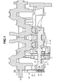
- an in-line four-cylinder internal combustion engine includes engine block 1, crankshaft 2 rotatably installed on a lower portion of engine block 1 and balancer housing 3 disposed under crankshaft 2. Disposed within balancer housing 3 in parallel with crankshaft 2 are drive side and driven (follower) side balancer shafts 4, 5 having eccentric balancer weight portions 4a.
- Balancer shafts 4, 5 have reverse gears (not shown) that are meshed with each other so as to rotate in opposite directions. By this, rotation of drive side balancer shaft 4 causes driven side balancer shaft 5 to rotate in timed relation thereto.
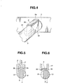
- Drive side balancer shaft 4 has an end portion (i.e. a left-hand end side end portion in FIG. 1) 6 that protrudes outward of balancer housing 3. End portion 6 is partly cut so as to form flattened section 8 used for positioning of balancer shaft 4. More specifically, end portion 6 is cut at diametrically opposite sections so that flattened section 8 have parallel flat surfaces 18, 19 which are unequally distant from a center axis of balancer shaft 4 as shown in FIGS. 4 to 6.
- Right-hand flat surface 18 that is positioned on the leading side with respect to a clockwise rotation of balancer shaft 4 when observed in FIGS. 4 to 6 is formed larger than left-hand flat surface 19 that is position on the trailing side.
- flattened section 8 is asymmetrical about the center axis of balancer shaft 4 so as to serve as an eccentric balancer weight section that cooperates with eccentric balancer weight portions 4a to assist a balancing operation thereof, i.e., flattened section 8 is formed so as to have, when observed in cross section, a center of gravity or geometrical center that is offset from the center of balancer shaft 4 in the same direction as eccentric balancer weight portions 4a.
- Balancer housing 3 has at one side thereof a roof-like arcuated protrusion 9 that is opposed to flattened section 8 in the radial direction of balancer shaft 4.
- Roof-like arcuated protrusion 9 is of such a cross section that is asymmetrical about the center axis of balancer shaft 4. When observed in cross section shown in FIG. 5, flattened section 8 and roof-like protrusion 9 are substantially equal in width.
- the distance between opposite end surfaces 9a, 9b of roof-like protrusion 9 is substantially equal to the distance between flat surfaces 18, 19 of balancer shaft 4 so that opposite end surfaces 9a, 9b of roof-like arcuate protrusion 9 are coplanar with respective flat surfaces 18, 19 of flattened section 8 when balancer shaft 4 is in a predetermined rotational or phase position.
- flat surfaces 18, 19 of flattened section 8 and opposite end surfaces 9a, 9b of roof-like arcuated protrusion 9 are nearly positioned on respective common vertical planes as shown in FIG. 4.
- flattened section 8 and roof-like arcuated protrusion 9 are of such axial lengths that can be gripped by a U-shaped jaw of tool 17, e.g., 20 to 30 mm in length.
- the U-shaped jaw of tool 17 can fittingly grip flattened section 8 of drive side balancer shaft 4 and roof-like arcuated protrusion 9 only when flattened section 8 is in a correct rotational or phase position (i.e., when flat surfaces 18, 19 of flattened section 8 and opposite end surfaces 9a, 9b of roof-like arcuated protrusion 9 are nearly positioned on respective common vertical planes).
- a power transmitting mechanism 10 including sprockets 11, 12 and chain 13 is installed on end portions of crankshaft 2 and balancer shaft 4.
- Driven side balancer shaft 5 is shorter than drive side balancer shaft 4 and drivingly connected at an end to oil pump 7 so as to drive the same.
- Oil pump 7 is supported by balancer housing 3.
- the tooth striking sound produced by reverse gears respectively provided to balancer shafts 4, 5 can be suppressed by a damping effect (silencing effect) produced by oil pump 7.
- driven side balancer shaft 5 is adapted to rotate at double the speed of crankshaft 2, so that oil pump 7 can discharge a sufficient amount of oil and therefore can be smaller in size.
- crankshaft 2 and drive side balancer shaft 4 To end portions of crankshaft 2 and drive side balancer shaft 4 (the left-hand end portions in FIG. 1) is installed power transmitting mechanism 10 by way of which balancer shaft 4 is driven by crankshaft 2.
- Power transmitting mechanism 10 includes crank sprocket 11 adapted to be installed on crankshaft 2, balancer sprocket 12 adapted to be installed on drive side balancer shaft 4 and chain 13 wound around sprockets 11, 12.
- flattened section 8 of drive side balancer shaft 4 and roof-like arcuated protrusion 9 of balancer housing 3 are gripped by the U-shaped jaw of tool 17 under the condition where flattened section 8 corresponds in the rotational phase to roof-like arcuate protrusion 9, thus preventing drive side balancer shaft 4 from rotating relative to balancer housing 3 and therefore engine block 1 (refer to FIGS. 3 to 5).
- the U-shaped jaw of tool 17 has a gripping width that is equal to or a little larger than the width of flattened section 8 of drive side balancer shaft 4 (i.e., the distance between flat surfaces 18, 19) and roof-like arcuate protrusion 9 of balancer housing 3 (i.e., the distance between end surfaces 9a, 9b).
- drive side balancer shaft 4 can be located in a predetermined rotational or phase position (refer to FIG. 5).
- crank sprocket 11 and balancer sprocket 12 of power transmitting mechanism 10 are fixedly attached to crankshaft 2 and drive side balancer shaft 4, respectively.
- balancer sprocket 12 is secured to drive side balancer shaft 4 by sprocket bolt 16.
- flattened section 8 and roof-like arcuate protrusion 9 are asymmetrical about the center axis of drive side balancer shaft 4, a correct rotational or phase position of flattened section 8 of drive side balancer shaft 4 can be one, thus making it possible to carry out installation of power transmitting mechanism 10 under a condition where drive side balancer shaft 4 is held at a predetermine rotational or phase position.
- balancer housing 3 has roof-like arcuate protrusion 9 that is opposed to flattened section 8 in the radial direction of balancer shaft 4 and that cooperates with flattened section 8 of balancer shaft 4 to constitute the device for positioning balancer shaft 4 in the predetermined rotational or phase position.
- roof-shaped arcuated protrusion 9 of balancer housing 3 is gripped by tool 17 together with flattened section 8 of balancer shaft 4, thus making it possible to perform an installation work with ease.
- flattened section 8 is formed asymmetrical about the center axis of balancer shaft 4 or flattened section 8s is formed so as to have a center of gravity that is offset from the center of balancer shaft 4. Due to this, the phase position of drive side balancer shaft 4 relative to roof-shaped arcuate protrusion 9 can be only one (i.e., a correct phase position), thus enabling tool 17 to grip flattened section 8 only when drive side balancer shaft 4 is in a correct rotational or phase position. On the other hand, in case flattened section 8 of drive side balancer shaft 4 is in a reverse phase position, tool 17 cannot grip flattened section 8. Accordingly, rotating balancer shaft 4 into a predetermined rotational or phase position can be attained with ease and it becomes possible to prevent balancer shaft 4 from being installed at a phase position that is shifted from a correct phase position by 180 degrees.
- flattened section 8 of balancer shaft 4 has flat surfaces 18, 19 and is shaped asymmetrical about the center axis of balancer shaft 4 so that one of flat surfaces 18, 19 that is positioned on the leading side with respect to clockwise rotation of balancer shaft 4 when observed in FIG. 5 is larger than flat surface 19 that is positioned on the trailing side.
- balancer sprocket 12 In installation of balancer sprocket 12 to drive side balancer shaft 4 by holding balancer shaft 4 stationarily in a predetermined position (i.e., correct phase position) by tool 17, larger flat surface 18 is urged against the corresponding surface of tool 17 when balancer sprocket 12 is screwed to the end portion of balancer shaft 4 with sprocket bolt 16 of right-hand thread, thus enabling balancer shaft 4 to have a sufficient strength.
- flattened section 8 is asymmetrical about the center axis of balancer shaft 4 or so shaped as to have, when observed in cross section, a center of gravity or geometrical center that is offset in the direction to cooperate with eccentric weight portions 4a of balancer shaft 4 to perform a balancing action. Due to this, rotation of flattened section 8 can suppress a secondary vibration of the engine, thus enabling eccentric weight portion 4a to be smaller.
- driven side balancer shaft 5 that is not directly driven by power transmitting mechanism 10 is drivingly connected to oil pump 7 to drive the same. Due to this, by the damping effect produced by oil pump 7, the tooth striking sound that is produced by meshing of the reverse gears of drive side and driven side balancer shafts 4, 5 due to backlash can be suppressed.
Landscapes
- Engineering & Computer Science (AREA)
- General Engineering & Computer Science (AREA)
- Mechanical Engineering (AREA)
- Physics & Mathematics (AREA)
- Acoustics & Sound (AREA)
- Aviation & Aerospace Engineering (AREA)
- Ocean & Marine Engineering (AREA)
- Shafts, Cranks, Connecting Bars, And Related Bearings (AREA)
- Lubrication Of Internal Combustion Engines (AREA)
- Cylinder Crankcases Of Internal Combustion Engines (AREA)
Abstract
Description
- The present invention relates to an internal combustion engine with a balancer shaft and a method of assembling the same.
- An internal combustion engine with a pair of balancer shafts is disclosed in Japanese Patent Provisional Publication No. 6-33989. In the engine, a balancer housing is disposed under an engine block. A drive side balancer shaft and driven side drive balancer shaft having respective eccentric weight portions are disposed within the balancer housing so as to be parallel with a crankshaft and rotatable in timed relation with each other. Between the crankshaft and the drive side balancer shaft is disposed a power transmitting mechanism including a pair of sprockets and a chain for transmitting rotation of the crankshaft to the drive side balancer shaft.
- Namely, one of the sprockets is installed on the end portion of the crankshaft and the other is installed on the end portion of the drive side balancer shaft. Then, the chain is wound around the sprockets and thereafter the tension of the chain is adjusted by a chain guide and a tensioner.
- In installation of the power transmitting mechanism on the crankshaft and the balancer shaft, it is necessitated to make them operate in such a timed relation that can reduce or suppress a secondary vibration of the engine generated by a reciprocating motion of pistons.
- However, positioning the crankshaft and the balancer shaft in place and installing the power transmitting mechanism so as to attain a desired timed relation between them requires a quite complicated work due to a conventional layout.
- It is accordingly an object of the present invention to provide an internal combustion engine with a balancer shaft that enables a power transmitting mechanism to be installed on a crankshaft and a balancer shaft with an easier work.
- To achieve the above object, there is provided according to an aspect of the present invention an internal combustion engine comprising a balancer housing, a balancer shaft having an eccentric weight portion and disposed within the balancer housing so as to be parallel with and rotatable in timed relation to a crankshaft, and a power transmitting mechanism that transmits rotation of the crankshaft to the balancer shaft, wherein the balancer shaft has an end portion protruding outward of the balancer housing, and wherein the end portion of the balancer shaft is partially cut to have a flattened section that constitutes a device for positioning the balancer shaft in a predetermined rotational position.
- There is provided according to another aspect of the present invention a method of assembling an internal combustion engine with a balancer shaft comprising disposing within a balancer housing a balancer shaft having an eccentric weight portion so as to be parallel with and rotatable in timed relation with a crankshaft, providing the balancer shaft with an end portion protruding outward of the balancer housing, partly cutting the end portion of the balancer shaft to form a flattened section used for positioning of the balancer shaft, providing the balancer housing with a roof-like arcuated protrusion that is opposed to the flattened section in the radial direction of the balancer shaft, and fitting a U-shaped jaw of a tool on the flattened section and the roof-like arcuated protrusion and thereby positioning the balancer shaft in a predetermined rotational position.
-
- FIG. 1 is a sectional view of an important portion of an internal combustion engine with a pair of balancer shafts according to an embodiment of the present invention;
- FIG. 2 is a side elevational view of the internal combustion engine of FIG. 1;
- FIG. 3 is a perspective view of the internal combustion engine of FIG. 1 though the engine is shown in a state of being turned upside down;
- FIG. 4 is a perspective view of a flattened section of a drive side balancer shaft and a roof-like arcuated protrusion of a balancer housing employed in the internal combustion engine of FIG. 1;
- FIG. 5 is a cross sectional view of the flattened section and the roof-like arcuated protrusion of FIG. 4, together with a tool fitted on the flattened section and the roof-like arcuated protrusion; and
- FIG. 6 is a view similar to FIG. 5 but shows the flattened section and the roof-like arcuate protrusion in a state resulting when the drive side balancer shaft is in a phase position moved from a proper phase position by 180 degrees.
-
- Referring to FIGS. 1 to 6, inclusive, an in-line four-cylinder internal combustion engine includes engine block 1,
crankshaft 2 rotatably installed on a lower portion of engine block 1 and balancerhousing 3 disposed undercrankshaft 2. Disposed withinbalancer housing 3 in parallel withcrankshaft 2 are drive side and driven (follower)side balancer shafts balancer weight portions 4a. -
Balancer shafts side balancer shaft 4 causes drivenside balancer shaft 5 to rotate in timed relation thereto. - Drive
side balancer shaft 4 has an end portion (i.e. a left-hand end side end portion in FIG. 1) 6 that protrudes outward ofbalancer housing 3.End portion 6 is partly cut so as to formflattened section 8 used for positioning ofbalancer shaft 4. More specifically,end portion 6 is cut at diametrically opposite sections so thatflattened section 8 have parallelflat surfaces balancer shaft 4 as shown in FIGS. 4 to 6. Right-handflat surface 18 that is positioned on the leading side with respect to a clockwise rotation ofbalancer shaft 4 when observed in FIGS. 4 to 6 is formed larger than left-handflat surface 19 that is position on the trailing side. In this connection,flattened section 8 is asymmetrical about the center axis ofbalancer shaft 4 so as to serve as an eccentric balancer weight section that cooperates with eccentricbalancer weight portions 4a to assist a balancing operation thereof, i.e.,flattened section 8 is formed so as to have, when observed in cross section, a center of gravity or geometrical center that is offset from the center ofbalancer shaft 4 in the same direction as eccentricbalancer weight portions 4a. By this, whencrankshaft 2 and balancershafts flattened section 8 can reduce or suppress a secondary vibration of the engine in cooperation with eccentricbalancer weight portions 4a ofbalancer shaft 4. -
Balancer housing 3 has at one side thereof a roof-like arcuatedprotrusion 9 that is opposed toflattened section 8 in the radial direction ofbalancer shaft 4. Roof-like arcuatedprotrusion 9 is of such a cross section that is asymmetrical about the center axis ofbalancer shaft 4. When observed in cross section shown in FIG. 5,flattened section 8 and roof-like protrusion 9 are substantially equal in width. Namely, the distance betweenopposite end surfaces like protrusion 9 is substantially equal to the distance betweenflat surfaces balancer shaft 4 so thatopposite end surfaces arcuate protrusion 9 are coplanar with respectiveflat surfaces flattened section 8 whenbalancer shaft 4 is in a predetermined rotational or phase position. Whenbalancer shaft 4 is in a correct rotational or phase position,flat surfaces flattened section 8 andopposite end surfaces protrusion 9 are nearly positioned on respective common vertical planes as shown in FIG. 4. In the meantime,flattened section 8 and roof-like arcuatedprotrusion 9 are of such axial lengths that can be gripped by a U-shaped jaw oftool 17, e.g., 20 to 30 mm in length. - The U-shaped jaw of
tool 17 can fittingly gripflattened section 8 of driveside balancer shaft 4 and roof-like arcuatedprotrusion 9 only whenflattened section 8 is in a correct rotational or phase position (i.e., whenflat surfaces flattened section 8 andopposite end surfaces protrusion 9 are nearly positioned on respective common vertical planes). Under the condition where the U-shaped jaw oftool 17 grips flattenedsection 8 and roof-likearcuate protrusion 9 for thereby preventingbalancer shaft 4 from rotating, apower transmitting mechanism 10 includingsprockets chain 13 is installed on end portions ofcrankshaft 2 andbalancer shaft 4. Further, in installation ofpower transmitting mechanism 10, an installation work is performed while holding engine block 1 in a state of its side to be attached to a cylinder block (not shown) being disposed on the lower side as shown in FIG. 3. This makes it possible to perform the installation work ofpower transmitting mechanism 10 without the necessity of holdingtool 17 by hands aftertool 17 is fitted onflattened section 8 and roof-like arcuatedprotrusion 9. - Driven
side balancer shaft 5 is shorter than driveside balancer shaft 4 and drivingly connected at an end tooil pump 7 so as to drive the same.Oil pump 7 is supported bybalancer housing 3. By this, the tooth striking sound produced by reverse gears respectively provided to balancershafts oil pump 7. Further, drivenside balancer shaft 5 is adapted to rotate at double the speed ofcrankshaft 2, so thatoil pump 7 can discharge a sufficient amount of oil and therefore can be smaller in size. - To end portions of
crankshaft 2 and drive side balancer shaft 4 (the left-hand end portions in FIG. 1) is installedpower transmitting mechanism 10 by way of whichbalancer shaft 4 is driven bycrankshaft 2. -
Power transmitting mechanism 10 includescrank sprocket 11 adapted to be installed oncrankshaft 2,balancer sprocket 12 adapted to be installed on driveside balancer shaft 4 andchain 13 wound aroundsprockets - Then, installation of
power transmitting mechanism 10 oncrankshaft 2 and driveside balancer shaft 4 will be described. - Firstly,
flattened section 8 of driveside balancer shaft 4 and roof-like arcuatedprotrusion 9 ofbalancer housing 3 are gripped by the U-shaped jaw oftool 17 under the condition whereflattened section 8 corresponds in the rotational phase to roof-likearcuate protrusion 9, thus preventing driveside balancer shaft 4 from rotating relative to balancerhousing 3 and therefore engine block 1 (refer to FIGS. 3 to 5). - In this connection, the U-shaped jaw of
tool 17 has a gripping width that is equal to or a little larger than the width offlattened section 8 of drive side balancer shaft 4 (i.e., the distance betweenflat surfaces 18, 19) and roof-likearcuate protrusion 9 of balancer housing 3 (i.e., the distance betweenend surfaces tool 17 onflattened section 8 and roof-likearcuate protrusion 9 under the condition whereflattened section 8 and roof-likearcuate protrusion 9 correspond in phase to each other (i.e.,flat surfaces flattened section 8 are nearly coplanar withopposite end surfaces arcuate protrusion 9, respectively), driveside balancer shaft 4 can be located in a predetermined rotational or phase position (refer to FIG. 5). - Then,
crank sprocket 11 and balancersprocket 12 ofpower transmitting mechanism 10 are fixedly attached tocrankshaft 2 and driveside balancer shaft 4, respectively. In this instance,balancer sprocket 12 is secured to driveside balancer shaft 4 bysprocket bolt 16. - In the meantime, if the phase of
flattened section 8 of driveside balancer shaft 4 differs from a correct phase position by 180 degrees as shown in FIG. 6,tool 17 cannot be fitted on flattened section and roof-like protrusion 9. - As having been described above, since
flattened section 8 and roof-likearcuate protrusion 9 are asymmetrical about the center axis of driveside balancer shaft 4, a correct rotational or phase position offlattened section 8 of driveside balancer shaft 4 can be one, thus making it possible to carry out installation ofpower transmitting mechanism 10 under a condition where driveside balancer shaft 4 is held at a predetermine rotational or phase position. - In the foregoing, it will be understood that according to the present invention, only one of a plurality of
balancer shafts power transmitting mechanism 10 is provided withend portion 6 protruding outward ofbalancer housing 3, whichend portion 6 is partly cut to formflattened section 8 that constitutes a device forpositioning balancer shaft 4 in a predetermined rotational or phase position. In installation ofcrank sprocket 11 and balancersprocket 12 ofpower transmitting mechanism 10,flattened section 8 of driveside balancer shaft 4 can be gripped bytool 17 and thereby located in a predetermined phase position, thus making it possible to perform an installation work under a condition ofbalancer shaft 4 being prevented from rotation. Particularly, a work for securingbalancer sprocket 12 to driveside balancer shaft 4 by means ofsprocket bolt 16 can be done with ease. - It will be further understood that according to the present invention, balancer
housing 3 has roof-likearcuate protrusion 9 that is opposed toflattened section 8 in the radial direction ofbalancer shaft 4 and that cooperates withflattened section 8 ofbalancer shaft 4 to constitute the device forpositioning balancer shaft 4 in the predetermined rotational or phase position. In installation ofpower transmitting mechanism 10, roof-shapedarcuated protrusion 9 ofbalancer housing 3 is gripped bytool 17 together withflattened section 8 ofbalancer shaft 4, thus making it possible to perform an installation work with ease. - It will be further understood that according to the present invention,
flattened section 8 is formed asymmetrical about the center axis ofbalancer shaft 4 or flattened section 8s is formed so as to have a center of gravity that is offset from the center ofbalancer shaft 4. Due to this, the phase position of driveside balancer shaft 4 relative to roof-shapedarcuate protrusion 9 can be only one (i.e., a correct phase position), thus enablingtool 17 to gripflattened section 8 only when driveside balancer shaft 4 is in a correct rotational or phase position. On the other hand, in caseflattened section 8 of driveside balancer shaft 4 is in a reverse phase position,tool 17 cannot gripflattened section 8. Accordingly, rotatingbalancer shaft 4 into a predetermined rotational or phase position can be attained with ease and it becomes possible to preventbalancer shaft 4 from being installed at a phase position that is shifted from a correct phase position by 180 degrees. - It will be further understood that according to the present invention, flattened
section 8 ofbalancer shaft 4 hasflat surfaces balancer shaft 4 so that one offlat surfaces balancer shaft 4 when observed in FIG. 5 is larger thanflat surface 19 that is positioned on the trailing side. In installation ofbalancer sprocket 12 to driveside balancer shaft 4 by holdingbalancer shaft 4 stationarily in a predetermined position (i.e., correct phase position) bytool 17, largerflat surface 18 is urged against the corresponding surface oftool 17 whenbalancer sprocket 12 is screwed to the end portion ofbalancer shaft 4 withsprocket bolt 16 of right-hand thread, thus enablingbalancer shaft 4 to have a sufficient strength. - It will be further understood that according to the present invention, flattened
section 8 is asymmetrical about the center axis ofbalancer shaft 4 or so shaped as to have, when observed in cross section, a center of gravity or geometrical center that is offset in the direction to cooperate witheccentric weight portions 4a ofbalancer shaft 4 to perform a balancing action. Due to this, rotation of flattenedsection 8 can suppress a secondary vibration of the engine, thus enablingeccentric weight portion 4a to be smaller. - It will be further understood that according to the present invention, driven
side balancer shaft 5 that is not directly driven bypower transmitting mechanism 10 is drivingly connected tooil pump 7 to drive the same. Due to this, by the damping effect produced byoil pump 7, the tooth striking sound that is produced by meshing of the reverse gears of drive side and drivenside balancer shafts - The entire contents of Japanese Patent Applications P2003-029738(filed February 6, 2003) are incorporated herein by reference.
- Although the invention has been described above by reference to a certain embodiment of the invention, the invention is not limited to the embodiment described above. Modifications and variations of the embodiment described above will occur to those skilled in the art, in light of the above teachings. The scope of the invention is defined with reference to the following claims.
Claims (18)
- An internal combustion engine comprising:wherein the balancer shaft (4) has an end portion (6) protruding outward of the balancer housing (3); anda balancer housing (3);a balancer shaft (4) having an eccentric weight portion (4a) and disposed within the balancer housing (3) so as to be parallel with and rotatable in timed relation with a crankshaft (2); anda power transmitting mechanism (10) that transmits rotation of the crankshaft (2) to the balancer shaft (4);
wherein the end portion (6) of the balancer shaft (4) is partially cut to have a flattened section (8) that constitutes a device for positioning the balancer shaft (4) in a predetermined rotational position. - An internal combustion engine according to claim 1, wherein the balancer housing (3) has a roof-like arcuated protrusion (9) that is opposed to the flattened section (8) in the radial direction of the balancer shaft (4) and that cooperates with the flattened section (8) of the balancer shaft (4) to constitute the device for positioning the balancer shaft (4) in the predetermined rotational position.
- An internal combustion engine according to claim 2, wherein the roof-like arcuated protrusion (9) is asymmetrical about a center axis of the balancer shaft (4).
- An internal combustion engine according to any of claims 1 to 3, wherein the flattened section (8) is asymmetrical about a center axis of the balancer shaft (4).
- An internal combustion engine according to any of claims 1 to 4, wherein the flattened section (8) has a pair of parallel flat surfaces (18, 19) that are diametrically opposed to each other and unequally distant from the center axis of the balancer shaft (4).
- An internal combustion engine according to claim 5, wherein one of the flat surfaces (18, 19) that is located on a leading side with respect to a direction in which the balancer shaft is urged to rotate upon installation of the power transmitting mechanism on the balancer shaft (4) is larger than the other of the flat surfaces (18, 19).
- An internal combustion engine according to any of claims 1 to 6, wherein the power transmitting mechanism (10) comprises a balancer sprocket (12) that is screwed to an end portion of the balancer shaft (4) with a bolt (16).
- An internal combustion engine according to claim 5 or 6, wherein the roof-like arcuate protrusion (9) has opposite end surfaces (9a, 9b), the distance between which is substantially equal to that between the flat surfaces (18, 19) of the balancer shaft (4) so that the opposite end surfaces (9a, 9b) of the roof-like arcuate protrusion (9) are coplanar with the respective flat surfaces (18, 19) of the flattened section (8) of the balancer shaft (4) when the balancer shaft is in the predetermined rotational position.
- An internal combustion engine according to any of claims 1 to 8, wherein the flattened section (8) is shaped so as to have a center of gravity that is offset from the center axis of the balancer shaft (4) in the direction to assist a balancing operation of the eccentric weight portion (4a) of the balancer shaft (4).
- An internal combustion engine according to claim 1, further comprising a second balancer shaft (5) that is disposed in parallel with the first-mentioned balancer shaft (4) and indirectly driven by the power transmitting mechanism (10), the second balancer shaft (5) being drivingly connected to an oil pump (7).
- An internal combustion engine according to claim 1, wherein the power transmitting mechanism (10) further comprises a crank sprocket (11) installed on an end portion of the crankshaft (2), a balancer sprocket (12) installed on an end portion of the balancer shaft (4) and a chain (13) wound around the crank sprocket (11) and the balancer sprocket (12).
- A method of assembling an internal combustion engine with a balancer shaft (4) comprising:disposing within a balancer housing (3) a balancer shaft (4) having an eccentric weight portion (4a) so as to be parallel with and rotatable in timed relation with a crankshaft (2);providing the balancer shaft (4) with an end portion (6) protruding outward of the balancer housing (3);partly cutting the end portion (6) of the balancer shaft (4) to form a flattened section (8) used for positioning of the balancer shaft (4);providing the balancer housing (3) with a roof-like arcuated protrusion that is opposed to the flattened section (8) in the radial direction of the balancer shaft (4); andfitting a U-shaped jaw of a tool (17) on the flattened section (8) and the roof-like arcuated protrusion (9) and thereby positioning the balancer shaft (4) in a predetermined rotational position.
- A method according to claim 12, wherein the roof-like arcuated protrusion (9) is asymmetrical about a center axis of the balancer shaft (4).
- A method according to claim 12 or 13, wherein the flattened section is asymmetrical about a center axis of the balancer shaft.
- A method according to any of claims 12 to 14, wherein the flattened section (8) has a pair of parallel flat surfaces (18, 19) that are diametrically opposed to each other and unequally distant from the center axis of the balancer shaft (4).
- A method according to claim 15, wherein one (18) of the flat surfaces that is located on a leading side with respect to a direction in which the balancer shaft (4) is urged to rotate upon installation of the power transmitting mechanism (10) on the balancer shaft (4) is larger than the other (19) of the flat surfaces.
- A method according to any of claims 12 to 16, wherein the power transmitting mechanism (10) comprises a balancer sprocket (12) that is screwed to an end portion of the balancer shaft (4) with a bolt (16).
- A method according to claim 15 or 16, wherein the roof-like arcuate protrusion (9) has opposite end surfaces (9a, 9b), the distance between which is substantially equal to that between the flat surfaces (18, 19) of the balancer shaft (4) so that the opposite end surfaces (9a, 9b) of the roof-like arcuate protrusion (9) are coplanar with the respective flat surfaces (18, 19) of the flattened section (8) of the balancer shaft (4) when the balancer shaft is in the predetermined rotational position.
Applications Claiming Priority (2)
| Application Number | Priority Date | Filing Date | Title |
|---|---|---|---|
| JP2003029738 | 2003-02-06 | ||
| JP2003029738A JP3807376B2 (en) | 2003-02-06 | 2003-02-06 | Engine with balancer shaft and method of assembling the same |
Publications (2)
| Publication Number | Publication Date |
|---|---|
| EP1445509A1 true EP1445509A1 (en) | 2004-08-11 |
| EP1445509B1 EP1445509B1 (en) | 2005-12-21 |
Family
ID=32652998
Family Applications (1)
| Application Number | Title | Priority Date | Filing Date |
|---|---|---|---|
| EP04001732A Expired - Lifetime EP1445509B1 (en) | 2003-02-06 | 2004-01-27 | Internal combustion engine with balancer shaft and method of assembling the same |
Country Status (6)
| Country | Link |
|---|---|
| US (1) | US6868816B2 (en) |
| EP (1) | EP1445509B1 (en) |
| JP (1) | JP3807376B2 (en) |
| KR (1) | KR100585362B1 (en) |
| CN (1) | CN100402885C (en) |
| DE (1) | DE602004000239T2 (en) |
Cited By (2)
| Publication number | Priority date | Publication date | Assignee | Title |
|---|---|---|---|---|
| FR2885661A1 (en) | 2005-05-12 | 2006-11-17 | Renault Soc Par Actions Simpli | THERMAL MOTOR COMPRISING BALANCING SHAFTS THAT CAN BE IMMOBILIZED BY A PIN |
| GB2493271A (en) * | 2011-07-26 | 2013-01-30 | Honda Motor Co Ltd | An internal combustion engine with a balancer |
Families Citing this family (15)
| Publication number | Priority date | Publication date | Assignee | Title |
|---|---|---|---|---|
| JP4297860B2 (en) * | 2004-09-29 | 2009-07-15 | 本田技研工業株式会社 | Small planing boat internal combustion engine |
| JP4614724B2 (en) * | 2004-09-29 | 2011-01-19 | 本田技研工業株式会社 | Small planing boat internal combustion engine |
| JP4573610B2 (en) * | 2004-09-29 | 2010-11-04 | 本田技研工業株式会社 | Small planing boat internal combustion engine |
| JP4439368B2 (en) * | 2004-09-29 | 2010-03-24 | 本田技研工業株式会社 | Small planing boat internal combustion engine |
| JP4587371B2 (en) * | 2004-10-27 | 2010-11-24 | ヤマハ発動機株式会社 | Parallel multi-cylinder four-cycle engine and saddle riding type vehicle |
| US7252060B2 (en) * | 2005-07-14 | 2007-08-07 | Borgwarner Inc | Torsional damper for balance shafts |
| JP2007040340A (en) * | 2005-08-01 | 2007-02-15 | Toyota Industries Corp | Crank shaft of v-type six-cylinder engine |
| DE102008063315B4 (en) * | 2008-01-10 | 2013-08-22 | Magna Powertrain Ag & Co. Kg | Mass balance unit |
| JP5000611B2 (en) * | 2008-09-17 | 2012-08-15 | 日立オートモティブシステムズ株式会社 | Balancer device for internal combustion engine |
| KR101040337B1 (en) * | 2008-12-01 | 2011-06-10 | 기아자동차주식회사 | Balance shaft mounting system |
| EP2494235B1 (en) * | 2009-10-27 | 2019-05-29 | Metaldyne BSM, LLC | Method and apparatus for securing a balancer shaft module |
| US8468995B2 (en) * | 2010-05-17 | 2013-06-25 | GM Global Technology Operations LLC | Compact second order balance shaft arrangement with low inertia driven shaft |
| JP5748601B2 (en) * | 2011-08-03 | 2015-07-15 | 日立オートモティブシステムズ株式会社 | Balancer device for internal combustion engine and method for determining improper assembly of balancer device |
| JP7412463B2 (en) * | 2022-01-28 | 2024-01-12 | ダイハツ工業株式会社 | internal combustion engine |
| WO2024142758A1 (en) * | 2022-12-28 | 2024-07-04 | 日立Astemo株式会社 | Balancer device for internal combustion engine |
Citations (4)
| Publication number | Priority date | Publication date | Assignee | Title |
|---|---|---|---|---|
| GB2117837A (en) * | 1982-03-30 | 1983-10-19 | Ford Motor Co | Internal combustion engine with mass balancing |
| US4665766A (en) * | 1983-09-28 | 1987-05-19 | Nippon Piston Ring Co., Ltd. | Shaft member |
| EP0809041A2 (en) * | 1996-05-20 | 1997-11-26 | Audi Ag | Means for equilibration of inertial torque in internal combustion engines |
| DE19754687A1 (en) * | 1997-12-10 | 1999-06-17 | Volkswagen Ag | Balance shaft, preferably for a reciprocating piston internal combustion engine |
Family Cites Families (2)
| Publication number | Priority date | Publication date | Assignee | Title |
|---|---|---|---|---|
| JP3206114B2 (en) | 1992-07-17 | 2001-09-04 | 日産自動車株式会社 | Engine with balancer shaft |
| JP3371892B2 (en) | 1993-09-22 | 2003-01-27 | 日産自動車株式会社 | Balancer device for internal combustion engine |
-
2003
- 2003-02-06 JP JP2003029738A patent/JP3807376B2/en not_active Expired - Lifetime
-
2004
- 2004-01-27 EP EP04001732A patent/EP1445509B1/en not_active Expired - Lifetime
- 2004-01-27 DE DE602004000239T patent/DE602004000239T2/en not_active Expired - Lifetime
- 2004-02-02 US US10/768,634 patent/US6868816B2/en not_active Expired - Lifetime
- 2004-02-05 KR KR1020040007394A patent/KR100585362B1/en not_active Expired - Lifetime
- 2004-02-06 CN CNB2004100036828A patent/CN100402885C/en not_active Expired - Lifetime
Patent Citations (4)
| Publication number | Priority date | Publication date | Assignee | Title |
|---|---|---|---|---|
| GB2117837A (en) * | 1982-03-30 | 1983-10-19 | Ford Motor Co | Internal combustion engine with mass balancing |
| US4665766A (en) * | 1983-09-28 | 1987-05-19 | Nippon Piston Ring Co., Ltd. | Shaft member |
| EP0809041A2 (en) * | 1996-05-20 | 1997-11-26 | Audi Ag | Means for equilibration of inertial torque in internal combustion engines |
| DE19754687A1 (en) * | 1997-12-10 | 1999-06-17 | Volkswagen Ag | Balance shaft, preferably for a reciprocating piston internal combustion engine |
Cited By (9)
| Publication number | Priority date | Publication date | Assignee | Title |
|---|---|---|---|---|
| FR2885661A1 (en) | 2005-05-12 | 2006-11-17 | Renault Soc Par Actions Simpli | THERMAL MOTOR COMPRISING BALANCING SHAFTS THAT CAN BE IMMOBILIZED BY A PIN |
| WO2007003812A2 (en) | 2005-05-12 | 2007-01-11 | Renault S.A.S. | Heat engine comprising balance shafts which can be locked by a pin |
| WO2007003812A3 (en) * | 2005-05-12 | 2007-03-08 | Renault Sa | Heat engine comprising balance shafts which can be locked by a pin |
| CN101171439B (en) * | 2005-05-12 | 2010-09-22 | 雷诺股份公司 | heat engine including a pinned balance shaft |
| RU2400656C2 (en) * | 2005-05-12 | 2010-09-27 | Рено С.А.С. | Ice with balancing shafts that can be cotter-pined and method of mounting balancing cassette on ice unit |
| US7921825B2 (en) | 2005-05-12 | 2011-04-12 | Renault S.A.S. | Engine comprising balance shafts locked by a pin |
| GB2493271A (en) * | 2011-07-26 | 2013-01-30 | Honda Motor Co Ltd | An internal combustion engine with a balancer |
| US9157365B2 (en) | 2011-07-26 | 2015-10-13 | Honda Motor Co., Ltd. | Internal combustion engine with balancer |
| GB2493271B (en) * | 2011-07-26 | 2018-05-30 | Honda Motor Co Ltd | Internal combustion engine with balancer |
Also Published As
| Publication number | Publication date |
|---|---|
| JP3807376B2 (en) | 2006-08-09 |
| KR100585362B1 (en) | 2006-06-01 |
| JP2004239360A (en) | 2004-08-26 |
| DE602004000239T2 (en) | 2006-07-06 |
| DE602004000239D1 (en) | 2006-01-26 |
| EP1445509B1 (en) | 2005-12-21 |
| US20040154575A1 (en) | 2004-08-12 |
| KR20040071633A (en) | 2004-08-12 |
| US6868816B2 (en) | 2005-03-22 |
| CN1519489A (en) | 2004-08-11 |
| CN100402885C (en) | 2008-07-16 |
Similar Documents
| Publication | Publication Date | Title |
|---|---|---|
| US6868816B2 (en) | Internal combustion engine with balancer shaft and method of assembling the same | |
| EP1347159B1 (en) | Engine | |
| EP3524794B1 (en) | A reciprocating piston mechanism | |
| US8720403B2 (en) | Having a crankshaft and two balancer shafts | |
| US8590509B2 (en) | Speed governor of engine | |
| JP4024022B2 (en) | Crankshaft phasing structure | |
| US6332440B1 (en) | Four-stroke cycle internal combustion engine | |
| JP4373195B2 (en) | Engine balancer equipment | |
| US7506627B2 (en) | Balancer shaft arrangement for engine | |
| JP5000611B2 (en) | Balancer device for internal combustion engine | |
| US7159558B2 (en) | Engine having centralized mass | |
| CN1603655A (en) | Gear assembly structure | |
| JP2005325834A (en) | Internal combustion engine | |
| JP3539196B2 (en) | Driving force transmission device | |
| JPH09329193A (en) | Backlash adjustment method in engine balancer device | |
| JP2001271883A (en) | Balancer shaft structure of internal combustion engine | |
| JP2915329B2 (en) | Lubricating device for two-cycle engine | |
| WO2022138359A1 (en) | General-purpose engine starting device, and general-purpose engine | |
| JPH11325184A (en) | Engine balancer | |
| DE60335056D1 (en) | ||
| JPH04203638A (en) | Engine main parts driver | |
| JPH01240738A (en) | Drive mechanism of auxiliary machine in internal combustion engine | |
| JPH0320139A (en) | Internal combustion engine balancer device | |
| KR19990005202A (en) | Balance shaft drive of engine | |
| KR19990005203A (en) | Balance shaft drive of engine |
Legal Events
| Date | Code | Title | Description |
|---|---|---|---|
| PUAI | Public reference made under article 153(3) epc to a published international application that has entered the european phase |
Free format text: ORIGINAL CODE: 0009012 |
|
| 17P | Request for examination filed |
Effective date: 20040127 |
|
| AK | Designated contracting states |
Kind code of ref document: A1 Designated state(s): AT BE BG CH CY CZ DE DK EE ES FI FR GB GR HU IE IT LI LU MC NL PT RO SE SI SK TR |
|
| AX | Request for extension of the european patent |
Extension state: AL LT LV MK |
|
| 17Q | First examination report despatched |
Effective date: 20050221 |
|
| AKX | Designation fees paid |
Designated state(s): DE FR GB |
|
| GRAP | Despatch of communication of intention to grant a patent |
Free format text: ORIGINAL CODE: EPIDOSNIGR1 |
|
| GRAS | Grant fee paid |
Free format text: ORIGINAL CODE: EPIDOSNIGR3 |
|
| GRAA | (expected) grant |
Free format text: ORIGINAL CODE: 0009210 |
|
| AK | Designated contracting states |
Kind code of ref document: B1 Designated state(s): DE FR GB |
|
| REG | Reference to a national code |
Ref country code: GB Ref legal event code: FG4D |
|
| REF | Corresponds to: |
Ref document number: 602004000239 Country of ref document: DE Date of ref document: 20060126 Kind code of ref document: P |
|
| ET | Fr: translation filed | ||
| PLBE | No opposition filed within time limit |
Free format text: ORIGINAL CODE: 0009261 |
|
| STAA | Information on the status of an ep patent application or granted ep patent |
Free format text: STATUS: NO OPPOSITION FILED WITHIN TIME LIMIT |
|
| 26N | No opposition filed |
Effective date: 20060922 |
|
| REG | Reference to a national code |
Ref country code: FR Ref legal event code: PLFP Year of fee payment: 13 |
|
| REG | Reference to a national code |
Ref country code: FR Ref legal event code: PLFP Year of fee payment: 14 |
|
| REG | Reference to a national code |
Ref country code: FR Ref legal event code: PLFP Year of fee payment: 15 |
|
| PGFP | Annual fee paid to national office [announced via postgrant information from national office to epo] |
Ref country code: FR Payment date: 20230119 Year of fee payment: 20 |
|
| PGFP | Annual fee paid to national office [announced via postgrant information from national office to epo] |
Ref country code: GB Payment date: 20230120 Year of fee payment: 20 Ref country code: DE Payment date: 20230119 Year of fee payment: 20 |
|
| REG | Reference to a national code |
Ref country code: DE Ref legal event code: R071 Ref document number: 602004000239 Country of ref document: DE |
|
| REG | Reference to a national code |
Ref country code: GB Ref legal event code: PE20 Expiry date: 20240126 |
|
| PG25 | Lapsed in a contracting state [announced via postgrant information from national office to epo] |
Ref country code: GB Free format text: LAPSE BECAUSE OF EXPIRATION OF PROTECTION Effective date: 20240126 |