EP1445495A1 - Engineered flexure component - Google Patents
Engineered flexure component Download PDFInfo
- Publication number
- EP1445495A1 EP1445495A1 EP03029150A EP03029150A EP1445495A1 EP 1445495 A1 EP1445495 A1 EP 1445495A1 EP 03029150 A EP03029150 A EP 03029150A EP 03029150 A EP03029150 A EP 03029150A EP 1445495 A1 EP1445495 A1 EP 1445495A1
- Authority
- EP
- European Patent Office
- Prior art keywords
- grooves
- interface
- flexures
- flexure
- engineered
- Prior art date
- Legal status (The legal status is an assumption and is not a legal conclusion. Google has not performed a legal analysis and makes no representation as to the accuracy of the status listed.)
- Granted
Links
Images


Classifications
-
- F—MECHANICAL ENGINEERING; LIGHTING; HEATING; WEAPONS; BLASTING
- F16—ENGINEERING ELEMENTS AND UNITS; GENERAL MEASURES FOR PRODUCING AND MAINTAINING EFFECTIVE FUNCTIONING OF MACHINES OR INSTALLATIONS; THERMAL INSULATION IN GENERAL
- F16F—SPRINGS; SHOCK-ABSORBERS; MEANS FOR DAMPING VIBRATION
- F16F15/00—Suppression of vibrations in systems; Means or arrangements for avoiding or reducing out-of-balance forces, e.g. due to motion
- F16F15/02—Suppression of vibrations of non-rotating, e.g. reciprocating systems; Suppression of vibrations of rotating systems by use of members not moving with the rotating systems
- F16F15/04—Suppression of vibrations of non-rotating, e.g. reciprocating systems; Suppression of vibrations of rotating systems by use of members not moving with the rotating systems using elastic means
-
- F—MECHANICAL ENGINEERING; LIGHTING; HEATING; WEAPONS; BLASTING
- F16—ENGINEERING ELEMENTS AND UNITS; GENERAL MEASURES FOR PRODUCING AND MAINTAINING EFFECTIVE FUNCTIONING OF MACHINES OR INSTALLATIONS; THERMAL INSULATION IN GENERAL
- F16F—SPRINGS; SHOCK-ABSORBERS; MEANS FOR DAMPING VIBRATION
- F16F7/00—Vibration-dampers; Shock-absorbers
- F16F7/08—Vibration-dampers; Shock-absorbers with friction surfaces rectilinearly movable along each other
-
- G—PHYSICS
- G02—OPTICS
- G02B—OPTICAL ELEMENTS, SYSTEMS OR APPARATUS
- G02B23/00—Telescopes, e.g. binoculars; Periscopes; Instruments for viewing the inside of hollow bodies; Viewfinders; Optical aiming or sighting devices
- G02B23/16—Housings; Caps; Mountings; Supports, e.g. with counterweight
-
- Y—GENERAL TAGGING OF NEW TECHNOLOGICAL DEVELOPMENTS; GENERAL TAGGING OF CROSS-SECTIONAL TECHNOLOGIES SPANNING OVER SEVERAL SECTIONS OF THE IPC; TECHNICAL SUBJECTS COVERED BY FORMER USPC CROSS-REFERENCE ART COLLECTIONS [XRACs] AND DIGESTS
- Y10—TECHNICAL SUBJECTS COVERED BY FORMER USPC
- Y10T—TECHNICAL SUBJECTS COVERED BY FORMER US CLASSIFICATION
- Y10T428/00—Stock material or miscellaneous articles
- Y10T428/24—Structurally defined web or sheet [e.g., overall dimension, etc.]
- Y10T428/24479—Structurally defined web or sheet [e.g., overall dimension, etc.] including variation in thickness
- Y10T428/2457—Parallel ribs and/or grooves
Definitions
- This invention relates to an engineered flexure component used at the bolted interfaces of precision optical instruments.
- a bolt flange is provided with parallel grooves across its surface.
- One bolt flange surface has grooves that run in a vertical direction
- a second bolt flange surface has grooves that run in a horizontal direction, such that they are perpendicular to the grooves of the first bolt flange mating surface.
- the purpose of the grooves is to create a surface that consists of flexures. These flexures cause two effects to occur at the bolted interface. First, for a given clamping force, the resulting surface pressure is greater because of the smaller contact area at the interface which in turn increases the friction force. Second, the flexures are sufficiently flexible enough to bend and not slide as the two interface surfaces move relative to each other.
- the flexure points may different configurations, i.e.
- load path management is a process by which a designer can control the effect of friction by not effecting the frictional mechanisms, but by changing the elastic stiffness that surrounds the frictional element. Placing grooves in the interface mating surfaces enables a designer to model the interface stiffness as a series of bending beams, which in turn allows the designer to explicitly model the percentage of force that acts through friction.
- a bolt flange 10 having a front surface 105.
- Bolt flange 10 is provided with parallel grooves 110 which transverse front surface 105.
- grooves 110 transverse front surface 105 in a vertical direction.
- front surface 105' of a second bolt flange has grooves 110' which transverse front surface 105' in a horizontal direction, such that they are perpendicular to grooves 110 of the first bolt flange front surface 105 when the first and second bolt flanges are bolted together creating an interface.
- grooves 110, 110' The purpose of grooves 110, 110' is to create a flexure 115, 115'.
- Flexures 115, 115' cause two effects to occur at a bolted interface. First, for a given clamping force, the resulting surface pressure is greater because of the smaller contact area at the interface which in turn increases the coulombic friction force. Second, flexures 115, 115' provide additional flexibility such that the percentage of force transmitted across the interface is reduced.
- the width and height of flexures 115, 115' is determined by the flexure bending stiffness, flexure axial stiffness, flexure tortional stiffness, flexure buckling limit and load path management design rules.
- Fig. 2 is an alternative embodiment in which grooves 110" transverse front surface 105" in both the vertical and horizontal directions, creating a cross-hatched appearance. As shown in Fig. 4, this embodiment is used when the bolt flange comes into with a flat, smooth surface.
- the flexure points may have different configurations, i.e. squares, circles, triangles, or other geometric shapes.
- Load path management theory states that it is possible to reduce or tailor the effect of interface friction by effecting the elastic mechanisms that surround the friction element. Due to the dependency that hysteresis has on the relative magnitudes of stiffness at an interface, load path management states that it is possible to reduce the dissipation due to friction at an interface not by affecting the friction mechanism, but by changing the relative magnitudes of stiffness. This can be achieved by changing the design of the interface to increase the percentage of load transferred through internal elastic mechanisms.
- the non-conservative segment of the model represents a combination of elastic and friction mechanisms that exist in a non-conservative load path.
- the hysteretic mechanism of the interface is represented by a Coulombic friction mechanism which is in parallel with a linear spring element (k p ) as well as in series with another linear spring element (k s ).
- a Coulombic friction mechanism was chosen because it represents the hysteretic mechanics that exist at an interface.
- a linear, elastic mechanism (k e ) in parallel with the non-conservative load path represents the conservative load path at an interface.
- the analytical model of Fig. 4 represents such an interface.
- This interface model illustrates how an externally applied load (F a ) may be divided into elastic (i.e. normal) and inelastic (i.e.
- the k e elastic element of the model represents the elastic behavior of the body from the application of the external load to normal stress at the interface.
- the k s elastic mechanism of the model represents the elastic behavior of the body from the application of the external load to shear stress at the interface.
- Load transfer across the interface is represented by an elastic mechanism (k p ) in parallel with the friction mechanism ⁇ N.
- the elastic mechanism k p represents the portion of the shear load that is transferred across an interface elastically, i.e. regions within the contact area where slip does not occur.
- the friction mechanism represents the portion of the shear load that is transferred across an interface inelastically, i.e. regions within the contact area where slip does occur.
- the engineered flexure component of the present invention involves changing the value of k s , the elastic spring constant associated with the elastic behavior of the body from the application of the external load to the shear stress at the interface. Reducing the spring stiffness k s reduces the percentage of force that acts through elastic mechanisms. This changing of the local interface between the mating surfaces of structural elements allows the mating surfaces to return to their original position because the flexure points bend, but do not slide with respect to each other.
Landscapes
- Engineering & Computer Science (AREA)
- General Engineering & Computer Science (AREA)
- Physics & Mathematics (AREA)
- Mechanical Engineering (AREA)
- Optics & Photonics (AREA)
- Aviation & Aerospace Engineering (AREA)
- Astronomy & Astrophysics (AREA)
- General Physics & Mathematics (AREA)
- Acoustics & Sound (AREA)
- Connection Of Plates (AREA)
- Springs (AREA)
- Telescopes (AREA)
- Bolts, Nuts, And Washers (AREA)
- Dowels (AREA)
- Bearings For Parts Moving Linearly (AREA)
- Clamps And Clips (AREA)
Abstract
Description
- This invention relates to an engineered flexure component used at the bolted interfaces of precision optical instruments.
- For precision structures, such as telescopes, it is important to understand the sources of mechanical hysteresis, which is defined as the dependence of the strain of a material not only on the instantaneous value of the stress, but also on the previous history of the stress. It is known that whenever two structural elements are bolted together, friction exists at the bolted interface. Bolted interfaces are a source of both damping and instability. Friction may be the cause of energy dissipation as the two surfaces slide past one another as well as cause the two mating surfaces to slide and stop in a new position relative to each other. At present, interface designers cannot explicitly control the percentages of forces that act across an interface through friction. Currently, many optic mounts for precision optical instruments are bolted directly to an optical bench. In a high vibrational environment, the optic mounts tend to react to external forces and reposition themselves, thus causing the optical instrument to shift their position. Given the foregoing, there is a need for an engineered flexure component that is sufficiently flexible enough to bend and not slide as the mating surfaces of the bolted interface move relative to each other.
- A bolt flange is provided with parallel grooves across its surface. One bolt flange surface has grooves that run in a vertical direction, while a second bolt flange surface has grooves that run in a horizontal direction, such that they are perpendicular to the grooves of the first bolt flange mating surface. The purpose of the grooves is to create a surface that consists of flexures. These flexures cause two effects to occur at the bolted interface. First, for a given clamping force, the resulting surface pressure is greater because of the smaller contact area at the interface which in turn increases the friction force. Second, the flexures are sufficiently flexible enough to bend and not slide as the two interface surfaces move relative to each other. The flexure points may different configurations, i.e. squares, circles, triangles, or other geometric shapes. The grooving of the surfaces allows a designer of optical instruments to be capable of determining the stiffness of the resulting flexure as well as control the percentages of forces that are transferred across an interface through friction as compared with elastic bending. The flexured interface also allows the designer to invoke load path management design rules. In summary, load path management is a process by which a designer can control the effect of friction by not effecting the frictional mechanisms, but by changing the elastic stiffness that surrounds the frictional element. Placing grooves in the interface mating surfaces enables a designer to model the interface stiffness as a series of bending beams, which in turn allows the designer to explicitly model the percentage of force that acts through friction.
-
- Fig. 1 is a perspective view of the engineered flexure component of the present invention;
- Fig. 2 is a perspective view of an alternative embodiment to the engineered flexure component of Fig. 1;
- Fig. 3 is an exploded view of a flexured assembly utilizing the embodiment shown in Fig.1;
- Fig. 4 is an exploded view of a flexured assembly utilizing the alternative embodiment shown in Fig. 2;
- Fig. 5 is a model showing the force transfer in both the conservative and non-conservative load paths that may exist at the interface of a flexured assembly and
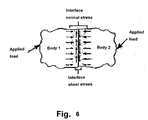
- Fig. 6 is an illustration of the load paths that exist across the interface of a flexured assembly.
-
- Referring to the drawings, and in particular, Fig. 1, there is provided a
bolt flange 10 having afront surface 105.Bolt flange 10 is provided withparallel grooves 110 which transversefront surface 105. As shown in Fig. 1,grooves 110 transversefront surface 105 in a vertical direction. As shown in Fig. 3, front surface 105' of a second bolt flange has grooves 110' which transverse front surface 105' in a horizontal direction, such that they are perpendicular to grooves 110 of the first boltflange front surface 105 when the first and second bolt flanges are bolted together creating an interface. - The purpose of
grooves 110, 110' is to create aflexure 115, 115'.Flexures 115, 115' cause two effects to occur at a bolted interface. First, for a given clamping force, the resulting surface pressure is greater because of the smaller contact area at the interface which in turn increases the coulombic friction force. Second,flexures 115, 115' provide additional flexibility such that the percentage of force transmitted across the interface is reduced. The width and height offlexures 115, 115' is determined by the flexure bending stiffness, flexure axial stiffness, flexure tortional stiffness, flexure buckling limit and load path management design rules. - Fig. 2 is an alternative embodiment in which grooves 110"
transverse front surface 105" in both the vertical and horizontal directions, creating a cross-hatched appearance. As shown in Fig. 4, this embodiment is used when the bolt flange comes into with a flat, smooth surface. In other alternative embodiments, the flexure points may have different configurations, i.e. squares, circles, triangles, or other geometric shapes. - Load path management theory states that it is possible to reduce or tailor the effect of interface friction by effecting the elastic mechanisms that surround the friction element. Due to the dependency that hysteresis has on the relative magnitudes of stiffness at an interface, load path management states that it is possible to reduce the dissipation due to friction at an interface not by affecting the friction mechanism, but by changing the relative magnitudes of stiffness. This can be achieved by changing the design of the interface to increase the percentage of load transferred through internal elastic mechanisms.
- When force is transferred across a physical interface, normal and tangential stresses and local deformations occur at the interface. When load transfer occurs through normal stresses at the interface, the load path is elastic, i.e. conservative. When load transfer occurs through shear stress at the interface, friction must be present and thus slippage can occur. When load transfer occurs across friction interfaces, it is considered non-conservative. This force transfer is shown in the interface model of Fig. 5. This model is comprised of two distinct segments and is a representation of the conservative and non-conservative load paths that may exist at an interface. The conservative segment of the model represents an interface design for which there are only elastic mechanisms (other than material hysteresis) in the load path. The non-conservative segment of the model represents a combination of elastic and friction mechanisms that exist in a non-conservative load path. The hysteretic mechanism of the interface is represented by a Coulombic friction mechanism which is in parallel with a linear spring element (kp) as well as in series with another linear spring element (ks). A Coulombic friction mechanism was chosen because it represents the hysteretic mechanics that exist at an interface. A linear, elastic mechanism (ke) in parallel with the non-conservative load path represents the conservative load path at an interface. The analytical model of Fig. 4 represents such an interface. This interface model illustrates how an externally applied load (Fa) may be divided into elastic (i.e. normal) and inelastic (i.e. tangential) load path components for load transfer across the interface. The ke elastic element of the model represents the elastic behavior of the body from the application of the external load to normal stress at the interface. The ks elastic mechanism of the model represents the elastic behavior of the body from the application of the external load to shear stress at the interface. Load transfer across the interface is represented by an elastic mechanism (kp) in parallel with the friction mechanism ΦN. The elastic mechanism kp represents the portion of the shear load that is transferred across an interface elastically, i.e. regions within the contact area where slip does not occur. The friction mechanism represents the portion of the shear load that is transferred across an interface inelastically, i.e. regions within the contact area where slip does occur.
- Using a loss factor analysis, it is shown that if displacement-dependent friction exists in the model shown in Fig. 6, it is possible to reduce the friction effect by changing the relative magnitudes of internal stiffness such that an ever increasing percentage of the force is transferred through internal elastic mechanisms, i.e. load path management. The engineered flexure component of the present invention involves changing the value of ks, the elastic spring constant associated with the elastic behavior of the body from the application of the external load to the shear stress at the interface. Reducing the spring stiffness ks reduces the percentage of force that acts through elastic mechanisms. This changing of the local interface between the mating surfaces of structural elements allows the mating surfaces to return to their original position because the flexure points bend, but do not slide with respect to each other.
- The present invention having been described with particular reference to the preferred forms thereof, it will be obvious that various changes and modifications may be made without departing from the spirit and scope of the invention as defined in the appended claims.
Claims (12)
- An engineered flexure component comprising first and second adjacent surfaces, wherein said first surface (105, 105") comprises a plurality of grooves (110, 110") which transverse said first surface, said grooves creating a plurality of flexures (115, 115") having a predetermined height and width, wherein said flexures are in contact with said second surface (105', 105").
- The engineered flexure component of claim 1, wherein said plurality of grooves (110, 110") are parallel to each other.
- The engineered flexure component of claim 1, wherein said plurality of grooves (110, 110") completely transverse said first surface.
- The engineered flexure component of claim 1, wherein said plurality of grooves transverse said first surface in a vertical direction (110).
- The engineered flexure component of claim 1, wherein said plurality of grooves transverse said first surface in a horizontal direction (110').
- The engineered flexure component of claim 1, wherein said first surface (105, 105") has a first set of grooves (110) that transverse said first surface in a vertical direction and a second set of grooves (110') that transverse said first surface in a horizontal direction, said first set of grooves being perpendicular to said second set of grooves.
- The engineered flexure component of claim 1, wherein said height and width of said flexures (115, 115") is determined by a combination of flexure bending stiffness, flexure axial stiffness, flexure tortional stiffness, flexure buckling limit and load path management design rules.
- The engineered flexure component of claim 1, wherein said flexures (115, 115") have a height ranging from about ¼ inch to about 1 inch.
- The engineered flexure component of claim 1, wherein said flexures (115, 115") have a width ranging from about 1/8 inch to about 1 inch.
- The engineered flexure component of claim 1, wherein said flexures (115, 115") are geometric in shape.
- The engineered flexure component of claim 1, wherein an interface is created between said flexures of said first surface and said second surface.
- A method of contacting a first surface to a second surface, which comprises:(a) grooving said first surface with a first set of grooves to create a series of flexures;(b) grooving said second surface with a second set of grooves to create a series of flexures;(c) mating said first surface with said second surface so that said first set of grooves are perpendicular to said second set of grooves; and(d) creating an interface with an increased surface pressure and reduced friction.
Applications Claiming Priority (2)
| Application Number | Priority Date | Filing Date | Title |
|---|---|---|---|
| US323460 | 1999-06-01 | ||
| US10/323,460 US20040121125A1 (en) | 2002-12-18 | 2002-12-18 | Engineered flexure component |
Publications (2)
| Publication Number | Publication Date |
|---|---|
| EP1445495A1 true EP1445495A1 (en) | 2004-08-11 |
| EP1445495B1 EP1445495B1 (en) | 2006-11-29 |
Family
ID=32593219
Family Applications (1)
| Application Number | Title | Priority Date | Filing Date |
|---|---|---|---|
| EP03029150A Expired - Lifetime EP1445495B1 (en) | 2002-12-18 | 2003-12-18 | Engineered flexure component |
Country Status (7)
| Country | Link |
|---|---|
| US (1) | US20040121125A1 (en) |
| EP (1) | EP1445495B1 (en) |
| JP (1) | JP2004197945A (en) |
| AT (1) | ATE347042T1 (en) |
| CA (1) | CA2453468A1 (en) |
| DE (1) | DE60310027T2 (en) |
| ES (1) | ES2278110T3 (en) |
Cited By (1)
| Publication number | Priority date | Publication date | Assignee | Title |
|---|---|---|---|---|
| EP1705506A1 (en) * | 2005-03-22 | 2006-09-27 | Goodrich Corporation | Engineered flexure component |
Families Citing this family (1)
| Publication number | Priority date | Publication date | Assignee | Title |
|---|---|---|---|---|
| CN107269752A (en) * | 2017-07-28 | 2017-10-20 | 中国地震局工程力学研究所 | Three-dimensional isolation pedestal with multiple defence line |
Citations (4)
| Publication number | Priority date | Publication date | Assignee | Title |
|---|---|---|---|---|
| GB2173569A (en) * | 1985-04-01 | 1986-10-15 | Univ London | Slide module for prosthetic alignment device |
| US6022178A (en) * | 1998-07-20 | 2000-02-08 | The Aerospace Corporation | Flexure washer bearing and method |
| US6224288B1 (en) * | 1998-12-14 | 2001-05-01 | The Aerospace Corporation | Corrugated slider washer bearing |
| US20020187020A1 (en) * | 2001-06-11 | 2002-12-12 | Julien Gerald J. | Nitinol washers |
Family Cites Families (4)
| Publication number | Priority date | Publication date | Assignee | Title |
|---|---|---|---|---|
| US3222697A (en) * | 1955-07-05 | 1965-12-14 | Mobay Chemical Corp | Profiled polyurethane foam articles of manufacture |
| US2920884A (en) * | 1955-11-04 | 1960-01-12 | Rockwell Standard Co | Leaf spring insert |
| US4264146A (en) * | 1980-01-14 | 1981-04-28 | Avco Everett Research Laboratory, Inc. | Folding laser mirror |
| US4349183A (en) * | 1980-08-04 | 1982-09-14 | Litton Systems Inc. | Spring for a ring laser gyro dither mechanism |
-
2002
- 2002-12-18 US US10/323,460 patent/US20040121125A1/en not_active Abandoned
-
2003
- 2003-12-17 CA CA002453468A patent/CA2453468A1/en not_active Abandoned
- 2003-12-17 JP JP2003418855A patent/JP2004197945A/en not_active Abandoned
- 2003-12-18 DE DE60310027T patent/DE60310027T2/en not_active Expired - Lifetime
- 2003-12-18 EP EP03029150A patent/EP1445495B1/en not_active Expired - Lifetime
- 2003-12-18 ES ES03029150T patent/ES2278110T3/en not_active Expired - Lifetime
- 2003-12-18 AT AT03029150T patent/ATE347042T1/en not_active IP Right Cessation
Patent Citations (4)
| Publication number | Priority date | Publication date | Assignee | Title |
|---|---|---|---|---|
| GB2173569A (en) * | 1985-04-01 | 1986-10-15 | Univ London | Slide module for prosthetic alignment device |
| US6022178A (en) * | 1998-07-20 | 2000-02-08 | The Aerospace Corporation | Flexure washer bearing and method |
| US6224288B1 (en) * | 1998-12-14 | 2001-05-01 | The Aerospace Corporation | Corrugated slider washer bearing |
| US20020187020A1 (en) * | 2001-06-11 | 2002-12-12 | Julien Gerald J. | Nitinol washers |
Cited By (1)
| Publication number | Priority date | Publication date | Assignee | Title |
|---|---|---|---|---|
| EP1705506A1 (en) * | 2005-03-22 | 2006-09-27 | Goodrich Corporation | Engineered flexure component |
Also Published As
| Publication number | Publication date |
|---|---|
| JP2004197945A (en) | 2004-07-15 |
| ES2278110T3 (en) | 2007-08-01 |
| DE60310027D1 (en) | 2007-01-11 |
| EP1445495B1 (en) | 2006-11-29 |
| ATE347042T1 (en) | 2006-12-15 |
| US20040121125A1 (en) | 2004-06-24 |
| CA2453468A1 (en) | 2004-06-18 |
| DE60310027T2 (en) | 2007-06-21 |
Similar Documents
| Publication | Publication Date | Title |
|---|---|---|
| Pham et al. | Stiffness modeling of flexure parallel mechanism | |
| Moon et al. | Design of large-displacement compliant joints | |
| Herpe et al. | On a simplified nonlinear analytical model for the characterisation and design optimisation of a compliant XY micro-motion stage | |
| Luo et al. | Analysis of the displacement of lumped compliant parallel-guiding mechanism considering parasitic rotation and deflection on the guiding plate and rigid beams | |
| Yong | Preloading piezoelectric stack actuators in high-speed nanopositioning systems | |
| Park et al. | Dynamics of dual-drive servo mechanism | |
| US20040121125A1 (en) | Engineered flexure component | |
| Qu et al. | A large-range compliant micropositioning stage with remote-center-of-motion characteristic for parallel alignment | |
| US11320326B2 (en) | Force sensor and sensing element thereof | |
| Chen et al. | Nonlinear design, analysis, and testing of a single-stage compliant orthogonal displacement amplifier with a single input force for microgrippers | |
| Rommers et al. | Design of a Folded Leaf Spring with high support stiffness at large displacements using the Inverse Finite Element Method | |
| CN213499289U (en) | A constant force transmission device and its linear motion link assembly | |
| Bhole et al. | Generalized design methodology for three-arm spiral cut compliant linear stage | |
| US20050202211A1 (en) | Engineered flexure component | |
| van der Deijl et al. | Dynamics of a compliant transmission mechanism between parallel rotational axes | |
| EP1462758A2 (en) | Method and device for attaching an elastic fixture to a length measuring device. | |
| Shin et al. | Static and dynamic analyses of a 6-DOF ultra-precision parallel mechanism | |
| Wang et al. | A hybrid summation and multiplication displacement amplification mechanism for piezoelectric actuators | |
| US6533256B1 (en) | High precision vibration damping system | |
| Linß et al. | A novel planar two-axis leaf-type notch flexure hinge with coincident rotation axes and its application to micropositioning stages | |
| Chen et al. | Flexure-Based Parallel-Kinematics Stages for Passive Assembly of MEMS Optical Switches | |
| Duarte | A linear motion machine for soft x-ray interferometry | |
| Kolate et al. | Emerging Technologies in Displacement Amplification of Lever and Bridge-Type Compliant Mechanism: A Review Article | |
| JP2002013924A (en) | Scale holding mechanism | |
| Lavanya et al. | Modeling and optimal design of bridge-type displacement amplifier |
Legal Events
| Date | Code | Title | Description |
|---|---|---|---|
| PUAI | Public reference made under article 153(3) epc to a published international application that has entered the european phase |
Free format text: ORIGINAL CODE: 0009012 |
|
| AK | Designated contracting states |
Kind code of ref document: A1 Designated state(s): AT BE BG CH CY CZ DE DK EE ES FI FR GB GR HU IE IT LI LU MC NL PT RO SE SI SK TR |
|
| AX | Request for extension of the european patent |
Extension state: AL LT LV MK |
|
| 17P | Request for examination filed |
Effective date: 20050209 |
|
| AKX | Designation fees paid |
Designated state(s): AT BE BG CH CY CZ DE DK EE ES FI FR GB GR HU IE IT LI LU MC NL PT RO SE SI SK TR |
|
| 17Q | First examination report despatched |
Effective date: 20050527 |
|
| GRAP | Despatch of communication of intention to grant a patent |
Free format text: ORIGINAL CODE: EPIDOSNIGR1 |
|
| GRAS | Grant fee paid |
Free format text: ORIGINAL CODE: EPIDOSNIGR3 |
|
| GRAA | (expected) grant |
Free format text: ORIGINAL CODE: 0009210 |
|
| AK | Designated contracting states |
Kind code of ref document: B1 Designated state(s): AT BE BG CH CY CZ DE DK EE ES FI FR GB GR HU IE IT LI LU MC NL PT RO SE SI SK TR |
|
| PG25 | Lapsed in a contracting state [announced via postgrant information from national office to epo] |
Ref country code: BE Free format text: LAPSE BECAUSE OF FAILURE TO SUBMIT A TRANSLATION OF THE DESCRIPTION OR TO PAY THE FEE WITHIN THE PRESCRIBED TIME-LIMIT Effective date: 20061129 Ref country code: CZ Free format text: LAPSE BECAUSE OF FAILURE TO SUBMIT A TRANSLATION OF THE DESCRIPTION OR TO PAY THE FEE WITHIN THE PRESCRIBED TIME-LIMIT Effective date: 20061129 Ref country code: SK Free format text: LAPSE BECAUSE OF FAILURE TO SUBMIT A TRANSLATION OF THE DESCRIPTION OR TO PAY THE FEE WITHIN THE PRESCRIBED TIME-LIMIT Effective date: 20061129 Ref country code: SI Free format text: LAPSE BECAUSE OF FAILURE TO SUBMIT A TRANSLATION OF THE DESCRIPTION OR TO PAY THE FEE WITHIN THE PRESCRIBED TIME-LIMIT Effective date: 20061129 Ref country code: FI Free format text: LAPSE BECAUSE OF FAILURE TO SUBMIT A TRANSLATION OF THE DESCRIPTION OR TO PAY THE FEE WITHIN THE PRESCRIBED TIME-LIMIT Effective date: 20061129 Ref country code: RO Free format text: LAPSE BECAUSE OF FAILURE TO SUBMIT A TRANSLATION OF THE DESCRIPTION OR TO PAY THE FEE WITHIN THE PRESCRIBED TIME-LIMIT Effective date: 20061129 Ref country code: AT Free format text: LAPSE BECAUSE OF FAILURE TO SUBMIT A TRANSLATION OF THE DESCRIPTION OR TO PAY THE FEE WITHIN THE PRESCRIBED TIME-LIMIT Effective date: 20061129 |
|
| REG | Reference to a national code |
Ref country code: GB Ref legal event code: FG4D |
|
| PG25 | Lapsed in a contracting state [announced via postgrant information from national office to epo] |
Ref country code: IE Free format text: LAPSE BECAUSE OF NON-PAYMENT OF DUE FEES Effective date: 20061218 |
|
| REG | Reference to a national code |
Ref country code: CH Ref legal event code: EP |
|
| PG25 | Lapsed in a contracting state [announced via postgrant information from national office to epo] |
Ref country code: MC Free format text: LAPSE BECAUSE OF NON-PAYMENT OF DUE FEES Effective date: 20061231 |
|
| REG | Reference to a national code |
Ref country code: IE Ref legal event code: FG4D |
|
| REF | Corresponds to: |
Ref document number: 60310027 Country of ref document: DE Date of ref document: 20070111 Kind code of ref document: P |
|
| PG25 | Lapsed in a contracting state [announced via postgrant information from national office to epo] |
Ref country code: SE Free format text: LAPSE BECAUSE OF FAILURE TO SUBMIT A TRANSLATION OF THE DESCRIPTION OR TO PAY THE FEE WITHIN THE PRESCRIBED TIME-LIMIT Effective date: 20070228 Ref country code: DK Free format text: LAPSE BECAUSE OF FAILURE TO SUBMIT A TRANSLATION OF THE DESCRIPTION OR TO PAY THE FEE WITHIN THE PRESCRIBED TIME-LIMIT Effective date: 20070228 Ref country code: BG Free format text: LAPSE BECAUSE OF FAILURE TO SUBMIT A TRANSLATION OF THE DESCRIPTION OR TO PAY THE FEE WITHIN THE PRESCRIBED TIME-LIMIT Effective date: 20070228 |
|
| PG25 | Lapsed in a contracting state [announced via postgrant information from national office to epo] |
Ref country code: PT Free format text: LAPSE BECAUSE OF FAILURE TO SUBMIT A TRANSLATION OF THE DESCRIPTION OR TO PAY THE FEE WITHIN THE PRESCRIBED TIME-LIMIT Effective date: 20070430 |
|
| REG | Reference to a national code |
Ref country code: CH Ref legal event code: NV Representative=s name: E. BLUM & CO. AG PATENT- UND MARKENANWAELTE VSP |
|
| ET | Fr: translation filed | ||
| REG | Reference to a national code |
Ref country code: ES Ref legal event code: FG2A Ref document number: 2278110 Country of ref document: ES Kind code of ref document: T3 |
|
| PLBE | No opposition filed within time limit |
Free format text: ORIGINAL CODE: 0009261 |
|
| STAA | Information on the status of an ep patent application or granted ep patent |
Free format text: STATUS: NO OPPOSITION FILED WITHIN TIME LIMIT |
|
| 26N | No opposition filed |
Effective date: 20070830 |
|
| PG25 | Lapsed in a contracting state [announced via postgrant information from national office to epo] |
Ref country code: GR Free format text: LAPSE BECAUSE OF FAILURE TO SUBMIT A TRANSLATION OF THE DESCRIPTION OR TO PAY THE FEE WITHIN THE PRESCRIBED TIME-LIMIT Effective date: 20070301 |
|
| PG25 | Lapsed in a contracting state [announced via postgrant information from national office to epo] |
Ref country code: EE Free format text: LAPSE BECAUSE OF FAILURE TO SUBMIT A TRANSLATION OF THE DESCRIPTION OR TO PAY THE FEE WITHIN THE PRESCRIBED TIME-LIMIT Effective date: 20061129 |
|
| PG25 | Lapsed in a contracting state [announced via postgrant information from national office to epo] |
Ref country code: HU Free format text: LAPSE BECAUSE OF FAILURE TO SUBMIT A TRANSLATION OF THE DESCRIPTION OR TO PAY THE FEE WITHIN THE PRESCRIBED TIME-LIMIT Effective date: 20070530 Ref country code: LU Free format text: LAPSE BECAUSE OF NON-PAYMENT OF DUE FEES Effective date: 20061218 Ref country code: TR Free format text: LAPSE BECAUSE OF FAILURE TO SUBMIT A TRANSLATION OF THE DESCRIPTION OR TO PAY THE FEE WITHIN THE PRESCRIBED TIME-LIMIT Effective date: 20061129 |
|
| PG25 | Lapsed in a contracting state [announced via postgrant information from national office to epo] |
Ref country code: CY Free format text: LAPSE BECAUSE OF FAILURE TO SUBMIT A TRANSLATION OF THE DESCRIPTION OR TO PAY THE FEE WITHIN THE PRESCRIBED TIME-LIMIT Effective date: 20061129 |
|
| PGFP | Annual fee paid to national office [announced via postgrant information from national office to epo] |
Ref country code: CH Payment date: 20121226 Year of fee payment: 10 |
|
| PGFP | Annual fee paid to national office [announced via postgrant information from national office to epo] |
Ref country code: GB Payment date: 20121227 Year of fee payment: 10 Ref country code: IT Payment date: 20121219 Year of fee payment: 10 |
|
| PGFP | Annual fee paid to national office [announced via postgrant information from national office to epo] |
Ref country code: FR Payment date: 20130110 Year of fee payment: 10 |
|
| PGFP | Annual fee paid to national office [announced via postgrant information from national office to epo] |
Ref country code: ES Payment date: 20121226 Year of fee payment: 10 Ref country code: DE Payment date: 20121231 Year of fee payment: 10 |
|
| PGFP | Annual fee paid to national office [announced via postgrant information from national office to epo] |
Ref country code: NL Payment date: 20121225 Year of fee payment: 10 |
|
| REG | Reference to a national code |
Ref country code: DE Ref legal event code: R119 Ref document number: 60310027 Country of ref document: DE |
|
| REG | Reference to a national code |
Ref country code: NL Ref legal event code: V1 Effective date: 20140701 |
|
| REG | Reference to a national code |
Ref country code: CH Ref legal event code: PL |
|
| GBPC | Gb: european patent ceased through non-payment of renewal fee |
Effective date: 20131218 |
|
| REG | Reference to a national code |
Ref country code: FR Ref legal event code: ST Effective date: 20140829 |
|
| REG | Reference to a national code |
Ref country code: DE Ref legal event code: R119 Ref document number: 60310027 Country of ref document: DE Effective date: 20140701 |
|
| PG25 | Lapsed in a contracting state [announced via postgrant information from national office to epo] |
Ref country code: DE Free format text: LAPSE BECAUSE OF NON-PAYMENT OF DUE FEES Effective date: 20140701 Ref country code: NL Free format text: LAPSE BECAUSE OF NON-PAYMENT OF DUE FEES Effective date: 20140701 Ref country code: LI Free format text: LAPSE BECAUSE OF NON-PAYMENT OF DUE FEES Effective date: 20131231 Ref country code: CH Free format text: LAPSE BECAUSE OF NON-PAYMENT OF DUE FEES Effective date: 20131231 |
|
| PG25 | Lapsed in a contracting state [announced via postgrant information from national office to epo] |
Ref country code: FR Free format text: LAPSE BECAUSE OF NON-PAYMENT OF DUE FEES Effective date: 20131231 Ref country code: GB Free format text: LAPSE BECAUSE OF NON-PAYMENT OF DUE FEES Effective date: 20131218 |
|
| REG | Reference to a national code |
Ref country code: ES Ref legal event code: FD2A Effective date: 20150327 |
|
| PG25 | Lapsed in a contracting state [announced via postgrant information from national office to epo] |
Ref country code: ES Free format text: LAPSE BECAUSE OF NON-PAYMENT OF DUE FEES Effective date: 20131219 |
|
| PG25 | Lapsed in a contracting state [announced via postgrant information from national office to epo] |
Ref country code: IT Free format text: LAPSE BECAUSE OF NON-PAYMENT OF DUE FEES Effective date: 20131231 |
|
| PG25 | Lapsed in a contracting state [announced via postgrant information from national office to epo] |
Ref country code: IT Free format text: LAPSE BECAUSE OF NON-PAYMENT OF DUE FEES Effective date: 20131218 |