EP1445479B1 - Thermal compensator unit for use in a metering device - Google Patents
Thermal compensator unit for use in a metering device Download PDFInfo
- Publication number
- EP1445479B1 EP1445479B1 EP03002397A EP03002397A EP1445479B1 EP 1445479 B1 EP1445479 B1 EP 1445479B1 EP 03002397 A EP03002397 A EP 03002397A EP 03002397 A EP03002397 A EP 03002397A EP 1445479 B1 EP1445479 B1 EP 1445479B1
- Authority
- EP
- European Patent Office
- Prior art keywords
- fluid chamber
- housing
- compensator
- actuator assembly
- fluid
- Prior art date
- Legal status (The legal status is an assumption and is not a legal conclusion. Google has not performed a legal analysis and makes no representation as to the accuracy of the status listed.)
- Expired - Lifetime
Links
Images
Classifications
-
- F—MECHANICAL ENGINEERING; LIGHTING; HEATING; WEAPONS; BLASTING
- F02—COMBUSTION ENGINES; HOT-GAS OR COMBUSTION-PRODUCT ENGINE PLANTS
- F02M—SUPPLYING COMBUSTION ENGINES IN GENERAL WITH COMBUSTIBLE MIXTURES OR CONSTITUENTS THEREOF
- F02M61/00—Fuel-injectors not provided for in groups F02M39/00 - F02M57/00 or F02M67/00
- F02M61/16—Details not provided for in, or of interest apart from, the apparatus of groups F02M61/02 - F02M61/14
- F02M61/167—Means for compensating clearance or thermal expansion
-
- F—MECHANICAL ENGINEERING; LIGHTING; HEATING; WEAPONS; BLASTING
- F02—COMBUSTION ENGINES; HOT-GAS OR COMBUSTION-PRODUCT ENGINE PLANTS
- F02M—SUPPLYING COMBUSTION ENGINES IN GENERAL WITH COMBUSTIBLE MIXTURES OR CONSTITUENTS THEREOF
- F02M51/00—Fuel-injection apparatus characterised by being operated electrically
- F02M51/06—Injectors peculiar thereto with means directly operating the valve needle
- F02M51/0603—Injectors peculiar thereto with means directly operating the valve needle using piezoelectric or magnetostrictive operating means
-
- F—MECHANICAL ENGINEERING; LIGHTING; HEATING; WEAPONS; BLASTING
- F02—COMBUSTION ENGINES; HOT-GAS OR COMBUSTION-PRODUCT ENGINE PLANTS
- F02B—INTERNAL-COMBUSTION PISTON ENGINES; COMBUSTION ENGINES IN GENERAL
- F02B75/00—Other engines
- F02B75/12—Other methods of operation
- F02B2075/125—Direct injection in the combustion chamber for spark ignition engines, i.e. not in pre-combustion chamber
-
- Y—GENERAL TAGGING OF NEW TECHNOLOGICAL DEVELOPMENTS; GENERAL TAGGING OF CROSS-SECTIONAL TECHNOLOGIES SPANNING OVER SEVERAL SECTIONS OF THE IPC; TECHNICAL SUBJECTS COVERED BY FORMER USPC CROSS-REFERENCE ART COLLECTIONS [XRACs] AND DIGESTS
- Y02—TECHNOLOGIES OR APPLICATIONS FOR MITIGATION OR ADAPTATION AGAINST CLIMATE CHANGE
- Y02T—CLIMATE CHANGE MITIGATION TECHNOLOGIES RELATED TO TRANSPORTATION
- Y02T10/00—Road transport of goods or passengers
- Y02T10/10—Internal combustion engine [ICE] based vehicles
- Y02T10/12—Improving ICE efficiencies
Definitions
- the present invention relates to a thermal compensator unit for use in a metering device for dosing pressurised fluid, in particular an injection valve for a fuel injection system in an internal combustion engine, said metering device comprising a housing with a metering opening, a valve needle passing through said housing, having a first end actuated by an actuator assembly outside said housing and a second end controlling the opening and closing of said metering opening, wherein said thermal compensator unit is arranged to cooperate with the actuator unit and the housing to compensate for different thermal expansion of the housing and the actuator assembly to ensure elastic contact between an end stop of the housing, the actuator assembly and the valve needle, said thermal compensator unit comprising transmission means for transmitting an axial extension of the actuator assembly to a compensator housing by urging a hydraulic fluid from a first fluid chamber to a second fluid chamber in an activation phase of said actuator assembly, wherein the first fluid chamber and the second fluid chamber are connected and comprise said hydraulic fluid in a predetermined distribution in an initial state in which the actuator assembly is not active, and a
- the present invention relates to a metering device, in particular an injection valve for a fuel injection system in an internal combustion engine, comprising a housing with a metering opening, a valve needle passing through said housing, having a first end actuated by an actuator assembly outside said housing and a second end controlling the opening and closing of said metering opening.
- the piezo-electric actuator having a lower coefficient of thermal expansion than the outer housing, would not maintain proper contact between its fixed end stop surface and the top end of the valve needle.
- the injector valve is typically equipped with a hydraulic thermal compensation unit. As the operation temperature increases, the thermal compensation unit recovers the clearance that would otherwise be created between the valve needle and the piezo-electric actuator, thereby avoiding incorrect and potentially hazardous operation conditions.
- US 2002/0179062 Al discloses a hydraulic compensator assembly for a piezoelectric fuel injector comprising a supply reservoir with bellows filled with a hydraulic fluid, a compression spring arranged outside the supply reservoir compressing the supply reservoir and an orifice that functions as a throttling passage that connects the supply reservoir with a fluid chamber of which the volume is defined by an axial position of a piston.
- An axial extension of a piezoelectric actuator is transmitted to the piston to urge the hydraulic fluid from the fluid chamber to the supply reservoir in an activation phase of the piezoelectric actuator.
- the compression spring returns the hydraulic fluid from the supply reservoir to the fluid chamber in a deactivation phase of the piezoelectric actuator, i.e. it resumes the equilibrium position.
- Plastic or rubber dynamic sealing elements i.e. o-rings are used between the piston and the housing of the hydraulic compensator assembly to provide a sealing for the fluid chamber.
- these plastic or rubber dynamic sealing elements cannot be confidentially considered as sealing features that allow a zero-leakage performance.
- these plastic or rubber dynamic sealing elements do apply friction forces between the sliding elements so that the sliding parts are not able to recover exactly the same equilibrium position without any residual misalignment due to friction forces at each temperature condition.
- thermal compensator unit for use in a metering device of the above-mentioned type of which the equilibrium position is easily adjustable, as well as a metering device including such a thermal compensator unit.
- a metering device according to the present invention is defined in claim 11.
- the thermal compensator unit according to the preamble of claim 1 provides that a force to return the hydraulic fluid that is generated by said restoring means is adjustable during an assembly process in which said thermal compensator unit is assembled with said metering device.
- said restoring means provides a means to adjust its preload force instead of the requirement to change the design of the thermal compensator unit.
- the equilibrium position is easily adjustable during the assembling of the thermal compensator unit in the metering device by adjusting the preload or pre-compression force.
- Said restoring means is arranged between an upper compensator housing part and a lower compensator housing part that are moveable against each other to adjust said pre-compression.
- the thermal compensator unit according to the preamble of claim 5 provides that a force to return the hydraulic fluid that is generated by said restoring means is adjustable during an assembly process in which said thermal compensator unit is assembled with said metering device.
- said restoring means provides a means to adjust its preload force instead of the requirement to change the design of the thermal compensator unit.
- the equilibrium position is easily adjustable during the assembling of the thermal compensator unit in the metering device by adjusting the preload or pre-compression force.
- Said restoring means is arranged between an upper compensator housing part and a lower compensator housing part that are fixed against each other and at least one of the upper compensator housing part and the lower compensator housing part comprises a moveable guiding element for said restoring means to adjust said pre-compression.
- the metering device according to the preamble of claim 11 provides a thermal compensator unit according to the present invention.
- the thermal compensator unit according to the first preferred embodiment of the present invention further comprises a helical spring and/or a Belleville washer that gets pre-compressed during said assembly process and gets further compressed during the activation pace of said actuator assembly.
- said upper compensator housing part and said lower compensator housing part might be slidable against each other to adjust said pre-compression and might get fixed against each other to set a predetermined pre-compression.
- said upper compensator housing part and said lower compensator housing part might be screwed together, wherein said pre-compression gets adjusted by more or less screwing both parts together.
- said moveable guiding element might be a hollow screw in which one end of said restoring means is arranged.
- the thermal compensator unit provides at least one respective elastic element for said first fluid chamber and said second fluid chamber so that a respective volume of the first fluid chamber and the second fluid chamber is variable within predetermined limits.
- the first and second fluid chambers can be provided hermetically sealed with variable volumes without the need to use plastic or rubber dynamic sealing elements between the sliding parts. This leads to the ability to recover exactly the same equilibrium position at each temperature condition, since no residual misalignment due to friction forces between the sliding parts occurs. A side-effect is that a zero-leakage performance is allowed.
- said elastic element is preferably a metal membrane.
- said transmission means is connected to said elastic element of said first fluid chamber and/or builds a part thereof
- said restoring means is connected to said elastic element of said second fluid chamber and/or builds a part thereof.
- said first fluid chamber and said second fluid chamber might be separated by a valve that generates a high resistance for fluid passing from the first fluid chamber to the second fluid chamber and a low resistance for fluid passing from the second fluid chamber to the first fluid chamber.
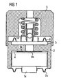
- Fig. 1 shows a thermal compensator with an adjustable stiffness, i.e. setting mechanism for the equilibrium position, based on a sliding sleeve.
- a compensator housing comprises an upper compensator housing part 3 and a lower compensator housing part 2, wherein the lower compensator housing part 2 contains a slidable piston 1a, which is able to slide axially inside the cylindrical lower compensator housing part 2.
- the upper compensator housing part 3 rests via its upper surface on the fix end stop of the injector, while the lower end rod of the piston 1a is in contact with the actuator assembly, e.g. the piezo-electric actuator.
- the lower end rod of the piston 1a is hermetically connected to a first metal membrane 7a that seals the bottom of the first fluid chamber 4 in which the piston 1a can axially slide.
- a second fluid chamber 5 is formed which is sealed by a second metal membrane 8 and a first guiding element 10 that holds a first end of a helical spring 6, i.e. provides a seat for the helical spring 6.
- the other end of the helical spring 6 rests against the inside of the upper compensator housing part 3 which is built as a sleeve overlapping the lower compensator housing part 2.
- the first and second fluid chambers 4, 5 are separated by a valve 9a which is formed by a spot welded metal plate having an orifice 9b to generate a high resistance for fluid passing from the first fluid chamber 4 to the second fluid chamber 5 and a low resistance for fluid passing from the second fluid chamber 5 to the first fluid chamber 4.
- the fluid with which both fluid chambers 4, 5 are fully filled and in which the piston 1a is therewith fully emerged might be silicone oil.
- the thermal compensator according to the first preferred exemplary embodiment of the present invention will be described.
- the top surface of the upper compensator housing part 3, i.e. the sleeve is in contact with the inlet fitting of the injector and the lower surface of the piston 1a is in contact with the actuator assembly, e.g. a piezo-electric actuator.
- the valve 9a which might be formed as a disk is welded by two (or more) spots at the portion of the lower compensator housing part 2 that separates the first and the second fluid chambers 4, 5 from each other and builds a fluid passage between them.
- the valve 9a presents a high hydraulic resistance during the actuation phase of the piezo-stack and allows a bigger oil passage due to the flapping effect of this metallic disk 9a during the following deactivation phase of the piezo-stack.
- this spring force can be set through the sliding movement between the upper compensator housing part 3 and the lower compensator housing part 2.
- these housing parts 2, 3 will be welded together and the spring preload or pre-compression will be "freezed".
- the upper compensator housing part 2 might alternatively be screwed onto the lower compensator housing part 3 and the spring force can be set by more or less screwing the housing parts together. Fixing the relative position of both housing parts might then perform the freezing of the spring preload.
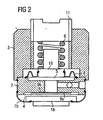
- Fig. 2 shows a thermal compensator according to the second exemplary embodiment of the present invention wherein the preload or pre-compression of the helical spring is adjustable with a screw that guides the second end of the helical spring 6, which screw 11 is fitted inside the upper compensator housing part 3.
- the thermal compensator according to the second exemplary embodiment is rather similar to that according to the first exemplary embodiment shown in Fig. 1, with the additional exception that not a slidable piston 1a is provided to be in contact with the actuator assembly, but a plate 1b which is welded to a metal membrane 7b with a saucer-like shape that is welded to the lower compensator housing part 2 to build the first fluid chamber 4.
- the function is identical to that of the first exemplary embodiment, i.e. the oil can only flow through the orifice 9b of the valve 9a, since the oil pressure itself that suddenly rises up, seals the passage through the side of the disk by a metal-to-metal sealing contact.
- the oil contained in the second fluid chamber 5 can quickly reflow into the first fluid chamber 4 through the gap generated between the lower surface of the lower compensator housing part 2 to which the valve is spot-welded and the disk of the valve 9b due to its flapping effect.
- the relative position of piston 1b and upper compensator housing part will be changed by thermal expansion.
- the hydraulic fluid will flow through the orifice 9a, the piston will get a new equilibrium position and the volumes of chambers 4 and 5 will be changed accordingly, so as the shape deformation of the metal membranes 7b, 8.
- the continuous position recovery of the plate 1b is guaranteed from the force of the spring 6 which is clamped between the first guide 10 and the screw 11 that forms a second guide.
- the spring 6 keeps the oil pressurised so that the oil flows back after each injection for restoring the pressure equilibrium between the fluid chambers, i.e.
- the spring force can be set by screwing the screw more or less into the upper compensator housing part 3.
- a sealing that can reach a zero leaking range is achieved together with an elimination of friction forces between the sliding parts and the possibility of calibrating the preload force during the assembly and calibration phase without changing the hydraulic and reservoir chamber height, that is without moving any component other than the adjusting screw and/or the sliding upper compensator housing part 3.
- a thermal compensator unit that allows to precisely set and keep an equilibrium position by providing an adjustable pre-compression on one of two fluid chambers.
- the fluid chambers respectively comprise at least one elastic element so that the respective volume is variable, which elastic elements hermetically seal the fluid chambers, which leads to the effect that no plastic or rubber dynamic sealing is necessary between the sliding parts in a hydraulic compensator, in particular since the moving parts of the hydraulic compensator are preferably hermetically connected to said respective elastic element and/or build a part thereof.
Landscapes
- Engineering & Computer Science (AREA)
- Chemical & Material Sciences (AREA)
- Combustion & Propulsion (AREA)
- Mechanical Engineering (AREA)
- General Engineering & Computer Science (AREA)
- Fuel-Injection Apparatus (AREA)
Description
- The present invention relates to a thermal compensator unit for use in a metering device for dosing pressurised fluid, in particular an injection valve for a fuel injection system in an internal combustion engine, said metering device comprising a housing with a metering opening, a valve needle passing through said housing, having a first end actuated by an actuator assembly outside said housing and a second end controlling the opening and closing of said metering opening, wherein said thermal compensator unit is arranged to cooperate with the actuator unit and the housing to compensate for different thermal expansion of the housing and the actuator assembly to ensure elastic contact between an end stop of the housing, the actuator assembly and the valve needle, said thermal compensator unit comprising transmission means for transmitting an axial extension of the actuator assembly to a compensator housing by urging a hydraulic fluid from a first fluid chamber to a second fluid chamber in an activation phase of said actuator assembly, wherein the first fluid chamber and the second fluid chamber are connected and comprise said hydraulic fluid in a predetermined distribution in an initial state in which the actuator assembly is not active, and a restoring means to return the hydraulic fluid to its initial state from the second fluid chamber to the first fluid chamber in a deactivation phase of the actuator assembly.
- Further, the present invention relates to a metering device, in particular an injection valve for a fuel injection system in an internal combustion engine, comprising a housing with a metering opening, a valve needle passing through said housing, having a first end actuated by an actuator assembly outside said housing and a second end controlling the opening and closing of said metering opening.
- In the construction of injector valves for gasoline high pressure direct injection through the actuation of an actuator assembly, in particular a piezo-electric group, it is essential that the requirements of fuel flow rate and the geometry of the jet are met under all possible operating conditions of the injector.
- Of particular importance is the influence of the temperature on the magnitude of the variations of the principle functional parameters of the injector. Within the required full range of the operating temperature from -40 °C to +150 °C, the flow rate and other parameters that characterise the operation of the injector must remain within predetermined limits of tolerance.
- As a result of the thermal expansions experienced by the outer steel housing of the injector, the piezo-electric actuator, having a lower coefficient of thermal expansion than the outer housing, would not maintain proper contact between its fixed end stop surface and the top end of the valve needle.
- To deal with this problem, i.e. to compensate the different thermal expansions of housing and piezo-electric stack, the injector valve is typically equipped with a hydraulic thermal compensation unit. As the operation temperature increases, the thermal compensation unit recovers the clearance that would otherwise be created between the valve needle and the piezo-electric actuator, thereby avoiding incorrect and potentially hazardous operation conditions.
- Fundamental requirements for such a thermal compensator unit are
- the ability to compensate the different thermal expansions guaranteeing the required capacities of injection to be obtained through the desired lift of the valve needle at the several predictable temperatures for the vehicle's activity,
- effectiveness during the usually fast thermal transitions,
- a total reliability of the device, and
- low manufacturing and assembly times and costs.
- US 2002/0179062 Al discloses a hydraulic compensator assembly for a piezoelectric fuel injector comprising a supply reservoir with bellows filled with a hydraulic fluid, a compression spring arranged outside the supply reservoir compressing the supply reservoir and an orifice that functions as a throttling passage that connects the supply reservoir with a fluid chamber of which the volume is defined by an axial position of a piston. An axial extension of a piezoelectric actuator is transmitted to the piston to urge the hydraulic fluid from the fluid chamber to the supply reservoir in an activation phase of the piezoelectric actuator. The compression spring returns the hydraulic fluid from the supply reservoir to the fluid chamber in a deactivation phase of the piezoelectric actuator, i.e. it resumes the equilibrium position. Plastic or rubber dynamic sealing elements, i.e. o-rings are used between the piston and the housing of the hydraulic compensator assembly to provide a sealing for the fluid chamber. However, these plastic or rubber dynamic sealing elements cannot be confidentially considered as sealing features that allow a zero-leakage performance. Also, these plastic or rubber dynamic sealing elements do apply friction forces between the sliding elements so that the sliding parts are not able to recover exactly the same equilibrium position without any residual misalignment due to friction forces at each temperature condition.
- In view of the foregoing it is an object underlying the present invention to provide a thermal compensator unit for use in a metering device of the above-mentioned type of which the equilibrium position is easily adjustable, as well as a metering device including such a thermal compensator unit.
- This object is achieved by a thermal compensator unit with the features of appended
claims 1 or 5. - Advantageous embodiments of the thermal compensator unit according to the present invention are disclosed in the respective following dependent claims.
- A metering device according to the present invention is defined in
claim 11. - According to a first preferred embodiment of the invention, the thermal compensator unit according to the preamble of claim 1 provides that a force to return the hydraulic fluid that is generated by said restoring means is adjustable during an assembly process in which said thermal compensator unit is assembled with said metering device. In other words, said restoring means provides a means to adjust its preload force instead of the requirement to change the design of the thermal compensator unit. Therewith, the equilibrium position is easily adjustable during the assembling of the thermal compensator unit in the metering device by adjusting the preload or pre-compression force. Said restoring means is arranged between an upper compensator housing part and a lower compensator housing part that are moveable against each other to adjust said pre-compression.
- According to a second preferred embodiment of the invention, the thermal compensator unit according to the preamble of
claim 5 provides that a force to return the hydraulic fluid that is generated by said restoring means is adjustable during an assembly process in which said thermal compensator unit is assembled with said metering device. In other words, said restoring means provides a means to adjust its preload force instead of the requirement to change the design of the thermal compensator unit. Therewith, the equilibrium position is easily adjustable during the assembling of the thermal compensator unit in the metering device by adjusting the preload or pre-compression force. Said restoring means is arranged between an upper compensator housing part and a lower compensator housing part that are fixed against each other and at least one of the upper compensator housing part and the lower compensator housing part comprises a moveable guiding element for said restoring means to adjust said pre-compression. - Further, according to the invention, the metering device according to the preamble of
claim 11 provides a thermal compensator unit according to the present invention. - Preferably, the thermal compensator unit according to the first preferred embodiment of the present invention further comprises a helical spring and/or a Belleville washer that gets pre-compressed during said assembly process and gets further compressed during the activation pace of said actuator assembly.
- Preferably, said upper compensator housing part and said lower compensator housing part might be slidable against each other to adjust said pre-compression and might get fixed against each other to set a predetermined pre-compression. As an alternative, said upper compensator housing part and said lower compensator housing part might be screwed together, wherein said pre-compression gets adjusted by more or less screwing both parts together.
- Preferably, said moveable guiding element might be a hollow screw in which one end of said restoring means is arranged.
- Preferably, the thermal compensator unit provides at least one respective elastic element for said first fluid chamber and said second fluid chamber so that a respective volume of the first fluid chamber and the second fluid chamber is variable within predetermined limits. Therewith, the first and second fluid chambers can be provided hermetically sealed with variable volumes without the need to use plastic or rubber dynamic sealing elements between the sliding parts. This leads to the ability to recover exactly the same equilibrium position at each temperature condition, since no residual misalignment due to friction forces between the sliding parts occurs. A side-effect is that a zero-leakage performance is allowed. In this case said elastic element is preferably a metal membrane.
- Alternatively or additionally preferably, said transmission means is connected to said elastic element of said first fluid chamber and/or builds a part thereof, and said restoring means is connected to said elastic element of said second fluid chamber and/or builds a part thereof. In any thermal compensator unit according to the present invention said first fluid chamber and said second fluid chamber might be separated by a valve that generates a high resistance for fluid passing from the first fluid chamber to the second fluid chamber and a low resistance for fluid passing from the second fluid chamber to the first fluid chamber.
- The invention, both its construction and its method of operation together with additional objects and advantages thereof, will best be understood from the following description of two specific exemplary embodiments when read in conjunction with the accompanying drawings, wherein
- Fig. 1
- is a schematic axially cross section of the thermal compensator unit according to a first exemplary embodiment of the present invention, and
- Fig. 2
- is a schematic axially cross section of the thermal compensator unit according to a second exemplary embodiment of the present invention.
- Fig. 1 shows a thermal compensator with an adjustable stiffness, i.e. setting mechanism for the equilibrium position, based on a sliding sleeve. As outlined in Fig. 1, a compensator housing comprises an upper
compensator housing part 3 and a lowercompensator housing part 2, wherein the lowercompensator housing part 2 contains aslidable piston 1a, which is able to slide axially inside the cylindrical lowercompensator housing part 2. The upper compensator housingpart 3 rests via its upper surface on the fix end stop of the injector, while the lower end rod of thepiston 1a is in contact with the actuator assembly, e.g. the piezo-electric actuator. The lower end rod of thepiston 1a is hermetically connected to afirst metal membrane 7a that seals the bottom of thefirst fluid chamber 4 in which thepiston 1a can axially slide. On the opposite side of the lowercompensator housing part 2, i.e. the other side with respect to the side on which thepiston 1a and thefirst metal membrane 7a are arranged, asecond fluid chamber 5 is formed which is sealed by a second metal membrane 8 and a first guidingelement 10 that holds a first end of ahelical spring 6, i.e. provides a seat for thehelical spring 6. - The other end of the
helical spring 6 rests against the inside of the uppercompensator housing part 3 which is built as a sleeve overlapping the lowercompensator housing part 2. The first andsecond fluid chambers valve 9a which is formed by a spot welded metal plate having anorifice 9b to generate a high resistance for fluid passing from thefirst fluid chamber 4 to thesecond fluid chamber 5 and a low resistance for fluid passing from thesecond fluid chamber 5 to thefirst fluid chamber 4. The fluid with which bothfluid chambers piston 1a is therewith fully emerged might be silicone oil. - In the following, the operation of the thermal compensator according to the first preferred exemplary embodiment of the present invention will be described. As mentioned, the top surface of the upper
compensator housing part 3, i.e. the sleeve, is in contact with the inlet fitting of the injector and the lower surface of thepiston 1a is in contact with the actuator assembly, e.g. a piezo-electric actuator. Thevalve 9a which might be formed as a disk is welded by two (or more) spots at the portion of the lowercompensator housing part 2 that separates the first and thesecond fluid chambers valve 9a presents a high hydraulic resistance during the actuation phase of the piezo-stack and allows a bigger oil passage due to the flapping effect of thismetallic disk 9a during the following deactivation phase of the piezo-stack. - This effect is given, since during the actuation phase of the piezo-stack, the
piston 1a is pushed upwardly from the piezo-electric group, which action forces the silicone oil contained in thefirst fluid chamber 4 to pass through theorifice 9b in thedisk 9a into thesecond fluid chamber 5. On the other hand, during the deactivation phase of the piezo-stack, the oil contained in thesecond fluid chamber 5 can quickly reflow into thefirst fluid chamber 4 through the gap generated between the surface on which thevalve 9a is spot-welded and thevalve 9a due to the flapping effect of the disk that forms thevalve 9a at portions in which it is not spot-welded to said surface. - The relative position of
piston 1a and upper compensator housing part will be changed by thermal expansion. In such relatively slow motion, the hydraulic fluid will flow through theorifice 9a, the piston will get a new equilibrium position and the volumes ofchambers metal membranes 7a, 8. - At each injection, the continuous position recovery of the
piston 1a is guaranteed from the force of thespring 6 that pressurises thesecond fluid chamber 5, since it is clamped between the first guidingelement 10 and the uppercompensator housing part 3. - During the assembly process, this spring force can be set through the sliding movement between the upper
compensator housing part 3 and the lowercompensator housing part 2. After the calibration, thesehousing parts compensator housing part 2 might alternatively be screwed onto the lowercompensator housing part 3 and the spring force can be set by more or less screwing the housing parts together. Fixing the relative position of both housing parts might then perform the freezing of the spring preload. - Fig. 2 shows a thermal compensator according to the second exemplary embodiment of the present invention wherein the preload or pre-compression of the helical spring is adjustable with a screw that guides the second end of the
helical spring 6, which screw 11 is fitted inside the uppercompensator housing part 3. Apart from thisscrew 11 the thermal compensator according to the second exemplary embodiment is rather similar to that according to the first exemplary embodiment shown in Fig. 1, with the additional exception that not aslidable piston 1a is provided to be in contact with the actuator assembly, but aplate 1b which is welded to ametal membrane 7b with a saucer-like shape that is welded to the lowercompensator housing part 2 to build the firstfluid chamber 4. - The function is identical to that of the first exemplary embodiment, i.e. the oil can only flow through the
orifice 9b of thevalve 9a, since the oil pressure itself that suddenly rises up, seals the passage through the side of the disk by a metal-to-metal sealing contact. During the deactivation phase of the piezo-stack, the oil contained in the secondfluid chamber 5 can quickly reflow into the firstfluid chamber 4 through the gap generated between the lower surface of the lowercompensator housing part 2 to which the valve is spot-welded and the disk of thevalve 9b due to its flapping effect. The relative position ofpiston 1b and upper compensator housing part will be changed by thermal expansion. In such relatively slow motion, the hydraulic fluid will flow through theorifice 9a, the piston will get a new equilibrium position and the volumes ofchambers metal membranes 7b, 8. In this embodiment, the continuous position recovery of theplate 1b is guaranteed from the force of thespring 6 which is clamped between thefirst guide 10 and thescrew 11 that forms a second guide. Thespring 6 keeps the oil pressurised so that the oil flows back after each injection for restoring the pressure equilibrium between the fluid chambers, i.e. so that the equilibrium position that is defined by the pre-compression of the spring which might be adjusted with thescrew 11 and which is constant for all temperature ranges due to the usage of elastic elements, such as the shown metal membranes, to have variable volumes of the first andsecond fluid chambers compensator housing part 3. - According to the present invention a sealing that can reach a zero leaking range is achieved together with an elimination of friction forces between the sliding parts and the possibility of calibrating the preload force during the assembly and calibration phase without changing the hydraulic and reservoir chamber height, that is without moving any component other than the adjusting screw and/or the sliding upper
compensator housing part 3. - Therewith, a thermal compensator unit is disclosed that allows to precisely set and keep an equilibrium position by providing an adjustable pre-compression on one of two fluid chambers. Further, the fluid chambers respectively comprise at least one elastic element so that the respective volume is variable, which elastic elements hermetically seal the fluid chambers, which leads to the effect that no plastic or rubber dynamic sealing is necessary between the sliding parts in a hydraulic compensator, in particular since the moving parts of the hydraulic compensator are preferably hermetically connected to said respective elastic element and/or build a part thereof.
Claims (11)
- A thermal compensator unit for use in a metering device for dosing pressurised fluid, in particular an injection valve for a fuel injection system in an internal combustion engine, said metering device comprisingwherein said thermal compensator unit is suitable to be arranged to cooperate with the actuator unit and the housing to compensate for different thermal expansion of the housing and the actuator assembly to ensure elastic contact between an end stop of the housing, the actuator assembly and the valve needle, said thermal compensator unit comprisinga housing with a metering opening,a valve needle passing through said housing, having a first end actuated by an actuator assembly outside said housing and a second end controlling the opening and closing of said metering opening,characterised in thattransmission means (1a, 1b) for transmitting an axial extension of the actuator assembly to a compensator housing (2, 3) by urging a hydraulic fluid from a first fluid chamber (4) to a second fluid chamber (5) in an activation phase of said actuator assembly, wherein the first fluid chamber (4) and the second fluid chamber (5) are connected and comprise said hydraulic fluid in a predetermined distribution in an initial state in which the actuator assembly is not active, anda restoring means (6) to return the hydraulic fluid to its initial state from the second fluid chamber (5) to the first fluid chamber (4) in a deactivation phase of the actuator assembly and a force to return the hydraulic fluid that is generated by said restoring means (6) is adjustable during an assembly process in which said thermal compensator unit is assembled with said metering device,
said restoring means (6) is arranged between an upper compensator housing part (3) and a lower compensator housing part (2) that are moveable against each other to adjust said pre-compression. - The thermal compensator unit according to claim 1,
characterised in that
said restoring means comprises a helical spring (6) and/or a Belleville washer that gets pre-compressed during said assembly process and gets further compressed during the activation phase of said actuator assembly. - The thermal compensator unit according to claim 2,
characterised in that
said upper compensator housing part (3) and said lower compensator housing part (2) are slidable against each other to adjust said pre-compression and are fixed against each other to set a predetermined pre-compression. - The thermal compensator unit according to claim 2,
characterised in that
said upper compensator housing part and said lower compensator housing part are screwed together, wherein said pre-compression gets adjusted by more or less screwing both parts together. - A thermal compensator unit for use in a metering device for dosing pressurised fluid, in particular an injection valve for a fuel injection system in an internal combustion engine, said metering device comprisingwherein said thermal compensator unit is suitable to be arranged to cooperate with the actuator unit and the housing to compensate for different thermal expansion of the housing and the actuator assembly to ensure elastic contact between an end stop of the housing, the actuator assembly and the valve needle, said thermal compensator unit comprisinga housing with a metering opening,a valve needle passing through said housing, having a first end actuated by an actuator assembly outside said housing and a second end controlling the opening and closing of said metering opening,characterised in thattransmission means (1a, 1b) for transmitting an axial extension of the actuator assembly to a compensator housing (2, 3) by urging a hydraulic fluid from a first fluid chamber (4) to a second fluid chamber (5) in an activation phase of said actuator assembly, wherein the first fluid chamber (4) and the second fluid chamber (5) are connected and comprise said hydraulic fluid in a predetermined distribution in an initial state in which the actuator assembly is not active, anda restoring means (6) to return the hydraulic fluid to its initial state from the second fluid chamber (5) to the first fluid chamber (4) in a deactivation phase of the actuator assembly and a force to return the hydraulic fluid that is generated by said restoring means (6) is adjustable during an assembly process in which said thermal compensator unit is assembled with said metering device,
said restoring means (6) is arranged between an upper compensator housing part (3) and a lower compensator housing part (2) that are fixed against each other and at least one of the upper compensator housing part (2) and the lower compensator housing part comprises a moveable guiding element (11) for said restoring means to adjust said pre-compression. - The thermal compensator unit according to claim 5,
characterised in that
said moveable guiding element (11) is a hollow screw in which one end of said restoring means is arranged. - The thermal compensator unit according to anyone of the preceding claims,
characterised in that
said first fluid chamber (4) and said second fluid chamber (5) respectively comprise at least one elastic element (7a, 7b, 8) so that a respective volume of the first fluid chamber (4) and the second fluid chamber (5) is variable within predetermined limits. - The thermal compensator unit according to claim 7,
characterised in that
said elastic element (7a, 7b, 8) is a metal membrane. - The thermal compensator unit according to claim 7 or 8,
characterised in that
said transmission means (1a, 1b) is connected to said elastic element (7a, 7b) of said first fluid chamber (4) and/or builds a part thereof, and said restoring means (6) is connected to said elastic element (8) of said second fluid chamber (5) and/or builds a part thereof. - The thermal compensator unit according to anyone of the preceding claims,
characterised in that
said first fluid chamber (4) and said second fluid chamber (5) are separated by a valve (9a, 9b) that generates a high resistance for fluid passing from the first fluid chamber (4) to the second fluid chamber (5) and a low resistance for fluid passing from the second fluid chamber (5) to the first fluid chamber (4). - A metering device, in particular an injection valve for a fuel injection system in an internal combustion engine, comprisingcharacterised bya housing with a metering opening,a valve needle passing through said housing, having a first end actuated by an actuator assembly outside said housing and a second end controlling the opening and closing of said metering opening,
a thermal compensator unit according to anyone of claims 1 to 10.
Priority Applications (4)
| Application Number | Priority Date | Filing Date | Title |
|---|---|---|---|
| DE60302329T DE60302329T2 (en) | 2003-02-04 | 2003-02-04 | Compensator to compensate for thermal expansion for a metering device |
| EP03002397A EP1445479B1 (en) | 2003-02-04 | 2003-02-04 | Thermal compensator unit for use in a metering device |
| EP04015516A EP1464828B1 (en) | 2003-02-04 | 2003-02-04 | Thermal compensator unit for use in a metering device |
| DE60306106T DE60306106T2 (en) | 2003-02-04 | 2003-02-04 | Compensator to compensate for thermal expansion for a metering device |
Applications Claiming Priority (1)
| Application Number | Priority Date | Filing Date | Title |
|---|---|---|---|
| EP03002397A EP1445479B1 (en) | 2003-02-04 | 2003-02-04 | Thermal compensator unit for use in a metering device |
Related Child Applications (1)
| Application Number | Title | Priority Date | Filing Date |
|---|---|---|---|
| EP04015516A Division EP1464828B1 (en) | 2003-02-04 | 2003-02-04 | Thermal compensator unit for use in a metering device |
Publications (2)
| Publication Number | Publication Date |
|---|---|
| EP1445479A1 EP1445479A1 (en) | 2004-08-11 |
| EP1445479B1 true EP1445479B1 (en) | 2005-11-16 |
Family
ID=32605310
Family Applications (2)
| Application Number | Title | Priority Date | Filing Date |
|---|---|---|---|
| EP04015516A Expired - Lifetime EP1464828B1 (en) | 2003-02-04 | 2003-02-04 | Thermal compensator unit for use in a metering device |
| EP03002397A Expired - Lifetime EP1445479B1 (en) | 2003-02-04 | 2003-02-04 | Thermal compensator unit for use in a metering device |
Family Applications Before (1)
| Application Number | Title | Priority Date | Filing Date |
|---|---|---|---|
| EP04015516A Expired - Lifetime EP1464828B1 (en) | 2003-02-04 | 2003-02-04 | Thermal compensator unit for use in a metering device |
Country Status (2)
| Country | Link |
|---|---|
| EP (2) | EP1464828B1 (en) |
| DE (2) | DE60302329T2 (en) |
Families Citing this family (3)
| Publication number | Priority date | Publication date | Assignee | Title |
|---|---|---|---|---|
| EP1813805A1 (en) * | 2006-01-27 | 2007-08-01 | Siemens VDO Automotive S.p.A. | Compensation assembly for an injector |
| DE102006013958B4 (en) * | 2006-03-27 | 2016-11-10 | Robert Bosch Gmbh | Fuel injector |
| DE102007053426A1 (en) * | 2007-11-09 | 2009-05-14 | Robert Bosch Gmbh | Piezoelectric actuator module |
Family Cites Families (4)
| Publication number | Priority date | Publication date | Assignee | Title |
|---|---|---|---|---|
| US6260541B1 (en) * | 2000-04-26 | 2001-07-17 | Delphi Technologies, Inc. | Hydraulic lash adjuster |
| DE10030232A1 (en) * | 2000-06-20 | 2002-01-17 | Siemens Ag | Device for transmitting a movement with play compensation |
| DE10046323B4 (en) * | 2000-09-19 | 2004-02-12 | Siemens Ag | Hydraulic backlash compensation system |
| US6499471B2 (en) * | 2001-06-01 | 2002-12-31 | Siemens Automotive Corporation | Hydraulic compensator for a piezoelectrical fuel injector |
-
2003
- 2003-02-04 EP EP04015516A patent/EP1464828B1/en not_active Expired - Lifetime
- 2003-02-04 DE DE60302329T patent/DE60302329T2/en not_active Expired - Fee Related
- 2003-02-04 EP EP03002397A patent/EP1445479B1/en not_active Expired - Lifetime
- 2003-02-04 DE DE60306106T patent/DE60306106T2/en not_active Expired - Fee Related
Also Published As
| Publication number | Publication date |
|---|---|
| DE60306106T2 (en) | 2006-11-16 |
| DE60302329D1 (en) | 2005-12-22 |
| EP1464828A1 (en) | 2004-10-06 |
| EP1464828B1 (en) | 2006-06-14 |
| EP1445479A1 (en) | 2004-08-11 |
| DE60302329T2 (en) | 2006-06-22 |
| DE60306106D1 (en) | 2006-07-27 |
Similar Documents
| Publication | Publication Date | Title |
|---|---|---|
| US7886993B2 (en) | Injection valve | |
| JP4052383B2 (en) | Pressure response valve for compensator of solid state actuator | |
| US6148842A (en) | Compensation element for the compensation of temperature-conditioned length changes of an object | |
| US5630550A (en) | Fuel injection system | |
| US6749126B1 (en) | Fuel injector and method for its operation | |
| US6155532A (en) | Valve for controlling fluids | |
| CN100567729C (en) | fuel injection valve | |
| US6464202B1 (en) | Valve for controlling liquids | |
| CN103201498B (en) | Fuel injector | |
| CN1327507A (en) | Fuel injection valve | |
| EP1389276B1 (en) | Directly actuated injection valve with a composite needle | |
| KR20010101058A (en) | Valve for controlling liquids | |
| KR100881583B1 (en) | Fuel injection valve | |
| KR101450367B1 (en) | Piezoelectric valve | |
| CZ20011881A3 (en) | Valve for controlling liquids | |
| US7077377B2 (en) | Device for the translation of a displacement of an actuator, in particular for an injection valve | |
| US6260541B1 (en) | Hydraulic lash adjuster | |
| KR100942670B1 (en) | Fuel injection valve | |
| EP1464828B1 (en) | Thermal compensator unit for use in a metering device | |
| KR20010101483A (en) | Fuel injection valve | |
| US20080053410A1 (en) | Fuel injector with pressure balancing valve | |
| CN1196855C (en) | Fuel injection valve | |
| EP1391608B1 (en) | Metering device with thermal compensator unit | |
| EP1813805A1 (en) | Compensation assembly for an injector | |
| JP3852145B2 (en) | Fuel injection valve |
Legal Events
| Date | Code | Title | Description |
|---|---|---|---|
| PUAI | Public reference made under article 153(3) epc to a published international application that has entered the european phase |
Free format text: ORIGINAL CODE: 0009012 |
|
| AK | Designated contracting states |
Kind code of ref document: A1 Designated state(s): AT BE BG CH CY CZ DE DK EE ES FI FR GB GR HU IE IT LI LU MC NL PT SE SI SK TR |
|
| AX | Request for extension of the european patent |
Extension state: AL LT LV MK RO |
|
| 17P | Request for examination filed |
Effective date: 20050207 |
|
| GRAP | Despatch of communication of intention to grant a patent |
Free format text: ORIGINAL CODE: EPIDOSNIGR1 |
|
| AKX | Designation fees paid |
Designated state(s): DE FR GB IT |
|
| GRAS | Grant fee paid |
Free format text: ORIGINAL CODE: EPIDOSNIGR3 |
|
| GRAA | (expected) grant |
Free format text: ORIGINAL CODE: 0009210 |
|
| AK | Designated contracting states |
Kind code of ref document: B1 Designated state(s): DE FR GB IT |
|
| REG | Reference to a national code |
Ref country code: GB Ref legal event code: FG4D |
|
| REF | Corresponds to: |
Ref document number: 60302329 Country of ref document: DE Date of ref document: 20051222 Kind code of ref document: P |
|
| ET | Fr: translation filed | ||
| PLBE | No opposition filed within time limit |
Free format text: ORIGINAL CODE: 0009261 |
|
| STAA | Information on the status of an ep patent application or granted ep patent |
Free format text: STATUS: NO OPPOSITION FILED WITHIN TIME LIMIT |
|
| 26N | No opposition filed |
Effective date: 20060817 |
|
| PGFP | Annual fee paid to national office [announced via postgrant information from national office to epo] |
Ref country code: DE Payment date: 20090219 Year of fee payment: 7 |
|
| PGFP | Annual fee paid to national office [announced via postgrant information from national office to epo] |
Ref country code: GB Payment date: 20090219 Year of fee payment: 7 |
|
| PGFP | Annual fee paid to national office [announced via postgrant information from national office to epo] |
Ref country code: IT Payment date: 20090220 Year of fee payment: 7 |
|
| PGFP | Annual fee paid to national office [announced via postgrant information from national office to epo] |
Ref country code: FR Payment date: 20090213 Year of fee payment: 7 |
|
| GBPC | Gb: european patent ceased through non-payment of renewal fee |
Effective date: 20100204 |
|
| REG | Reference to a national code |
Ref country code: FR Ref legal event code: ST Effective date: 20101029 |
|
| PG25 | Lapsed in a contracting state [announced via postgrant information from national office to epo] |
Ref country code: FR Free format text: LAPSE BECAUSE OF NON-PAYMENT OF DUE FEES Effective date: 20100301 |
|
| PG25 | Lapsed in a contracting state [announced via postgrant information from national office to epo] |
Ref country code: DE Free format text: LAPSE BECAUSE OF NON-PAYMENT OF DUE FEES Effective date: 20100901 |
|
| PG25 | Lapsed in a contracting state [announced via postgrant information from national office to epo] |
Ref country code: IT Free format text: LAPSE BECAUSE OF NON-PAYMENT OF DUE FEES Effective date: 20100204 Ref country code: GB Free format text: LAPSE BECAUSE OF NON-PAYMENT OF DUE FEES Effective date: 20100204 |