EP1445208A1 - Liquid container having cap with slit valve - Google Patents
Liquid container having cap with slit valve Download PDFInfo
- Publication number
- EP1445208A1 EP1445208A1 EP02733244A EP02733244A EP1445208A1 EP 1445208 A1 EP1445208 A1 EP 1445208A1 EP 02733244 A EP02733244 A EP 02733244A EP 02733244 A EP02733244 A EP 02733244A EP 1445208 A1 EP1445208 A1 EP 1445208A1
- Authority
- EP
- European Patent Office
- Prior art keywords
- container
- slit
- cap
- valve
- liquid
- Prior art date
- Legal status (The legal status is an assumption and is not a legal conclusion. Google has not performed a legal analysis and makes no representation as to the accuracy of the status listed.)
- Withdrawn
Links
- 239000007788 liquid Substances 0.000 title claims abstract description 27
- 238000011109 contamination Methods 0.000 description 5
- 230000008023 solidification Effects 0.000 description 4
- 238000007711 solidification Methods 0.000 description 4
- 239000002537 cosmetic Substances 0.000 description 2
- 210000000707 wrist Anatomy 0.000 description 2
- 229920000297 Rayon Polymers 0.000 description 1
- 230000002411 adverse Effects 0.000 description 1
- 239000003599 detergent Substances 0.000 description 1
- 238000007599 discharging Methods 0.000 description 1
- 210000000245 forearm Anatomy 0.000 description 1
- 230000004927 fusion Effects 0.000 description 1
- 239000003921 oil Substances 0.000 description 1
- 235000019198 oils Nutrition 0.000 description 1
- 239000000126 substance Substances 0.000 description 1
- 235000015112 vegetable and seed oil Nutrition 0.000 description 1
- 239000008158 vegetable oil Substances 0.000 description 1
Images


Classifications
-
- B—PERFORMING OPERATIONS; TRANSPORTING
- B65—CONVEYING; PACKING; STORING; HANDLING THIN OR FILAMENTARY MATERIAL
- B65D—CONTAINERS FOR STORAGE OR TRANSPORT OF ARTICLES OR MATERIALS, e.g. BAGS, BARRELS, BOTTLES, BOXES, CANS, CARTONS, CRATES, DRUMS, JARS, TANKS, HOPPERS, FORWARDING CONTAINERS; ACCESSORIES, CLOSURES, OR FITTINGS THEREFOR; PACKAGING ELEMENTS; PACKAGES
- B65D35/00—Pliable tubular containers adapted to be permanently or temporarily deformed to expel contents, e.g. collapsible tubes for toothpaste or other plastic or semi-liquid material; Holders therefor
- B65D35/44—Closures
- B65D35/46—Closures with valves
-
- B—PERFORMING OPERATIONS; TRANSPORTING
- B65—CONVEYING; PACKING; STORING; HANDLING THIN OR FILAMENTARY MATERIAL
- B65D—CONTAINERS FOR STORAGE OR TRANSPORT OF ARTICLES OR MATERIALS, e.g. BAGS, BARRELS, BOTTLES, BOXES, CANS, CARTONS, CRATES, DRUMS, JARS, TANKS, HOPPERS, FORWARDING CONTAINERS; ACCESSORIES, CLOSURES, OR FITTINGS THEREFOR; PACKAGING ELEMENTS; PACKAGES
- B65D47/00—Closures with filling and discharging, or with discharging, devices
- B65D47/04—Closures with discharging devices other than pumps
- B65D47/20—Closures with discharging devices other than pumps comprising hand-operated members for controlling discharge
- B65D47/2018—Closures with discharging devices other than pumps comprising hand-operated members for controlling discharge comprising a valve or like element which is opened or closed by deformation of the container or closure
- B65D47/2031—Closures with discharging devices other than pumps comprising hand-operated members for controlling discharge comprising a valve or like element which is opened or closed by deformation of the container or closure the element being formed by a slit, narrow opening or constrictable spout, the size of the outlet passage being able to be varied by increasing or decreasing the pressure
Definitions
- the present invention relates to a liquid container comprising a cap with a slit valve, and contemplates to improve shut-off performance upon discharge of various kinds of contents and effectively avoid malfunctioning of the valve or contamination of the cap due to attachment or solidification of the contents around the discharge opening.
- a liquid container for cosmetics or detergent which is provided with a slit valve for allowing discharge of a desired amount of contents and good shut-off performance upon discharge of the contents.
- a liquid container is disclosed, e.g., in U.S. Patent No. 5,897,033, the disclosure of which is herein incorporated by reference.
- a slit valve has slits that are arranged in the form of a cross, so as to discharge a desired amount of contents by grasping and pressurizing the container body to increase the inner pressure, and thereby instantaneously open the slit portion that is situated at the center region of the valve.
- the present invention provides liquid container comprising a container body that can be resiliently deformed when grasped and pressed by user, and a cap secured to a mouth portion of the container body.
- the cap comprises a cap body having an opening in communication with interior of the container, and a slit valve having slits that can be opened to discharge a desired amount of a liquid within the container, with the container tilted and the container body pressed.
- the slits comprise a first slit that extends in a direction in which the container is to be tilted, and a second slit intersecting with the first slit.
- the slits of the slit valve provided for the cap comprise a first slit that extends in a direction in which the container is to be tilted, and a second slit intersecting with the first slit, it is possible to achieve improved shut-off performance upon discharge of the contents irrespectively of its viscosity, and thereby effectively avoid malfunctioning of the valve or contamination at the periphery of the discharge opening due to attachment or solidification of the contents.
- container body has a cross-sectional shape that determines the direction in which said container is to be tilted as it is grasped by user.
- the container body has a flat cross-sectional shape, and it is particularly preferred that one of said first slit and said second slit of the slit valve extends in a direction of major axis of the container as seen in its cross-section, and the other of said first slit and said second slit extends in a direction of minor axis of the container.
- the cap further comprises a cover that is hinge-connected to the cap main body so as to be movable between a closed position where it is engaged by the cap main body and an open position exposing said slit valve.
- the liquid container according to the present invention further comprises a valve retainer that cooperates with the cap main body to hold the slit valve, and positioning means for determining an angular position of the valve retainer relative to the cap main body.
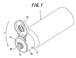
- FIG. 1 is a perspective view showing the appearance of the liquid container according to one embodiment of the present invention.
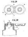
- FIGS. 2A and 2B are plan view and sectional view, respectively, of the cap shown in FIG. 1.
- FIG. 3 is a view explaining the manner of incorporating a valve into the cap main body.
- FIG. 4 is a view explaining a state in which the content is attached to the tip end portion of the valve.
- FIGS. 5Aand 5B are bottom view and sectional view, respectively, of the valve positioning means.
- FIG. 6 is a view useful for analyzing the tilting behavior of user's hand grasping an object.
- FIG. 7 is a perspective view showing the appearance of the liquid container according to another embodiment of the present invention.
- FIG. 1 a liquid container according to one embodiment of the present invention, which comprises a cap with a slit valve.
- Reference numeral 1 designates a generally cylindrical container body, and 2 a cap that is secured to a mouth portion of the container body 1.
- the cap 2 has an opening O that is in communication with the interior of the container body 1, and is comprised of a cap body 2a threadedly connected to the mouth portion of the container body 1, a slit valve 2b arranged at the opening O of the cap body 2a, and clamped between the cap body 2a and a valve retainer 3 and thereby fixedly held in place, as well as a cover 2c for covering the slit valve 2b and detachably hold by the can body 2a, wherein the cover 2c may be of a hinge-connection type.
- the slit valve 2b has a tip end portion that is formed with cross-like slits comprised of a first slit S 1 extending along a direction T in which the container is to be tilted, and a second slit S 2 intersecting at right angles with the first silt S 1 .
- the tilting movement of the hand is classified into a twisting movement about a longitudinal axis x-x of the forearm, a twisting movement about an axis y-y that passes the wrist and is substantially perpendicular to the general surface of the palm, and a twisting movement about an axis z-z of the wrist, which is substantially parallel to the general surface of the palm, wherein the tree axes x-x, y-y , z-z are perpendicular to each other.
- valve In conventional cap provided with a slit valve, an exact control is not performed for positioning the valve relative to the cap body and, hence, to the container body.
- the valve is mounted without taking into consideration the direction in which the liquid container is tilted.
- the shut-off performance may not be satisfactory depending upon properties of the contents, giving rise to a situation wherein the contents remain attached to the tip end portion of the valve, and resulting in obstacle to opening operation of the valve, or contamination at the periphery of the discharge opening.
- the slit S1 of the slit valve extends in the direction T in which the container is to be tilted.
- the valve retainer 3 is provided with projections 3a, while the cap body 2a for supporting the valve retainer 3 is provided with recesses "h" corresponding to the projections 3a.
- the slit valve 2a and the valve retainer 3 are previously positioned relative to each other so that, when the projections 3a of the valve retainer 3 are engaged with the recesses "h", the slit S1 is aligned in the direction in which the container is tilted.
- the positioning structure is illustrated in FIGS.
- valve retainer 3 and the valve body 2a are fittingly engaged with each other.
- the present invention is not limited to such a structure, and other fitting form may be applied, besides that fusion bonding means or adhesion means may be adopted, as may be appropriately selected.
- FIG. 7 shows another embodiment wherein the present invention is applied to a container of tube-type, wherein the container body has a flat sectional shape.
- the cap 2 secured to such container has a cover 2c that can be detached from the cap body 2a.
- the cap is secured so that the slit S 1 of the slit valve extends in the tilting direction T of the container, assuming that the contents are discharged by tilting the container with its wide sides directed upwards and downwards.
- the slit S 1 of the slit valve extends in the tilting direction T of the container, it is possible to achieve an improved shut-off performance of the liquid.
- the slits S2 extends in the tilting direction T so as to improve the shut-off-performance of the liquid.
- the direction T in which the container is tilted may be determined by appropriately designing the securing position of the hinge-type cover or the shape of the container body. Besides, it is also possible to indicate the direction in which the container is to be tilted for discharging the contents, by applying an arrow or the like marking (not shown) to the cap or the container body.
Landscapes
- Engineering & Computer Science (AREA)
- Mechanical Engineering (AREA)
- Closures For Containers (AREA)
Abstract
A liquid container according to the present invention includes a
container body (1) that can be resiliently deformed when grasped and pressed by
user, and a cap (2) secured to a mouth portion of the container body (1). The cap
(2) includes a cap body (2a) having an opening (O) in communication with interior
of the container, and a slit valve (2b) having slits that can be opened to discharge a
desired amount of a liquid within the container, with the container tilted and the
container body (1) pressed. Further, the slits include a first slit (S1) that extends in a
direction (T) in which the container is to be tilted, and a second slit (S2) intersecting
with the first slit (S1).
Description
The present invention relates to a liquid container comprising a cap with
a slit valve, and contemplates to improve shut-off performance upon discharge of
various kinds of contents and effectively avoid malfunctioning of the valve or
contamination of the cap due to attachment or solidification of the contents around
the discharge opening.
A liquid container for cosmetics or detergent is known, which is
provided with a slit valve for allowing discharge of a desired amount of contents and
good shut-off performance upon discharge of the contents. Such a liquid container
is disclosed, e.g., in U.S. Patent No. 5,897,033, the disclosure of which is herein
incorporated by reference. Typically, a slit valve has slits that are arranged in the
form of a cross, so as to discharge a desired amount of contents by grasping and
pressurizing the container body to increase the inner pressure, and thereby
instantaneously open the slit portion that is situated at the center region of the valve.
Conventional slit valve operates satisfactorily, when the contents is a
highly viscose liquid, such as creamy substance. However, when the contents is a
liquid with low viscosity, such as oil-based cosmetics or vegetable oil, due to
insufficient shut-off performance upon discharge of the contents, it is inevitable that
the contents remains attached to the tip end portion of the valve. When the attached
contents is left as it is, the contents undergoes solidification and often adversely
affects the opening motion of the valve or causes contamination at the periphery of
the discharge opening.
It is therefore a primary object of the present invention to provide a
novel liquid container comprising a cap with a slit valve that exhibits a satisfactory
shut-off performance of the contents upon discharge.
To this end, the present invention provides liquid container comprising a
container body that can be resiliently deformed when grasped and pressed by user,
and a cap secured to a mouth portion of the container body. The cap comprises a
cap body having an opening in communication with interior of the container, and a
slit valve having slits that can be opened to discharge a desired amount of a liquid
within the container, with the container tilted and the container body pressed.
Further, the slits comprise a first slit that extends in a direction in which the container
is to be tilted, and a second slit intersecting with the first slit.
Since, according to the present invention, the slits of the slit valve
provided for the cap comprise a first slit that extends in a direction in which the
container is to be tilted, and a second slit intersecting with the first slit, it is possible
to achieve improved shut-off performance upon discharge of the contents
irrespectively of its viscosity, and thereby effectively avoid malfunctioning of the
valve or contamination at the periphery of the discharge opening due to attachment
or solidification of the contents.
It is preferred that container body has a cross-sectional shape that
determines the direction in which said container is to be tilted as it is grasped by user.
In this instance, it is preferred that the container body has a flat cross-sectional shape,
and it is particularly preferred that one of said first slit and said second slit of the slit
valve extends in a direction of major axis of the container as seen in its cross-section,
and the other of said first slit and said second slit extends in a direction of minor axis
of the container.
It is preferred that the cap further comprises a cover that is
hinge-connected to the cap main body so as to be movable between a closed position
where it is engaged by the cap main body and an open position exposing said slit
valve.
Moreover, it is preferred that the liquid container according to the
present invention further comprises a valve retainer that cooperates with the cap
main body to hold the slit valve, and positioning means for determining an angular
position of the valve retainer relative to the cap main body.
The present invention will be described below in further detail, with
reference to preferred embodiments shown in the accompanying drawings.
FIG. 1 is a perspective view showing the appearance of the liquid
container according to one embodiment of the present invention.
FIGS. 2A and 2B are plan view and sectional view, respectively, of the
cap shown in FIG. 1.
FIG. 3 is a view explaining the manner of incorporating a valve into the
cap main body.
FIG. 4 is a view explaining a state in which the content is attached to the
tip end portion of the valve.
FIGS. 5Aand 5B are bottom view and sectional view, respectively, of the
valve positioning means.
FIG. 6 is a view useful for analyzing the tilting behavior of user's hand
grasping an object.
FIG. 7 is a perspective view showing the appearance of the liquid
container according to another embodiment of the present invention.
There is shown, in FIG. 1, a liquid container according to one
embodiment of the present invention, which comprises a cap with a slit valve.
Reference numeral 1 designates a generally cylindrical container body, and 2 a cap
that is secured to a mouth portion of the container body 1.
As shown in the plan view and sectional view of FIGS. 2A and 2B, the
cap 2 has an opening O that is in communication with the interior of the container
body 1, and is comprised of a cap body 2a threadedly connected to the mouth portion
of the container body 1, a slit valve 2b arranged at the opening O of the cap body 2a,
and clamped between the cap body 2a and a valve retainer 3 and thereby fixedly held
in place, as well as a cover 2c for covering the slit valve 2b and detachably hold by
the can body 2a, wherein the cover 2c may be of a hinge-connection type.
The slit valve 2b has a tip end portion that is formed with cross-like slits
comprised of a first slit S1 extending along a direction T in which the container is to
be tilted, and a second slit S2 intersecting at right angles with the first silt S1.
With reference to FIG. 6, analysis is made of tilting movement of user's
hand when grasping an object such as a liquid container. In many instance, the
tilting movement of the hand is classified into a twisting movement about a
longitudinal axis x-x of the forearm, a twisting movement about an axis y-y that
passes the wrist and is substantially perpendicular to the general surface of the palm,
and a twisting movement about an axis z-z of the wrist, which is substantially
parallel to the general surface of the palm, wherein the tree axes x-x, y-y, z-z are
perpendicular to each other.
In conventional cap provided with a slit valve, an exact control is not
performed for positioning the valve relative to the cap body and, hence, to the
container body. Thus, as shown in FIG. 3, the valve is mounted without taking into
consideration the direction in which the liquid container is tilted. In this instance,
when the liquid container is tilted to discharge the contents, the shut-off performance
may not be satisfactory depending upon properties of the contents, giving rise to a
situation wherein the contents remain attached to the tip end portion of the valve, and
resulting in obstacle to opening operation of the valve, or contamination at the
periphery of the discharge opening.
In the cap according to the present invention, the slit S1 of the slit valve
extends in the direction T in which the container is to be tilted. Thus, when
pressure is released from the container body and a vacuum pressure is thereby
produced in the container so that the valve is operated from the open position to the
closing position, the contents at the tip end portion of the valve is sucked back into
the container body to realize a satisfactory shut-off performance even in the case of
contents having a low viscosity.
In order to perform positioning of the slits S1, S2 when the slit valve 2b is
mounted into the cap body 2a, as shown in FIGS, 5A and 5B, the valve retainer 3 is
provided with projections 3a, while the cap body 2a for supporting the valve retainer
3 is provided with recesses "h" corresponding to the projections 3a. The slit valve
2a and the valve retainer 3 are previously positioned relative to each other so that,
when the projections 3a of the valve retainer 3 are engaged with the recesses "h", the
slit S1 is aligned in the direction in which the container is tilted. The positioning
structure is illustrated in FIGS. 5A and 5B with reference to an example wherein the
valve retainer 3 and the valve body 2a are fittingly engaged with each other.
However, the present invention is not limited to such a structure, and other fitting
form may be applied, besides that fusion bonding means or adhesion means may be
adopted, as may be appropriately selected.
As shown in FIG. 1, in the case of a cap having a cover 2c of hinge-type,
when the container is tilted so that the cap is oriented upwards, the slit S1 of the slit
valve extends in the tilting direction T. It is thus possible to avoid discharge of the
contents in a state as shown in FIG. 4.
FIG. 7 shows another embodiment wherein the present invention is
applied to a container of tube-type, wherein the container body has a flat sectional
shape. The cap 2 secured to such container has a cover 2c that can be detached
from the cap body 2a. The cap is secured so that the slit S1 of the slit valve extends
in the tilting direction T of the container, assuming that the contents are discharged
by tilting the container with its wide sides directed upwards and downwards. In
this embodiment, also, to the extent that the slit S1 of the slit valve extends in the
tilting direction T of the container, it is possible to achieve an improved shut-off
performance of the liquid.
Incidentally, also when the container shown in FIG. 7 is tilted with its
narrow sides directed upwards and downwards, the slits S2 extends in the tilting
direction T so as to improve the shut-off-performance of the liquid.
The direction T in which the container is tilted may be determined by
appropriately designing the securing position of the hinge-type cover or the shape of
the container body. Besides, it is also possible to indicate the direction in which the
container is to be tilted for discharging the contents, by applying an arrow or the like
marking (not shown) to the cap or the container body.
According to the present invention, it is possible to achieve improved
shut-off performance upon discharge of the contents irrespectively of its viscosity,
and thereby effectively avoid malfunctioning of the valve or contamination at the
periphery of the discharge opening due to attachment or solidification of the
contents.
It will be appreciated that the present invention is not limited to the
above-mentioned embodiments and it may be carried out with various modified
forms.
Claims (6)
- A liquid container comprising a container body (1) that can be resiliently deformed when grasped and pressed by user, and a cap (2) secured to a mouth portion of the container body (1), said cap (2) comprising a cap body (2a) having an opening (O) in communication with interior of the container, and a slit valve (2b) having slits that can be opened to discharge a desired amount of a liquid within the container, with the container tilted and the container body (1) pressed, wherein said slits comprise a first slit (S1) that extends in a direction (T) in which said container is to be tilted, and a second slit (S2) intersecting with said first slit (S1).
- The liquid container according to Claim 1, wherein said container body (1) has a cross-sectional shape that determines the direction (T) in which said container is to be tilted as it is grasped by user.
- The liquid container according to Claim 2, wherein said container body (1) has a flat cross-sectional shape.
- The liquid container according to Claim 3, wherein one of said first slit (S1) and said second slit (2b) of the slit valve (2b) extends in a direction of major axis of the container as seen in its cross-section, and the other of said first slit (S1) and said second slit (2b) extends in a direction of minor axis of the container.
- The liquid container according to Claim 1, wherein said cap (2) further comprises a cover (2c) that is hinge-connected to the cap main body (2a) so as to be movable between a closed position where it is engaged by the cap main body (2a) and an open position exposing said slit valve (2b).
- The liquid container according to Claim 1, further comprising a valve retainer (3) that cooperates with the cap main body (2a) to hold the slit valve (2b), and positioning means for determining an angular position of the valve retainer (3) relative to the cap main body (2a).
Applications Claiming Priority (3)
| Application Number | Priority Date | Filing Date | Title |
|---|---|---|---|
| JP2001161592A JP4401038B2 (en) | 2001-05-30 | 2001-05-30 | Cap with slit valve |
| JP2001161592 | 2001-05-30 | ||
| PCT/JP2002/005218 WO2002096770A1 (en) | 2001-05-30 | 2002-05-29 | Liquid container having cap with slit valve |
Publications (2)
| Publication Number | Publication Date |
|---|---|
| EP1445208A1 true EP1445208A1 (en) | 2004-08-11 |
| EP1445208A4 EP1445208A4 (en) | 2006-02-22 |
Family
ID=19004846
Family Applications (1)
| Application Number | Title | Priority Date | Filing Date |
|---|---|---|---|
| EP02733244A Withdrawn EP1445208A4 (en) | 2001-05-30 | 2002-05-29 | Liquid container having cap with slit valve |
Country Status (9)
| Country | Link |
|---|---|
| US (1) | US20040251278A1 (en) |
| EP (1) | EP1445208A4 (en) |
| JP (1) | JP4401038B2 (en) |
| KR (1) | KR100600523B1 (en) |
| CN (1) | CN1217830C (en) |
| AU (1) | AU2002306351B2 (en) |
| CA (1) | CA2416509A1 (en) |
| TW (1) | TWM271538U (en) |
| WO (1) | WO2002096770A1 (en) |
Cited By (1)
| Publication number | Priority date | Publication date | Assignee | Title |
|---|---|---|---|---|
| EP2223627A1 (en) * | 2009-02-11 | 2010-09-01 | L'Oréal | Device comprising a rotating member with at least one distribution port which opens under the pressure of the product |
Families Citing this family (31)
| Publication number | Priority date | Publication date | Assignee | Title |
|---|---|---|---|---|
| PL1622814T3 (en) * | 2003-05-07 | 2008-07-31 | Obrist Closures Switzerland | Valve closure |
| US7152763B2 (en) * | 2004-07-08 | 2006-12-26 | Stull Technologies, Inc. | Container closure and method of assembly |
| US7306128B2 (en) * | 2004-08-18 | 2007-12-11 | Seaquist Closures L.L.C. | Container closure |
| DK1767467T3 (en) * | 2005-09-21 | 2009-08-10 | Illycaffe Spa | Insert containing a substance for extracting a beverage |
| KR100799738B1 (en) | 2006-04-26 | 2008-01-30 | 오성진 | Lidless Container |
| WO2010080897A1 (en) * | 2009-01-09 | 2010-07-15 | Liqui-Box Corporation | Duckbill flip cap fitment for a collapsible container |
| CN102325701B (en) * | 2009-02-27 | 2015-11-25 | 大成化工株式会社 | Lid and lidded container |
| GB0912064D0 (en) * | 2009-07-10 | 2009-08-19 | Reckitt & Colman Overseas | A bottle with a secure cap |
| CA2806575C (en) * | 2010-07-27 | 2017-11-14 | Neomed, Inc. | Fluid containment and dispensing system |
| USD738732S1 (en) | 2011-11-30 | 2015-09-15 | Tc Heartland Llc | Bottle with cap |
| USD720622S1 (en) | 2011-11-30 | 2015-01-06 | Tc Heartland Llc | Bottle with cap |
| JP5726716B2 (en) * | 2011-11-30 | 2015-06-03 | 株式会社吉野工業所 | Cap with slit valve |
| JP6014422B2 (en) * | 2012-08-30 | 2016-10-25 | 株式会社吉野工業所 | Discharge cap |
| CN103867744B (en) * | 2012-12-11 | 2016-07-06 | 农夫山泉股份有限公司 | Valve mechanism, lid and bottle |
| US10518943B2 (en) | 2013-03-15 | 2019-12-31 | Tc Heartland Llc | Container with valve |
| US20140263436A1 (en) * | 2013-03-15 | 2014-09-18 | Tc Heartland Llc | Container |
| NZ709526A (en) * | 2013-11-26 | 2017-08-25 | Nestec Sa | Adapters for consumable product packages and methods for using same |
| WO2015105422A1 (en) * | 2014-01-08 | 2015-07-16 | Plasticum Netherlands B.V. | Closure assembly |
| NL2014225B1 (en) * | 2015-02-03 | 2016-10-12 | Plasticum Netherlands B V | Dispensing closure with self-closing valve. |
| CN105691872B (en) * | 2016-04-14 | 2018-09-28 | 李红彪 | Condiment bottle cap structure capable of extruding liquid |
| US10392239B2 (en) * | 2016-07-29 | 2019-08-27 | Berry Plastics Corporation | Liquid dispenser |
| CN106236595B (en) * | 2016-08-24 | 2018-12-11 | 中国人民解放军第四军医大学 | A kind of Multifunctional mask device |
| WO2018119066A1 (en) * | 2016-12-21 | 2018-06-28 | Stoneridge Kitchen & Bath Llc | Glue gun |
| KR200488094Y1 (en) * | 2016-12-30 | 2018-12-12 | 씨제이제일제당 주식회사 | cap for container |
| EP3687921A4 (en) * | 2017-09-27 | 2021-06-23 | Liqui-Box Corporation | Easy to remove cap design |
| KR20200006758A (en) | 2018-07-11 | 2020-01-21 | 이권행 | Re-usable disposable one-touch cap |
| US10676268B2 (en) * | 2018-09-26 | 2020-06-09 | Phoenix Closures, Inc. | Dispensing closure system with slitted liner |
| NL2022766B1 (en) * | 2019-03-19 | 2020-09-28 | Weener Plastics Group B V | Self-closing valve with indentations in valve head contour |
| EP4217290A4 (en) | 2020-10-19 | 2024-03-13 | AptarGroup, Inc. | VALVE |
| CN113697246A (en) * | 2021-08-24 | 2021-11-26 | 广州丽盈塑料有限公司 | Multilayer pipe assembly with large area hot stamped stable sealing joint |
| WO2023233276A1 (en) * | 2022-05-30 | 2023-12-07 | Choudhary Sayar Singh | An anti spill apparatus to contain liquid |
Family Cites Families (6)
| Publication number | Priority date | Publication date | Assignee | Title |
|---|---|---|---|---|
| US2937795A (en) * | 1957-04-24 | 1960-05-24 | Ciliberti Pasquale | Dispenser closure cap-seal itself |
| US5632420A (en) * | 1993-11-03 | 1997-05-27 | Zeller Plastik, Inc. | Dispensing package |
| FR2745552B1 (en) * | 1996-02-29 | 1998-04-10 | Oreal | HEAD AND ASSEMBLY FOR DISPENSING A LIQUID-TO-VISCOUS CONSISTENCY PRODUCT COMPRISING A FLOW REDUCER |
| US5927566A (en) * | 1996-07-11 | 1999-07-27 | Aptargroup, Inc. | One-piece dispensing system and method for making same |
| JP3523021B2 (en) * | 1997-06-20 | 2004-04-26 | 株式会社吉野工業所 | Container |
| US6065642A (en) * | 1998-12-09 | 2000-05-23 | Aptargroup, Inc. | Non-venting valve and dispensing package for fluid products and the like |
-
2001
- 2001-05-30 JP JP2001161592A patent/JP4401038B2/en not_active Expired - Lifetime
-
2002
- 2002-05-29 AU AU2002306351A patent/AU2002306351B2/en not_active Ceased
- 2002-05-29 EP EP02733244A patent/EP1445208A4/en not_active Withdrawn
- 2002-05-29 CN CN028018249A patent/CN1217830C/en not_active Expired - Lifetime
- 2002-05-29 CA CA002416509A patent/CA2416509A1/en not_active Abandoned
- 2002-05-29 US US10/332,486 patent/US20040251278A1/en not_active Abandoned
- 2002-05-29 WO PCT/JP2002/005218 patent/WO2002096770A1/en not_active Ceased
- 2002-05-29 KR KR1020037001356A patent/KR100600523B1/en not_active Expired - Fee Related
- 2002-05-30 TW TW093216333U patent/TWM271538U/en not_active IP Right Cessation
Cited By (1)
| Publication number | Priority date | Publication date | Assignee | Title |
|---|---|---|---|---|
| EP2223627A1 (en) * | 2009-02-11 | 2010-09-01 | L'Oréal | Device comprising a rotating member with at least one distribution port which opens under the pressure of the product |
Also Published As
| Publication number | Publication date |
|---|---|
| WO2002096770A1 (en) | 2002-12-05 |
| CN1217830C (en) | 2005-09-07 |
| KR100600523B1 (en) | 2006-07-13 |
| JP2002347813A (en) | 2002-12-04 |
| AU2002306351B2 (en) | 2005-03-10 |
| KR20030024816A (en) | 2003-03-26 |
| CN1463240A (en) | 2003-12-24 |
| EP1445208A4 (en) | 2006-02-22 |
| TWM271538U (en) | 2005-08-01 |
| JP4401038B2 (en) | 2010-01-20 |
| US20040251278A1 (en) | 2004-12-16 |
| CA2416509A1 (en) | 2002-12-05 |
Similar Documents
| Publication | Publication Date | Title |
|---|---|---|
| AU2002306351B2 (en) | Liquid container having cap with slit valve | |
| AU730070B2 (en) | Container stopper with shut-off valve | |
| US9924775B2 (en) | Powder discharging container | |
| US5249713A (en) | Pump valve assembly | |
| EP0599301A1 (en) | Device for metered dispensing of flowable product from a container | |
| CA2378695A1 (en) | Packaging and application set, in particular for a cosmetic product | |
| US6073815A (en) | Unit for packaging and dispensing a liquid or semi-liquid product | |
| US6345737B1 (en) | Device for dispensing a single dose of fluid | |
| CN109833923A (en) | Dropper | |
| CN101500523A (en) | Eye drops container | |
| US7229229B2 (en) | Liquid dispenser | |
| JPH09103717A (en) | Dispenser container | |
| EP1225820A1 (en) | Device for dispensing a fluid product from a container | |
| EP2452889A1 (en) | Adjustable drinks bottle closure with straw function | |
| US20060079851A1 (en) | Multipurpose eye dropper and fountain device | |
| EP3281550B1 (en) | Spuit-type container including flocking tip having temporary storage | |
| US6213660B1 (en) | Dual brush system | |
| DE4307752A1 (en) | Device for the metered delivery of a free-flowing medium from a container | |
| DE20314138U1 (en) | Plastic screw cap, in particular for a container containing cosmetics | |
| US20060024185A1 (en) | Nasal sprays | |
| JP4756956B2 (en) | Discharge cap | |
| JP2557978Y2 (en) | Correction fluid container | |
| EP1024723A1 (en) | Bangle serving as a container for liquids with an atomizer and a hinge | |
| AU2003269570A1 (en) | Container for liquid, pasty, and/or solid materials | |
| JPS589529Y2 (en) | coating type container |
Legal Events
| Date | Code | Title | Description |
|---|---|---|---|
| PUAI | Public reference made under article 153(3) epc to a published international application that has entered the european phase |
Free format text: ORIGINAL CODE: 0009012 |
|
| 17P | Request for examination filed |
Effective date: 20030203 |
|
| AK | Designated contracting states |
Kind code of ref document: A1 Designated state(s): AT BE CH CY DE DK ES FI FR GB GR IE IT LI LU MC NL PT SE TR |
|
| A4 | Supplementary search report drawn up and despatched |
Effective date: 20060109 |
|
| 17Q | First examination report despatched |
Effective date: 20060524 |
|
| STAA | Information on the status of an ep patent application or granted ep patent |
Free format text: STATUS: THE APPLICATION IS DEEMED TO BE WITHDRAWN |
|
| 18D | Application deemed to be withdrawn |
Effective date: 20061122 |