EP1445157A1 - Safety device consisting of a rupture disc with multiple adjustment pressure - Google Patents
Safety device consisting of a rupture disc with multiple adjustment pressure Download PDFInfo
- Publication number
- EP1445157A1 EP1445157A1 EP03761369A EP03761369A EP1445157A1 EP 1445157 A1 EP1445157 A1 EP 1445157A1 EP 03761369 A EP03761369 A EP 03761369A EP 03761369 A EP03761369 A EP 03761369A EP 1445157 A1 EP1445157 A1 EP 1445157A1
- Authority
- EP
- European Patent Office
- Prior art keywords
- rupture disc
- safety device
- pressure
- rupture
- disc
- Prior art date
- Legal status (The legal status is an assumption and is not a legal conclusion. Google has not performed a legal analysis and makes no representation as to the accuracy of the status listed.)
- Withdrawn
Links
- 230000000295 complement effect Effects 0.000 claims abstract description 4
- 239000002184 metal Substances 0.000 claims abstract 2
- 239000007789 gas Substances 0.000 description 8
- 239000012530 fluid Substances 0.000 description 5
- 239000000463 material Substances 0.000 description 3
- 230000000694 effects Effects 0.000 description 2
- 230000001419 dependent effect Effects 0.000 description 1
- 239000001307 helium Substances 0.000 description 1
- 229910052734 helium Inorganic materials 0.000 description 1
- SWQJXJOGLNCZEY-UHFFFAOYSA-N helium atom Chemical compound [He] SWQJXJOGLNCZEY-UHFFFAOYSA-N 0.000 description 1
- 238000011017 operating method Methods 0.000 description 1
- 230000000750 progressive effect Effects 0.000 description 1
- 230000003068 static effect Effects 0.000 description 1
Images
Classifications
-
- B—PERFORMING OPERATIONS; TRANSPORTING
- B60—VEHICLES IN GENERAL
- B60R—VEHICLES, VEHICLE FITTINGS, OR VEHICLE PARTS, NOT OTHERWISE PROVIDED FOR
- B60R21/00—Arrangements or fittings on vehicles for protecting or preventing injuries to occupants or pedestrians in case of accidents or other traffic risks
- B60R21/02—Occupant safety arrangements or fittings, e.g. crash pads
- B60R21/16—Inflatable occupant restraints or confinements designed to inflate upon impact or impending impact, e.g. air bags
- B60R21/26—Inflatable occupant restraints or confinements designed to inflate upon impact or impending impact, e.g. air bags characterised by the inflation fluid source or means to control inflation fluid flow
- B60R21/268—Inflatable occupant restraints or confinements designed to inflate upon impact or impending impact, e.g. air bags characterised by the inflation fluid source or means to control inflation fluid flow using instantaneous release of stored pressurised gas
-
- F—MECHANICAL ENGINEERING; LIGHTING; HEATING; WEAPONS; BLASTING
- F16—ENGINEERING ELEMENTS AND UNITS; GENERAL MEASURES FOR PRODUCING AND MAINTAINING EFFECTIVE FUNCTIONING OF MACHINES OR INSTALLATIONS; THERMAL INSULATION IN GENERAL
- F16K—VALVES; TAPS; COCKS; ACTUATING-FLOATS; DEVICES FOR VENTING OR AERATING
- F16K13/00—Other constructional types of cut-off apparatus; Arrangements for cutting-off
- F16K13/04—Other constructional types of cut-off apparatus; Arrangements for cutting-off with a breakable closure member
-
- F—MECHANICAL ENGINEERING; LIGHTING; HEATING; WEAPONS; BLASTING
- F17—STORING OR DISTRIBUTING GASES OR LIQUIDS
- F17C—VESSELS FOR CONTAINING OR STORING COMPRESSED, LIQUEFIED OR SOLIDIFIED GASES; FIXED-CAPACITY GAS-HOLDERS; FILLING VESSELS WITH, OR DISCHARGING FROM VESSELS, COMPRESSED, LIQUEFIED, OR SOLIDIFIED GASES
- F17C13/00—Details of vessels or of the filling or discharging of vessels
- F17C13/12—Arrangements or mounting of devices for preventing or minimising the effect of explosion ; Other safety measures
-
- B—PERFORMING OPERATIONS; TRANSPORTING
- B60—VEHICLES IN GENERAL
- B60R—VEHICLES, VEHICLE FITTINGS, OR VEHICLE PARTS, NOT OTHERWISE PROVIDED FOR
- B60R21/00—Arrangements or fittings on vehicles for protecting or preventing injuries to occupants or pedestrians in case of accidents or other traffic risks
- B60R21/02—Occupant safety arrangements or fittings, e.g. crash pads
- B60R21/16—Inflatable occupant restraints or confinements designed to inflate upon impact or impending impact, e.g. air bags
- B60R21/26—Inflatable occupant restraints or confinements designed to inflate upon impact or impending impact, e.g. air bags characterised by the inflation fluid source or means to control inflation fluid flow
- B60R2021/26094—Inflatable occupant restraints or confinements designed to inflate upon impact or impending impact, e.g. air bags characterised by the inflation fluid source or means to control inflation fluid flow characterised by fluid flow controlling valves
-
- F—MECHANICAL ENGINEERING; LIGHTING; HEATING; WEAPONS; BLASTING
- F17—STORING OR DISTRIBUTING GASES OR LIQUIDS
- F17C—VESSELS FOR CONTAINING OR STORING COMPRESSED, LIQUEFIED OR SOLIDIFIED GASES; FIXED-CAPACITY GAS-HOLDERS; FILLING VESSELS WITH, OR DISCHARGING FROM VESSELS, COMPRESSED, LIQUEFIED, OR SOLIDIFIED GASES
- F17C2205/00—Vessel construction, in particular mounting arrangements, attachments or identifications means
- F17C2205/03—Fluid connections, filters, valves, closure means or other attachments
- F17C2205/0302—Fittings, valves, filters, or components in connection with the gas storage device
- F17C2205/0311—Closure means
- F17C2205/0314—Closure means breakable, e.g. with burst discs
-
- F—MECHANICAL ENGINEERING; LIGHTING; HEATING; WEAPONS; BLASTING
- F17—STORING OR DISTRIBUTING GASES OR LIQUIDS
- F17C—VESSELS FOR CONTAINING OR STORING COMPRESSED, LIQUEFIED OR SOLIDIFIED GASES; FIXED-CAPACITY GAS-HOLDERS; FILLING VESSELS WITH, OR DISCHARGING FROM VESSELS, COMPRESSED, LIQUEFIED, OR SOLIDIFIED GASES
- F17C2260/00—Purposes of gas storage and gas handling
- F17C2260/02—Improving properties related to fluid or fluid transfer
- F17C2260/021—Avoiding over pressurising
Definitions
- This invention is applicable in containers or tanks that need an operating pressure for their safety element under storage or idle conditions, and in which this operating pressure varies when there is some type of stress; and also where the fluid contained in the vessels or tanks changes or is mixed in different concentrations, in such a way that the properties of the final mix vary, such as containers or tanks exposed to temperatures that fluctuate greatly, and whose level of fullness is variable depending on use conditions that make this necessary.
- the invention is also applicable in containers or tanks whose internal volume is variable, because it is not a static system or because the properties of the material change; or because it is reinforced or weakened when some element of its structure is modified.
- the means used to enable a container to have more than one trip pressure for the safety element consist of having several dependent rupture discs; it should be pointed out that each of them must be calibrated to act at a different pressure, with the means that enable each one to operate as required.
- the safety device using a rupture disc with multiple pressure settings proposed by the invention is in and of itself an evident innovation that may be used in containers or tanks that need an operating pressure for their safety element under storage or idle conditions, and in which this operating pressure varies when there is some type of stress; or else in containers or tanks where the fluid contained within changes or is mixed in different concentrations, in such a way that the properties of the final mix vary. It should also be pointed out that it may also be used for containers or tanks exposed to temperatures that fluctuate greatly.
- the safety device using a rupture disc with multiple pressure settings that is the object of the invention is made up of a container subjected to a pressure that may present variable allowable overpressures, determined by modifying over time some of the parameters involved, such as the type of fluid contained in it, operating temperature, the container's level of fullness, its volume and mechanical properties.
- the operating principle of the safety device using a rupture disc with multiple pressure settings consists of the fact that the pressure of the container causes stresses on the material that makes up the rupture disc, producing a progressive deformation in the form of an outward bulge, in such a way that as soon as the tensile strength of the material of which the rupture disc is made is exceeded, the actual rupture of the disc occurs, releasing the fluid contained in the vessel.
- the operating procedure consists of having a cylinder in a state of stable pressurization at a certain pressure level, with the rupture disc being supported on a hold-down device that has a gas outlet with a certain diameter, and which is totally hermetic.
- the cylinder is in a state of stable pressurization at a certain pressure level, and the actuator causes the hold-down device to be released and it no longer serves as support for the rupture disc, the latter would rest on the complementary ring, which has a gas outlet diameter greater than the aforementioned one.
- the disk is welded to this ring, and to a calibrating ring; and in this situation, the rupture disc reaches the tensile strength limit and ruptures, allowing the gas to escape through the orifice with the larger diameter.
- the invention presents the possibility of using two different pressures at which the single rupture disc of the invention ruptures, releasing the internal pressure, depending on the different diameters of the supporting part.
- the safety device using a rupture disc with multiple pressure settings (1) which is made up of a cylinder or container (2) in a state of stable pressurization, referenced by (6), incorporating a pressurized chamber (7) and the hold-down device (4) supporting the rupture disk which has a gas outlet diameter (6) and is totally hermetic, has the unusual feature that if the internal pressure of the cylinder (2) rises to the higher pressure level through the effect of the ambient temperature, the rupture disc on which the hold-down device (4) is supported reaches the tensile strength limit and ruptures, allowing the gas to escape through the orifice with the diameter indicated by (6).
- the actuator (6) causes the hold-down device (4) to be released so that it no longer serves as support to the rupture disc (12), the latter will rest on the ring element (13), which has a gas outlet diameter that is appreciably larger than (6).
- the disc is welded to this ring and to a calibrated ring referenced by (11).
- the rupture disc (12) of the element with the larger diameter (10) reaches the limit of its tensile strength and ruptures, allowing the gas to escape through the orifice with the larger diameter (14).
- the invention has two pressures (6) and (14) at which the single rupture disc (12) ruptures and releases the internal pressure, depending on the different orifice diameters (6) and (14) of the supporting part.
Landscapes
- Engineering & Computer Science (AREA)
- Mechanical Engineering (AREA)
- General Engineering & Computer Science (AREA)
- Physics & Mathematics (AREA)
- Fluid Mechanics (AREA)
- Safety Valves (AREA)
- Air Bags (AREA)
- Filling Or Discharging Of Gas Storage Vessels (AREA)
Abstract
Safety device using a rupture disc with multiple pressure settings
which consists of a metal body (2) formed by a pressurized vessel that has a
rupture disc (12) supported on a hold-down device (4), which has an appropriate
gas outlet diameter (6) and is totally hermetic, incorporating a ring element (13)
welded to the rupture disc (7), and having a complementary outlet orifice (14).
Description
- These specifications refer to a Utility Model application corresponding to a safety device using a rupture disc with multiple pressure settings, whose evident purpose lies in acting as a safety device of application in equipment subjected to pressure, with several trip pressures for the safety element in case of overpressure, using a single rupture disc.
- This invention is applicable in containers or tanks that need an operating pressure for their safety element under storage or idle conditions, and in which this operating pressure varies when there is some type of stress; and also where the fluid contained in the vessels or tanks changes or is mixed in different concentrations, in such a way that the properties of the final mix vary, such as containers or tanks exposed to temperatures that fluctuate greatly, and whose level of fullness is variable depending on use conditions that make this necessary.
- The invention is also applicable in containers or tanks whose internal volume is variable, because it is not a static system or because the properties of the material change; or because it is reinforced or weakened when some element of its structure is modified.
- In known applications, the means used to enable a container to have more than one trip pressure for the safety element consist of having several dependent rupture discs; it should be pointed out that each of them must be calibrated to act at a different pressure, with the means that enable each one to operate as required.
- The evident solution to the problem that currently exists in this area would be to have a single rupture disc which, according to the variation in pressure, ruptures at a different rupture point, through the mere fact of having different orifice geometries on the disc's supports, said orifices serving to evacuate the fluid contained in the vessel.
- However, the applicant is not aware of the existence at this time of an invention that has the characteristics described in these specifications.
- The safety device using a rupture disc with multiple pressure settings proposed by the invention is in and of itself an evident innovation that may be used in containers or tanks that need an operating pressure for their safety element under storage or idle conditions, and in which this operating pressure varies when there is some type of stress; or else in containers or tanks where the fluid contained within changes or is mixed in different concentrations, in such a way that the properties of the final mix vary. It should also be pointed out that it may also be used for containers or tanks exposed to temperatures that fluctuate greatly.
- More specifically, the safety device using a rupture disc with multiple pressure settings that is the object of the invention is made up of a container subjected to a pressure that may present variable allowable overpressures, determined by modifying over time some of the parameters involved, such as the type of fluid contained in it, operating temperature, the container's level of fullness, its volume and mechanical properties.
- Specifically, the operating principle of the safety device using a rupture disc with multiple pressure settings consists of the fact that the pressure of the container causes stresses on the material that makes up the rupture disc, producing a progressive deformation in the form of an outward bulge, in such a way that as soon as the tensile strength of the material of which the rupture disc is made is exceeded, the actual rupture of the disc occurs, releasing the fluid contained in the vessel.
- For example, for the particular application of this device incorporated into a container of helium whose function is to fill a car airbag, the operating procedure consists of having a cylinder in a state of stable pressurization at a certain pressure level, with the rupture disc being supported on a hold-down device that has a gas outlet with a certain diameter, and which is totally hermetic.
- If the internal pressure of said cylinder rises to a pressure level greater than the aforementioned one, as might happen through the effects of ambient temperature, the rupture disc that is supported on the hold-down device that was described earlier reaches the tensile strength limit and ruptures, allowing the gas to escape through the orifice with the smaller diameter.
- However, if the cylinder is in a state of stable pressurization at a certain pressure level, and the actuator causes the hold-down device to be released and it no longer serves as support for the rupture disc, the latter would rest on the complementary ring, which has a gas outlet diameter greater than the aforementioned one. The disk is welded to this ring, and to a calibrating ring; and in this situation, the rupture disc reaches the tensile strength limit and ruptures, allowing the gas to escape through the orifice with the larger diameter.
- In summary, the invention presents the possibility of using two different pressures at which the single rupture disc of the invention ruptures, releasing the internal pressure, depending on the different diameters of the supporting part.
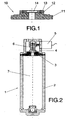
- To complement this description and for the purpose of allowing for better understanding of the characteristics of the invention, a plan sheet of an illustrative and non-restrictive nature, in which the following items are represented, is attached as an integral part of these specifications:
- Figure 1 - Corresponds to a side elevation view, duly cross-sectioned, of the object of the invention at its maximum dimensions, in other words, in a position in which the safety device using a rupture disc with multiple pressure settings has a different diameter than the one represented in figure 1, i.e., larger.
- Figure 2 - Corresponds to a cross-section view of the invention represented in a summarized form in figure 1.
-
- In accordance with the foregoing description, the safety device using a rupture disc with multiple pressure settings (1), which is made up of a cylinder or container (2) in a state of stable pressurization, referenced by (6), incorporating a pressurized chamber (7) and the hold-down device (4) supporting the rupture disk which has a gas outlet diameter (6) and is totally hermetic, has the unusual feature that if the internal pressure of the cylinder (2) rises to the higher pressure level through the effect of the ambient temperature, the rupture disc on which the hold-down device (4) is supported reaches the tensile strength limit and ruptures, allowing the gas to escape through the orifice with the diameter indicated by (6).
- However, if the cylinder (2) is in a state of stable pressurization at the respective pressure, and the actuator (6) causes the hold-down device (4) to be released so that it no longer serves as support to the rupture disc (12), the latter will rest on the ring element (13), which has a gas outlet diameter that is appreciably larger than (6). The disc is welded to this ring and to a calibrated ring referenced by (11).
- In this situation, the rupture disc (12) of the element with the larger diameter (10), reaches the limit of its tensile strength and ruptures, allowing the gas to escape through the orifice with the larger diameter (14).
- Consequently, the invention has two pressures (6) and (14) at which the single rupture disc (12) ruptures and releases the internal pressure, depending on the different orifice diameters (6) and (14) of the supporting part.
Claims (1)
- Safety device using a rupture disc with multiple pressure settings, of the type intended for use in containers or tanks, including for use in filling a car airbag, characterized in that it is made up of a metal body (2) in the form of a cylinder or vessel that is in a state of stable pressurization, with a rupture disc (12) that is supported on the hold-down device (4), which has a gas outlet diameter (6) and is totally hermetic, incorporating a ring (13) that is welded to the rupture disc (7), as well as a complementary outlet orifice (14).
Applications Claiming Priority (3)
| Application Number | Priority Date | Filing Date | Title |
|---|---|---|---|
| ES200202365U | 2002-10-03 | ||
| ES200202365U ES1052998Y (en) | 2002-10-03 | 2002-10-03 | SECURITY DEVICE THROUGH BREAK DISK WITH MULTIPLE PRESSURE PRESSURE. |
| PCT/ES2003/000269 WO2004031001A1 (en) | 2002-10-03 | 2003-06-04 | Safety device consisting of a rupture disc with multiple adjustment pressure |
Publications (1)
| Publication Number | Publication Date |
|---|---|
| EP1445157A1 true EP1445157A1 (en) | 2004-08-11 |
Family
ID=8502201
Family Applications (1)
| Application Number | Title | Priority Date | Filing Date |
|---|---|---|---|
| EP03761369A Withdrawn EP1445157A1 (en) | 2002-10-03 | 2003-06-04 | Safety device consisting of a rupture disc with multiple adjustment pressure |
Country Status (4)
| Country | Link |
|---|---|
| EP (1) | EP1445157A1 (en) |
| AU (1) | AU2003232861A1 (en) |
| ES (1) | ES1052998Y (en) |
| WO (1) | WO2004031001A1 (en) |
Family Cites Families (3)
| Publication number | Priority date | Publication date | Assignee | Title |
|---|---|---|---|---|
| GB2292210B (en) * | 1994-07-27 | 1996-12-11 | Breed Automotive Tech | Temperature compensated stored gas inflator |
| US6158769A (en) * | 1998-05-29 | 2000-12-12 | Trw Inc. | Inflator slope control device |
| US7131663B1 (en) * | 1999-08-10 | 2006-11-07 | Trw Vehicle Safety Systems Inc. | Inflator for inflatable vehicle occupant protection device |
-
2002
- 2002-10-03 ES ES200202365U patent/ES1052998Y/en not_active Expired - Fee Related
-
2003
- 2003-06-04 EP EP03761369A patent/EP1445157A1/en not_active Withdrawn
- 2003-06-04 AU AU2003232861A patent/AU2003232861A1/en not_active Abandoned
- 2003-06-04 WO PCT/ES2003/000269 patent/WO2004031001A1/en not_active Ceased
Non-Patent Citations (1)
| Title |
|---|
| See references of WO2004031001A1 * |
Also Published As
| Publication number | Publication date |
|---|---|
| ES1052998Y (en) | 2003-06-16 |
| ES1052998U (en) | 2003-03-01 |
| WO2004031001A1 (en) | 2004-04-15 |
| AU2003232861A1 (en) | 2004-04-23 |
Similar Documents
| Publication | Publication Date | Title |
|---|---|---|
| JP5774659B2 (en) | Pressure gauge | |
| EP1323928A1 (en) | Accumulator having a safety valve | |
| EP2634465A1 (en) | Controlled safety pressure response system | |
| JP2010503801A (en) | Pressure vessel | |
| US7870865B2 (en) | Safety pressure relief device | |
| JPH09119539A (en) | Piston type heat or pressure reaction safety device | |
| US4347942A (en) | Pressure relief device and method of fabrication thereof | |
| US5791367A (en) | Pressure relief device | |
| CA2927682C (en) | Systems and methods for cascading burst discs | |
| CN202252231U (en) | Valve cap device for fluid regulator | |
| CN104379468B (en) | Pressure relief devices for pressurized vessels | |
| JP2003527267A (en) | Device that alerts the pressure state in the tire | |
| JP2015522776A (en) | Pressure release valve | |
| EP1725412B1 (en) | Wheel having temperature compensated and controlled pressure | |
| US3622051A (en) | Aerosol can with overpressure venting and entrapping means | |
| US20050067025A1 (en) | Safety valve for pressurized tanks, and a tank provided with said valve | |
| CN103016802B (en) | Relief valve | |
| JP2013522556A (en) | Safety device for over temperature | |
| US9822930B2 (en) | Protection structure for gas cylinder and valve replacement | |
| US20140109823A1 (en) | Tank Pressure Indicator | |
| US4819683A (en) | Pressure relief device | |
| EP1418372A1 (en) | Thermally activated relief valve | |
| US5404746A (en) | Post depressurization indicator | |
| WO2004031001A1 (en) | Safety device consisting of a rupture disc with multiple adjustment pressure | |
| US20060175703A1 (en) | Thermally responsive pressure relief plug and method of making the same |
Legal Events
| Date | Code | Title | Description |
|---|---|---|---|
| PUAI | Public reference made under article 153(3) epc to a published international application that has entered the european phase |
Free format text: ORIGINAL CODE: 0009012 |
|
| 17P | Request for examination filed |
Effective date: 20031126 |
|
| AK | Designated contracting states |
Kind code of ref document: A1 Designated state(s): AT BE BG CH CY CZ DE DK EE ES FI FR GB GR HU IE IT LI LU MC NL PT RO SE SI SK TR |
|
| AX | Request for extension of the european patent |
Extension state: AL LT LV MK |
|
| 17Q | First examination report despatched |
Effective date: 20040915 |
|
| STAA | Information on the status of an ep patent application or granted ep patent |
Free format text: STATUS: THE APPLICATION IS DEEMED TO BE WITHDRAWN |
|
| 18D | Application deemed to be withdrawn |
Effective date: 20050126 |