EP1445099A1 - Sensor - Google Patents
Sensor Download PDFInfo
- Publication number
- EP1445099A1 EP1445099A1 EP03405068A EP03405068A EP1445099A1 EP 1445099 A1 EP1445099 A1 EP 1445099A1 EP 03405068 A EP03405068 A EP 03405068A EP 03405068 A EP03405068 A EP 03405068A EP 1445099 A1 EP1445099 A1 EP 1445099A1
- Authority
- EP
- European Patent Office
- Prior art keywords
- sensor
- check system
- sheet
- anyone
- camera
- Prior art date
- Legal status (The legal status is an assumption and is not a legal conclusion. Google has not performed a legal analysis and makes no representation as to the accuracy of the status listed.)
- Withdrawn
Links
- 238000005286 illumination Methods 0.000 claims abstract description 14
- 230000003287 optical effect Effects 0.000 claims abstract description 6
- 238000007689 inspection Methods 0.000 claims description 13
- 230000006872 improvement Effects 0.000 claims description 4
- 238000011144 upstream manufacturing Methods 0.000 claims description 3
- 238000001514 detection method Methods 0.000 claims description 2
- 238000006073 displacement reaction Methods 0.000 claims description 2
- 239000000976 ink Substances 0.000 description 12
- 238000004519 manufacturing process Methods 0.000 description 5
- 238000000034 method Methods 0.000 description 5
- 230000008569 process Effects 0.000 description 5
- 230000002950 deficient Effects 0.000 description 3
- 241001269238 Data Species 0.000 description 2
- 230000009471 action Effects 0.000 description 2
- 238000004020 luminiscence type Methods 0.000 description 2
- 238000005259 measurement Methods 0.000 description 2
- 239000000872 buffer Substances 0.000 description 1
- 239000003086 colorant Substances 0.000 description 1
- 239000000428 dust Substances 0.000 description 1
- 238000011156 evaluation Methods 0.000 description 1
- 230000001939 inductive effect Effects 0.000 description 1
- 239000000314 lubricant Substances 0.000 description 1
- 239000002184 metal Substances 0.000 description 1
- 239000002245 particle Substances 0.000 description 1
- 238000009877 rendering Methods 0.000 description 1
- 239000002904 solvent Substances 0.000 description 1
- 238000001228 spectrum Methods 0.000 description 1
- 230000000007 visual effect Effects 0.000 description 1
Images


Classifications
-
- B—PERFORMING OPERATIONS; TRANSPORTING
- B41—PRINTING; LINING MACHINES; TYPEWRITERS; STAMPS
- B41F—PRINTING MACHINES OR PRESSES
- B41F33/00—Indicating, counting, warning, control or safety devices
-
- B—PERFORMING OPERATIONS; TRANSPORTING
- B41—PRINTING; LINING MACHINES; TYPEWRITERS; STAMPS
- B41F—PRINTING MACHINES OR PRESSES
- B41F11/00—Rotary presses or machines having forme cylinders carrying a plurality of printing surfaces, or for performing letterpress, lithographic, or intaglio processes selectively or in combination
- B41F11/02—Rotary presses or machines having forme cylinders carrying a plurality of printing surfaces, or for performing letterpress, lithographic, or intaglio processes selectively or in combination for securities
-
- B—PERFORMING OPERATIONS; TRANSPORTING
- B41—PRINTING; LINING MACHINES; TYPEWRITERS; STAMPS
- B41F—PRINTING MACHINES OR PRESSES
- B41F33/00—Indicating, counting, warning, control or safety devices
- B41F33/0036—Devices for scanning or checking the printed matter for quality control
-
- G—PHYSICS
- G01—MEASURING; TESTING
- G01N—INVESTIGATING OR ANALYSING MATERIALS BY DETERMINING THEIR CHEMICAL OR PHYSICAL PROPERTIES
- G01N21/00—Investigating or analysing materials by the use of optical means, i.e. using sub-millimetre waves, infrared, visible or ultraviolet light
- G01N21/84—Systems specially adapted for particular applications
- G01N21/88—Investigating the presence of flaws or contamination
- G01N21/89—Investigating the presence of flaws or contamination in moving material, e.g. running paper or textiles
- G01N21/8914—Investigating the presence of flaws or contamination in moving material, e.g. running paper or textiles characterised by the material examined
- G01N2021/8917—Paper, also ondulated
-
- G—PHYSICS
- G01—MEASURING; TESTING
- G01N—INVESTIGATING OR ANALYSING MATERIALS BY DETERMINING THEIR CHEMICAL OR PHYSICAL PROPERTIES
- G01N21/00—Investigating or analysing materials by the use of optical means, i.e. using sub-millimetre waves, infrared, visible or ultraviolet light
- G01N21/17—Systems in which incident light is modified in accordance with the properties of the material investigated
- G01N21/25—Colour; Spectral properties, i.e. comparison of effect of material on the light at two or more different wavelengths or wavelength bands
- G01N21/31—Investigating relative effect of material at wavelengths characteristic of specific elements or molecules, e.g. atomic absorption spectrometry
- G01N21/33—Investigating relative effect of material at wavelengths characteristic of specific elements or molecules, e.g. atomic absorption spectrometry using ultraviolet light
-
- G—PHYSICS
- G01—MEASURING; TESTING
- G01N—INVESTIGATING OR ANALYSING MATERIALS BY DETERMINING THEIR CHEMICAL OR PHYSICAL PROPERTIES
- G01N21/00—Investigating or analysing materials by the use of optical means, i.e. using sub-millimetre waves, infrared, visible or ultraviolet light
- G01N21/17—Systems in which incident light is modified in accordance with the properties of the material investigated
- G01N21/25—Colour; Spectral properties, i.e. comparison of effect of material on the light at two or more different wavelengths or wavelength bands
- G01N21/31—Investigating relative effect of material at wavelengths characteristic of specific elements or molecules, e.g. atomic absorption spectrometry
- G01N21/35—Investigating relative effect of material at wavelengths characteristic of specific elements or molecules, e.g. atomic absorption spectrometry using infrared light
- G01N21/359—Investigating relative effect of material at wavelengths characteristic of specific elements or molecules, e.g. atomic absorption spectrometry using infrared light using near infrared light
Definitions
- the present invention concerns a sensor, in particular a luminiscence sensor, and a check system.
- a purpose of the invention is to provide a luminescent ink checking system, capable of detecting and inspecting in real time running printed sheets of security papers, up to and above the maximum speed of the printing machine.
- a checking system should be designed with the operator in mind, so as to enable him to quickly identify defective prints and to undertake corrective action in case of under or over inking.
- a particular purpose of the invention is a sensor unit, and particularly a luminiscence sensor unit, capable of running and inspecting printing sheets in real time and to process the datas transferring the luminescent images of the sheets to a host PC.
- a sensor in particular a luminiscence sensor, comprising a plurality of optical sensor subunits, each said subunit comprising
- a luminiscence sensor in the running mode, an array of UV illumination sources excites the fluorescent or phosphorescent particles of invisible inks, inducing luminescence.
- An associated array of cameras and digital signal processor units detect and process this luminescent emission and send datas to a host PC.
- the software on this computer enables the data of the separate subunits to be merged together, displaying a single image of the inspected sheet.
- the subunits are lined up in a row, whose length is sufficient to sense and inspect sheets having the maximal width feedable to the printing machine.
- the array of subunits is lodged within a common sealed housing equipped with UV transparent windows. Since the housing is sealed, the sensor's delicate interior is protected from dust, lubricants and all solvents that are generally present inside a printing machine.
- Suitable digital camera means include CMOS cameras.
- the signal issued by each subunit-camera is processed by a digital signal processor unit.
- the DSP unit is connected to an interface, said interface comprising a fire wire bus, connecting all the DSP units to an external computer.
- each optical sensor subunit may comprise a parabolic mirror for collecting light emitted by the inspected sample. This light is focused and sent to a counter-mirror, that in turn reflects said light and sends it through an objective of the camera head onto the photosensor of the camera head.
- the present invention offers an improvement for sheet fed security paper printing machines, namely the improvement consisting in a check system for detection and inspection of ink prints, in particular luminescent ink prints, said check system comprising a sensor, in particular a luminiscence sensor, as described above, associated to computer means connected to said sensor by an interface, thereby comparing an acquired image of each of the printed sheets to programmed set values, in particular a set image of one said sheet.
- the check system may comprise an incremental encoder for identifying sheets and localising eventual misprints and a sheet presence detector for triggering the checking and inspecting operations.
- the check system may comprise an additional UV illumination means.
- This extra illumination unit may consist of an array of UV tubes directed to the zone underneath the sensor.
- the luminiscence sensor housing containing the sensor subunits lined up in a row, is arranged so that said row is parallel to the printed sheets and oriented crosswise to the direction of displacement of said sheets.
- the accuracy of the measurement and quality of image of a sheet may be further enhanced by arranging a suction plate parallely to the row of sensor subunits, beneath the printed sheet, thereby rendering the measurement distance constant.
- the luminiscence sensor housing and the suction plate, facing one another may be arranged in any position after the application of the luminescent ink, for example within a delivery section of the printing machine, in particular just upstream of a first delivery pile. This will allow the deviation of sheets containing defective print to be sent to a separate inspection pile using the interface between the sensor and the machine.
- Fig. 1 shows that in an existing sheet fed printing machine, a check system according to the invention may be provided as an improvement, downstream of the printing section itself, within the delivery section of the printed sheets, just upstream the first delivery pile.
- Fig. 1 shows schematically the position of the luminiscence sensor housing 1 above the track of the printed sheets and the position of the suction plate 20, facing the sensor housing 1, and located just beneath the track of the sheets, thereby providing a constant distance between the surface of the inspected sheet and the luminiscence sensor.
- Fig. 2 is a photograph illustrating the arrangement of the luminiscence sensor housing and of the suction plate within a commercially available printing machine, a sheet-fed rotary letter press numbering machine of the type SuperNumerota 212 of the manufacturer KBA-GIORI.
- the length of the luminiscence sensor is adjusted so as to cover the full width of the sheet track, the full length of the sensor housing is slightly greater than 800 mm.
- the number of optical sensor subunits, in this case five subunits, is selected so as to cover a total inspection length of about 800 mm with a slight overlapping of the inspected fields by the respective subunits, the field covered per camera/DSP subunit being slightly greater than 160 mm.
- the suction plate shown by Fig. 2 consists of a perforated sheet metal plate, an array fan sucking the passing sheet down to the plate, ensuring a constant sheet-to-sensor distance.
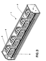
- Fig. 3 shows a perspective view of the sensor housing 1, the upper cover being removed for the sake of clarity.
- Each sensor subunit 2 comprises, as an illumination unit 3, a UV-LED emitting system, for example a light at 375 nm.
- each subunit comprises further a parabolic mirror 4 and a counter mirror 5 facing a camera head 6.
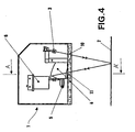
- Fig. 4 illustrates schematically the light path from the LED 3 to the running sheet 7 re-emitting fluorescent or phosphorescent light onto the parabolic mirror 4, which focuses the received light onto the counter mirror 5, which in turn reflects said light into the camera head.
- Light is received onto the optical sensor of each CMOS camera through a 6-mm objective.
- each subunit 2 comprises a complete camera unit 8 and a DSP unit 9.
- CMOS cameras and DSP units are commercially available.
- the light emitted by the LED 3 crosses a UV transparent window 10 to reach the sheet and the re-emitted light penetrates back into the housing through the window 11.
- Fig. 5 shows that the array of five subunits permits to sense the full width of sheet 7.
- the row of five autonomous cameras and DSP units is connected to a host PC through a fire wire bus for data connection and also to a separate power supply and to the sheet start and align impulse devices.
- the above-described arrangement of the five units allows a complete and continuous inspection line over a total width of slightly more than 800 mm.
- the sensor is optimised for an inspection distance from the sheet surface of 100 mm.
- the system can be easily adapted to other distances.
- the check system comprises further an incremental encoder (not shown in the drawings), mounted on a transport cylinder, which rotates once per sheet.
- the presence of a sheet is controlled by a photoelectric proximity switch.
- a separate controller unit mounted in an operator's control desk guarantees a constant vertical resolution, for example 0.5 mm, on the basis of the output of these two components.
- a controller unit provides a start signal for each sheet and an impulse for every line of the passing sheet to the luminiscence sensor. The impulses are only generated if a sheet is present.
- a control desk serves as an interface to the sensor for the operator. It is equipped with a PC, a flat screen, keyboard and mouse, allowing the set-up and handling of the sensor unit. Additionally, signal lamps may be mounted on the desk, indicating the actual state of the sensor, for example a blue light, showing whether the inspection is active or not, a green, orange and red lamp serving as a visual alarm, and reporting deviations from the acceptable limits during the printing process.
- the control desk may further bear various commands and buttons allowing to cut the power from the sensor, the illumination and the encoder controller unit.
- the control desk also houses an uninterruptible power supply, which buffers potential power cut-offs.
- the PC housed also in the control desk, may be equipped with a CD writer to backup check set-up data. Further power supplies and relays are provided in the control desk for empowering the warning lamps on the desk and the above-mentioned controller units.
- the user interface of the check system is provided with the following functions:
- the sensor set-up has only to be done once, before the very first operation, and remains the same for the lifetime of a particular sensor.
- a reference sheet is acquired and recorded and the various regions of interest (ROI) and their parameters are set.
- ROI regions of interest
- the general layout of the bank notes or other security papers is also defined and distributed on the sheet according to the entered number of columns and rows. A fine adjustment of the layout can be done manually.
- the regions of interest (ROI) can be defined for a single bank-note/security paper and are then copied automatically to all other according columns and rows.
- A-first one is adapted for the evaluation of ROIs 22 of cliché type. It computes the average intensity of the defined ROI area and compares this average with thresholds defined by the operator.
- a second algorithm detects barcodes within a defined ROI 23 and compares them with a master template.
- the check system software displays the actual states of the different ROIs in a clear manner and constantly informs the printer about possible problems of the printing process.
- the software also plots tendencies of under or over inking allowing the printer to undertake corrective action even before defective print is produced. Inspection results are displayed in real time with alarm warning and good inspection identification.
- the main window 21 gives an overview of the sheet.
- the momentary ROIs' states 22 and 23 are visualised with coloured frames, which are updated after every sheet. The frames are green as long as everything is okay and the average values of the ROIs are within the set thresholds or the barcodes are recognised correctly.
- the production monitor window 24 shows tendencies of the printing process. It displays the results of the last sheets. Five parameters are showed: the number of general errors, the number of "low” warnings, the number of "low” errors, the number of "high” warnings, the number of "high” errors per sheet, and the number of barcode error. Barcode errors occur whenever the IF Sensor detects no or a wrong barcode.
- the illumination means may also be selected among visible or IR-illumination sources, and that the appropriate corresponding camera-photosensors may detect light re-emitted by prints, e.g. images, printed by means of iridescent inks or invisible inks emitting IR wavelengths.
Priority Applications (10)
| Application Number | Priority Date | Filing Date | Title |
|---|---|---|---|
| EP03405068A EP1445099A1 (de) | 2003-02-10 | 2003-02-10 | Sensor |
| RU2005128279/12A RU2335403C2 (ru) | 2003-02-10 | 2004-02-04 | Сенсорное устройство |
| DE602004005678T DE602004005678T2 (de) | 2003-02-10 | 2004-02-04 | Sensorvorrichtung |
| US10/544,906 US7550745B2 (en) | 2003-02-10 | 2004-02-04 | Sensing device |
| CNB2004800039006A CN100396485C (zh) | 2003-02-10 | 2004-02-04 | 感测设备 |
| KR1020057014607A KR101025359B1 (ko) | 2003-02-10 | 2004-02-04 | 감지 장치 |
| AT04707861T ATE358582T1 (de) | 2003-02-10 | 2004-02-04 | Sensorvorrichtung |
| EP04707861A EP1597079B1 (de) | 2003-02-10 | 2004-02-04 | Sensorvorrichtung |
| PCT/CH2004/000057 WO2004069541A1 (en) | 2003-02-10 | 2004-02-04 | Sensing device |
| JP2006501443A JP2006518454A (ja) | 2003-02-10 | 2004-02-04 | 検知装置 |
Applications Claiming Priority (1)
| Application Number | Priority Date | Filing Date | Title |
|---|---|---|---|
| EP03405068A EP1445099A1 (de) | 2003-02-10 | 2003-02-10 | Sensor |
Publications (1)
| Publication Number | Publication Date |
|---|---|
| EP1445099A1 true EP1445099A1 (de) | 2004-08-11 |
Family
ID=32605486
Family Applications (2)
| Application Number | Title | Priority Date | Filing Date |
|---|---|---|---|
| EP03405068A Withdrawn EP1445099A1 (de) | 2003-02-10 | 2003-02-10 | Sensor |
| EP04707861A Expired - Lifetime EP1597079B1 (de) | 2003-02-10 | 2004-02-04 | Sensorvorrichtung |
Family Applications After (1)
| Application Number | Title | Priority Date | Filing Date |
|---|---|---|---|
| EP04707861A Expired - Lifetime EP1597079B1 (de) | 2003-02-10 | 2004-02-04 | Sensorvorrichtung |
Country Status (9)
| Country | Link |
|---|---|
| US (1) | US7550745B2 (de) |
| EP (2) | EP1445099A1 (de) |
| JP (1) | JP2006518454A (de) |
| KR (1) | KR101025359B1 (de) |
| CN (1) | CN100396485C (de) |
| AT (1) | ATE358582T1 (de) |
| DE (1) | DE602004005678T2 (de) |
| RU (1) | RU2335403C2 (de) |
| WO (1) | WO2004069541A1 (de) |
Cited By (4)
| Publication number | Priority date | Publication date | Assignee | Title |
|---|---|---|---|---|
| DE102006025324A1 (de) * | 2006-05-31 | 2007-12-13 | Koenig & Bauer Aktiengesellschaft | Sensoreinrichtung |
| WO2009030465A1 (de) | 2007-09-05 | 2009-03-12 | Manroland Ag | Druckmaschine |
| EP2127878A1 (de) | 2008-05-27 | 2009-12-02 | manroland AG | Verfahren zur Ermittlung von Parametern eines Druckprozesses mittels Kameras, Beuleuchtungsmodule und eines Testmusters |
| NL2009786C2 (nl) * | 2012-11-09 | 2014-05-12 | Q I Press Controls Holding B V | Camera systeem, kleurenmeetsysteem en drukpers. |
Families Citing this family (11)
| Publication number | Priority date | Publication date | Assignee | Title |
|---|---|---|---|---|
| ITVR20060185A1 (it) * | 2006-12-01 | 2008-06-02 | G M P S R L | Dispositivo di controllo per macchina numeratrice adibita alla stampa di numerazioni progressive o regressive su banconote, biglietti della lotteria, carte valori in generale |
| US8068674B2 (en) * | 2007-09-04 | 2011-11-29 | Evolution Robotics Retail, Inc. | UPC substitution fraud prevention |
| CA2711102C (en) * | 2007-12-28 | 2013-10-01 | Scientific Games Holdings Limited | System and method for detecting compromised instant lottery tickets |
| DE102008001479A1 (de) | 2008-04-30 | 2009-11-05 | Robert Bosch Gmbh | Elektrowerkzeugmaschine |
| DE102009009773A1 (de) | 2009-02-20 | 2010-08-26 | Prehkeytec Gmbh | Tastatur mit Mitteln zur Anzeige von Sicherheitsmerkmalen von Banknoten |
| JP5959001B2 (ja) * | 2012-07-20 | 2016-08-02 | 株式会社小森コーポレーション | シート状物の検査装置 |
| FI20155643A (fi) | 2015-09-08 | 2017-03-09 | Procemex Oy Ltd | Fluoresoivan nesteen optinen havainnointi puukuiturainasta |
| FR3063542A1 (fr) | 2017-03-01 | 2018-09-07 | Maf Agrobotic | Procede et dispositif d'analyse optique de fruits ou legumes et dispositif de tri automatique |
| US10358307B1 (en) * | 2018-03-28 | 2019-07-23 | Xerox Corporation | Leading/trailing edge detection system having vacuum belt with perforations |
| DE102019118000A1 (de) | 2019-07-03 | 2021-01-07 | Bundesdruckerei Gmbh | Verfahren zum Überprüfen eines Sicherheitsmerkmals in einem Halbzeug |
| CN111137032B (zh) * | 2020-01-17 | 2021-06-22 | 南京驭逡通信科技有限公司 | 智能纸张选择抽取系统 |
Citations (6)
| Publication number | Priority date | Publication date | Assignee | Title |
|---|---|---|---|---|
| US4451521A (en) * | 1980-05-30 | 1984-05-29 | Gao Gesellschaft Fur Automation Und Organisation Mbh | Security paper with authenticity features in the form of substances luminescing only in the invisible region of the optical spectrum and process for testing the same |
| US4893558A (en) * | 1986-05-12 | 1990-01-16 | Crosfield Electronics (Usa) Limited | Image reproduction |
| GB2282565A (en) * | 1993-09-22 | 1995-04-12 | Rockwell International Corp | Registration in a multi-colour printing press |
| US6024018A (en) * | 1997-04-03 | 2000-02-15 | Intex Israel Technologies Corp., Ltd | On press color control system |
| EP1149703A2 (de) * | 2000-04-26 | 2001-10-31 | Dainippon Screen Mfg. Co., Ltd. | Verfahren und Vorrichtung zum Color-Management, und Bilddatenverarbeitungs-Einrichtung |
| WO2002065107A2 (en) * | 2001-02-09 | 2002-08-22 | Wintriss Engineering Corporation | Web inspection system |
Family Cites Families (26)
| Publication number | Priority date | Publication date | Assignee | Title |
|---|---|---|---|---|
| US3105908A (en) * | 1963-10-01 | burkhardt etal | ||
| US3522432A (en) * | 1967-11-24 | 1970-08-04 | Colgate Palmolive Co | Scanning apparatus for registration marks using ultra-violet light |
| GB8311795D0 (en) * | 1983-04-29 | 1983-06-02 | De La Rue Syst | Detecting luminescent security features |
| JPS6464090A (en) * | 1987-04-30 | 1989-03-09 | Laurel Bank Machine Co | Discriminator for paper money counting machine |
| US5172005A (en) * | 1991-02-20 | 1992-12-15 | Pressco Technology, Inc. | Engineered lighting system for tdi inspection comprising means for controlling lighting elements in accordance with specimen displacement |
| JP2915294B2 (ja) * | 1993-10-27 | 1999-07-05 | 川崎製鉄株式会社 | 金属材料表面の塗油量測定方法および装置 |
| IT1269506B (it) * | 1994-02-04 | 1997-04-01 | De La Rue Giori Sa | Impianto di controllo di qualita' di fogli stampati in particolare di carte-valore |
| JP3574219B2 (ja) * | 1995-04-28 | 2004-10-06 | グローリー工業株式会社 | 真偽鑑別装置 |
| GB9517796D0 (en) * | 1995-08-31 | 1995-11-01 | At & T Global Inf Solution | A bank note scanner |
| US5815174A (en) * | 1996-01-19 | 1998-09-29 | Videojet Systems International, Inc. | System and method of thermally verifying freshly printed images |
| IT1284432B1 (it) * | 1996-03-22 | 1998-05-21 | De La Rue Giori Sa | Procedimento di controllo automatico della qualita' di stampa di un'immagine policroma |
| JPH1097663A (ja) * | 1996-09-24 | 1998-04-14 | Toyo Commun Equip Co Ltd | 紙葉類識別装置 |
| DE19844495B4 (de) * | 1998-09-29 | 2005-04-07 | Man Roland Druckmaschinen Ag | Verfahren zur Farbkalibrierung mittels Colormanagement für eine digital ansteuerbare Druckmaschine mit einer wiederbeschreibbaren Druckform |
| JP2001052232A (ja) * | 1999-08-10 | 2001-02-23 | Fuji Electric Co Ltd | 紙葉類真偽識別装置 |
| JP2002197506A (ja) * | 2000-12-26 | 2002-07-12 | Glory Ltd | Uv・蛍光検出装置及びそのセンシング方法 |
| JP2002202266A (ja) * | 2000-12-28 | 2002-07-19 | Toyo Ink Mfg Co Ltd | 印刷物の検査方法およびその装置並びにその方法に使用する検出装置 |
| JP2002214360A (ja) * | 2001-01-19 | 2002-07-31 | Hamamatsu Photonics Kk | 光検出装置 |
| CN2512040Y (zh) * | 2001-06-28 | 2002-09-18 | 上海印钞厂 | 多功能钞票印刷质量检测装置 |
| US6998623B2 (en) * | 2002-02-28 | 2006-02-14 | Nidec Copal Corporation | Sheets fluorescence detecting sensor |
| US7017492B2 (en) * | 2003-03-10 | 2006-03-28 | Quad/Tech, Inc. | Coordinating the functioning of a color control system and a defect detection system for a printing press |
| GB0314883D0 (en) * | 2003-06-26 | 2003-07-30 | Ncr Int Inc | Security labelling |
| DE10332212A1 (de) * | 2003-07-16 | 2005-02-24 | Koenig & Bauer Ag | Vorrichtungen zur Qualitätsprüfung von Prüfkörpern und ein Verfahren zum Prüfen der Qualität von Bogen |
| US7321423B2 (en) * | 2003-08-15 | 2008-01-22 | Photon, Inc. | Real-time goniospectrophotometer |
| US7337960B2 (en) * | 2004-02-27 | 2008-03-04 | Evolution Robotics, Inc. | Systems and methods for merchandise automatic checkout |
| US7170666B2 (en) * | 2004-07-27 | 2007-01-30 | Hewlett-Packard Development Company, L.P. | Nanostructure antireflection surfaces |
| US7438378B2 (en) * | 2004-08-30 | 2008-10-21 | Pitney Bowes Inc. | Fluorescent ink detector |
-
2003
- 2003-02-10 EP EP03405068A patent/EP1445099A1/de not_active Withdrawn
-
2004
- 2004-02-04 CN CNB2004800039006A patent/CN100396485C/zh not_active Expired - Fee Related
- 2004-02-04 RU RU2005128279/12A patent/RU2335403C2/ru not_active IP Right Cessation
- 2004-02-04 AT AT04707861T patent/ATE358582T1/de active
- 2004-02-04 JP JP2006501443A patent/JP2006518454A/ja active Pending
- 2004-02-04 WO PCT/CH2004/000057 patent/WO2004069541A1/en active IP Right Grant
- 2004-02-04 KR KR1020057014607A patent/KR101025359B1/ko not_active IP Right Cessation
- 2004-02-04 EP EP04707861A patent/EP1597079B1/de not_active Expired - Lifetime
- 2004-02-04 US US10/544,906 patent/US7550745B2/en not_active Expired - Fee Related
- 2004-02-04 DE DE602004005678T patent/DE602004005678T2/de not_active Expired - Lifetime
Patent Citations (6)
| Publication number | Priority date | Publication date | Assignee | Title |
|---|---|---|---|---|
| US4451521A (en) * | 1980-05-30 | 1984-05-29 | Gao Gesellschaft Fur Automation Und Organisation Mbh | Security paper with authenticity features in the form of substances luminescing only in the invisible region of the optical spectrum and process for testing the same |
| US4893558A (en) * | 1986-05-12 | 1990-01-16 | Crosfield Electronics (Usa) Limited | Image reproduction |
| GB2282565A (en) * | 1993-09-22 | 1995-04-12 | Rockwell International Corp | Registration in a multi-colour printing press |
| US6024018A (en) * | 1997-04-03 | 2000-02-15 | Intex Israel Technologies Corp., Ltd | On press color control system |
| EP1149703A2 (de) * | 2000-04-26 | 2001-10-31 | Dainippon Screen Mfg. Co., Ltd. | Verfahren und Vorrichtung zum Color-Management, und Bilddatenverarbeitungs-Einrichtung |
| WO2002065107A2 (en) * | 2001-02-09 | 2002-08-22 | Wintriss Engineering Corporation | Web inspection system |
Cited By (7)
| Publication number | Priority date | Publication date | Assignee | Title |
|---|---|---|---|---|
| DE102006025324A1 (de) * | 2006-05-31 | 2007-12-13 | Koenig & Bauer Aktiengesellschaft | Sensoreinrichtung |
| EP1862309A3 (de) * | 2006-05-31 | 2008-05-28 | Koenig & Bauer Aktiengesellschaft | Sensoreinrichtung |
| WO2009030465A1 (de) | 2007-09-05 | 2009-03-12 | Manroland Ag | Druckmaschine |
| EP2127878A1 (de) | 2008-05-27 | 2009-12-02 | manroland AG | Verfahren zur Ermittlung von Parametern eines Druckprozesses mittels Kameras, Beuleuchtungsmodule und eines Testmusters |
| NL2009786C2 (nl) * | 2012-11-09 | 2014-05-12 | Q I Press Controls Holding B V | Camera systeem, kleurenmeetsysteem en drukpers. |
| WO2014073962A1 (en) * | 2012-11-09 | 2014-05-15 | Q.I. Press Controls Holding B.V. | Camera, colour measuring system, and offset printing press |
| US9531936B2 (en) | 2012-11-09 | 2016-12-27 | Q.I. Press Controls Holding B.V. | Camera system, colour measuring system, and offset printing press |
Also Published As
| Publication number | Publication date |
|---|---|
| EP1597079A1 (de) | 2005-11-23 |
| DE602004005678D1 (de) | 2007-05-16 |
| US7550745B2 (en) | 2009-06-23 |
| RU2335403C2 (ru) | 2008-10-10 |
| JP2006518454A (ja) | 2006-08-10 |
| EP1597079B1 (de) | 2007-04-04 |
| US20060144266A1 (en) | 2006-07-06 |
| CN1747836A (zh) | 2006-03-15 |
| KR101025359B1 (ko) | 2011-03-28 |
| DE602004005678T2 (de) | 2007-12-27 |
| RU2005128279A (ru) | 2006-02-27 |
| ATE358582T1 (de) | 2007-04-15 |
| KR20050106002A (ko) | 2005-11-08 |
| CN100396485C (zh) | 2008-06-25 |
| WO2004069541A1 (en) | 2004-08-19 |
Similar Documents
| Publication | Publication Date | Title |
|---|---|---|
| EP1445099A1 (de) | Sensor | |
| US6335978B1 (en) | Variable printing system and method with optical feedback | |
| JP4272561B2 (ja) | 印刷機のための像検査システム | |
| RU2348978C2 (ru) | Устройства для контроля качества листов | |
| US6644764B2 (en) | Integrated printing/scanning system using invisible ink for document tracking | |
| KR101953725B1 (ko) | 은행권 및 유사한 인쇄 증권들의 제작을 위한 인쇄된 시트들의 오프라인 검사 및 컬러 측정을 위한 장치 | |
| JP2007523761A (ja) | 複数のモジュールを有する、シートを加工するための機械 | |
| US20100039510A1 (en) | Method and DEVICE for PRINT INSPECTION | |
| US20080049972A1 (en) | Mail imaging system with secondary illumination/imaging window | |
| JP2019040315A (ja) | 不可視特性検知装置、シート識別装置、シート処理装置、印刷検査装置、及び不可視特性検知方法 | |
| US20080019563A1 (en) | Mail processing system with low resolution UV imaging subsystem | |
| JP2012027810A (ja) | 機能性検査装置 | |
| US20080011654A1 (en) | Mail processing system with radiation filtering | |
| JP2000221142A (ja) | 品質検査装置 | |
| CN209287770U (zh) | 品检机 | |
| JP4467284B2 (ja) | カード材料表面検査装置 | |
| JP3120554B2 (ja) | 印刷における見当合せ方法及びその装置 | |
| EP3293008B1 (de) | Druckverfahren und -vorrichtung | |
| JP2009160816A (ja) | 版面又はブランケットの印刷機上検査方法 | |
| JP4153727B2 (ja) | 投票用紙分類装置の状態確認方法および装置 | |
| US20080012981A1 (en) | Mail processing system with dual camera assembly | |
| JP2017007122A (ja) | 撮像部一体型インクジェット記録装置 | |
| JP2000263762A (ja) | 新聞紙面検査装置 | |
| CN113424054A (zh) | 照明装置和检查装置 | |
| JPH0353968A (ja) | プリンタのインクリボン交換時期検知装置 |
Legal Events
| Date | Code | Title | Description |
|---|---|---|---|
| PUAI | Public reference made under article 153(3) epc to a published international application that has entered the european phase |
Free format text: ORIGINAL CODE: 0009012 |
|
| AK | Designated contracting states |
Kind code of ref document: A1 Designated state(s): AT BE BG CH CY CZ DE DK EE ES FI FR GB GR HU IE IT LI LU MC NL PT SE SI SK TR |
|
| AX | Request for extension of the european patent |
Extension state: AL LT LV MK RO |
|
| AKX | Designation fees paid | ||
| REG | Reference to a national code |
Ref country code: DE Ref legal event code: 8566 |
|
| STAA | Information on the status of an ep patent application or granted ep patent |
Free format text: STATUS: THE APPLICATION IS DEEMED TO BE WITHDRAWN |
|
| 18D | Application deemed to be withdrawn |
Effective date: 20050212 |