EP1445014A2 - Fluid storage tank - Google Patents
Fluid storage tank Download PDFInfo
- Publication number
- EP1445014A2 EP1445014A2 EP04250481A EP04250481A EP1445014A2 EP 1445014 A2 EP1445014 A2 EP 1445014A2 EP 04250481 A EP04250481 A EP 04250481A EP 04250481 A EP04250481 A EP 04250481A EP 1445014 A2 EP1445014 A2 EP 1445014A2
- Authority
- EP
- European Patent Office
- Prior art keywords
- fluid
- nozzle
- chamber
- roof
- flow
- Prior art date
- Legal status (The legal status is an assumption and is not a legal conclusion. Google has not performed a legal analysis and makes no representation as to the accuracy of the status listed.)
- Granted
Links
Images
Classifications
-
- B—PERFORMING OPERATIONS; TRANSPORTING
- B01—PHYSICAL OR CHEMICAL PROCESSES OR APPARATUS IN GENERAL
- B01F—MIXING, e.g. DISSOLVING, EMULSIFYING OR DISPERSING
- B01F23/00—Mixing according to the phases to be mixed, e.g. dispersing or emulsifying
- B01F23/40—Mixing liquids with liquids; Emulsifying
- B01F23/45—Mixing liquids with liquids; Emulsifying using flow mixing
- B01F23/452—Mixing liquids with liquids; Emulsifying using flow mixing by uniting flows taken from different parts of a receptacle or silo; Sandglass-type mixing
-
- B—PERFORMING OPERATIONS; TRANSPORTING
- B01—PHYSICAL OR CHEMICAL PROCESSES OR APPARATUS IN GENERAL
- B01F—MIXING, e.g. DISSOLVING, EMULSIFYING OR DISPERSING
- B01F25/00—Flow mixers; Mixers for falling materials, e.g. solid particles
- B01F25/20—Jet mixers, i.e. mixers using high-speed fluid streams
- B01F25/21—Jet mixers, i.e. mixers using high-speed fluid streams with submerged injectors, e.g. nozzles, for injecting high-pressure jets into a large volume or into mixing chambers
-
- B—PERFORMING OPERATIONS; TRANSPORTING
- B01—PHYSICAL OR CHEMICAL PROCESSES OR APPARATUS IN GENERAL
- B01F—MIXING, e.g. DISSOLVING, EMULSIFYING OR DISPERSING
- B01F25/00—Flow mixers; Mixers for falling materials, e.g. solid particles
- B01F25/20—Jet mixers, i.e. mixers using high-speed fluid streams
- B01F25/21—Jet mixers, i.e. mixers using high-speed fluid streams with submerged injectors, e.g. nozzles, for injecting high-pressure jets into a large volume or into mixing chambers
- B01F25/212—Jet mixers, i.e. mixers using high-speed fluid streams with submerged injectors, e.g. nozzles, for injecting high-pressure jets into a large volume or into mixing chambers the injectors being movable, e.g. rotating
-
- B—PERFORMING OPERATIONS; TRANSPORTING
- B01—PHYSICAL OR CHEMICAL PROCESSES OR APPARATUS IN GENERAL
- B01F—MIXING, e.g. DISSOLVING, EMULSIFYING OR DISPERSING
- B01F25/00—Flow mixers; Mixers for falling materials, e.g. solid particles
- B01F25/30—Injector mixers
- B01F25/31—Injector mixers in conduits or tubes through which the main component flows
- B01F25/312—Injector mixers in conduits or tubes through which the main component flows with Venturi elements; Details thereof
-
- B—PERFORMING OPERATIONS; TRANSPORTING
- B01—PHYSICAL OR CHEMICAL PROCESSES OR APPARATUS IN GENERAL
- B01F—MIXING, e.g. DISSOLVING, EMULSIFYING OR DISPERSING
- B01F25/00—Flow mixers; Mixers for falling materials, e.g. solid particles
- B01F25/50—Circulation mixers, e.g. wherein at least part of the mixture is discharged from and reintroduced into a receptacle
Definitions
- the present invention relates to a fluid storage tank and, more particularly to an oil tank comprising means for inhibiting or dispersing a build-up of sludge therein.
- the chamber roof is typically provided with a plurality of legs, which support the roof above the floor of the chamber, when the chamber is emptied, to allow access to the interior of the base region of the tank for cleaning or maintenance.
- solid or semi-solid materials it is common for solid or semi-solid materials to accumulate in the base of such a tank, when it is used to store certain fluids, e.g. oil, thereby preventing the legs of the chamber roof from landing securely upon the base of the chamber when the chamber is emptied, or at least impeding access to the interior of the base region of the tank, for removing the accumulated material therefrom.
- certain fluids e.g. oil
- a fluid storage tank comprising a chamber having a roof arranged to float upon a body of fluid contained in the chamber, a nozzle suspended from the roof and pumping means arranged to circulate a flow of fluid through the chamber via the nozzle, to inhibit or disperse a build-up of solid or semi-solid materials upon the floor of the chamber, the nozzle having a tapered outlet end through which said flow of fluid issues as a jet, said outlet end being provided with a tubular shroud which is formed with apertures for drawing additional fluid from said chamber and through said nozzle.
- the nozzle Because of the arrangement of the nozzle, the nozzle has been found to be surprisingly effective in dispersing sludge and like material on the floor of the chamber.
- the nozzle is arranged to direct the outflow of fluid therefrom in a plane extending parallel to the base of the chamber.
- the nozzle is preferably arranged to rotate about a vertical axis in said parallel plane and/or may be vertically displaceable with respect to the roof.
- a plurality of legs depend from the roof for supporting the roof above the floor of the chamber, the nozzle being vertically displaceable to direct the outflow of fluid therefrom in a plane extending below the distal ends of the legs.
- the pumping means comprise means for heating the flow of fluid.
- fluid circulation means for use with a fluid storage tank comprising a chamber having a roof arranged to float upon a body of fluid contained in the chamber, the circulation means comprising a nozzle, means for suspending the nozzle from the roof and pumping means arranged to circulate a flow of fluid through the chamber via the nozzle, to inhibit or disperse a build-up of solid or semi-solid materials upon the floor of the chamber, the nozzle having a tapered outlet end through which said flow of fluid issues as a jet, said outlet end being provided with a tubular shroud which is formed with apertures for drawing additional fluid from said chamber and through said nozzle.
- the nozzle is preferably arranged to be fitted to the roof to direct the outflow of fluid therefrom in a plane extending parallel to the base of the chamber.
- the circulation means preferably comprise means for rotating the nozzle about a vertical axis in said parallel plane and/or displacing the nozzle vertically with respect to the roof.
- the pumping means preferably comprise means for heating the flow of fluid
- a method for inhibiting or disbursing a build-up of solid or semi-solid materials upon the floor of a fluid filled chamber comprising circulating a flow of fluid through the chamber via a nozzle suspended from the roof of the chamber, the roof being arranged to float upon the body of fluid contained in the chamber, and the nozzle having a tapered outlet end through which said flow of fluid issues as a jet, said outlet end being provided with a tubular shroud which is formed with apertures for drawing additional fluid from said chamber and through said nozzle.
- the nozzle directs the outflow of fluid therefrom in a plane extending parallel to the base of the chamber.
- the nozzle preferably rotates about a vertical axis in said parallel plane.
- a plurality of legs may depend from the roof for supporting the roof above the floor of the chamber, in which case, the nozzle is preferably retractably positioned to direct the outflow of fluid therefrom in a plane extending below the distal ends of the legs.
- the flow of fluid is heated, externally of the chamber, as it is circulated.
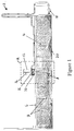
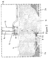
- an oil storage tank 2 comprising a chamber 4 having a roof 6 arranged to float upon a body of fluid contained in the chamber 4 and having a plurality of support legs 7 depending therefrom.
- a nozzle 8 is suspended through a manway 10 at the centre of the chamber roof 6, from a gantry 12 provided with a pulley 14 for raising and lowering the nozzle 8, and a hydraulic actuator 16 for rotating the nozzle 8 about a vertical axis in a plane extending parallel to the floor of the chamber 4.
- Pumping means 18 are arranged to draw a flow of oil from the chamber 4, to heat the flow and to re-introduce the flow into the chamber via the nozzle 8, whilst the nozzle 8 is rotated, to disperse the mounds of sludge 20 that will tend to accumulate upon the floor of the chamber 4.
- the nozzle 8 is of venturi type, comprising a tapered outlet port 22 for releasing the flow of fluid therethrough as a concentrated jet, at the same time drawing additional fluid into the jet and through the nozzle 8, via inlet apertures formed in a shroud 24 thereof.
- the floor of the chamber 4 may be cleared of sludge, thereby allowing the legs 7 of the chamber roof 6 to be landed securely on the floor of the chamber 4, as the chamber 4 is emptied.
Landscapes
- Chemical & Material Sciences (AREA)
- Chemical Kinetics & Catalysis (AREA)
- Cleaning In General (AREA)
- Filling Or Discharging Of Gas Storage Vessels (AREA)
- Buildings Adapted To Withstand Abnormal External Influences (AREA)
- Supply Devices, Intensifiers, Converters, And Telemotors (AREA)
- Engine Equipment That Uses Special Cycles (AREA)
- Other Liquid Machine Or Engine Such As Wave Power Use (AREA)
- Catching Or Destruction (AREA)
- Physical Or Chemical Processes And Apparatus (AREA)
- Treatment Of Sludge (AREA)
Abstract
Description
Claims (16)
- A fluid storage tank comprising a chamber having a roof arranged to float upon a body of fluid contained in said chamber, a nozzle suspended from said roof and pumping means arranged to circulate a flow of fluid through said chamber via said nozzle, to inhibit or disperse a build-up of solid or semi-solid materials upon the floor of said chamber, the nozzle having a tapered outlet end through which said flow of fluid issues as a jet, said outlet end being provided with a tubular shroud which is formed with apertures for drawing additional fluid from said chamber and through said nozzle.
- A fluid storage tank as claimed in Claim 1, wherein said nozzle is arranged to direct the outflow of fluid therefrom in a plane extending parallel to the base of said chamber.
- A fluid storage tank as claimed in Claim 2, wherein said nozzle is arranged to rotate about a vertical axis in said parallel plane.
- A fluid storage tank as claimed in any preceding claims, wherein said nozzle is vertically displaceable with respect to said roof.
- A fluid storage tank as claimed in any Claim 4 appended to Claim 2 or Claim 3, wherein a plurality of legs depend from said roof for supporting said roof above the floor of said chamber, said nozzle being vertically displaceable to direct the outflow of fluid therefrom in a plane extending below the distal ends of said legs.
- A fluid storage tank as claimed in any preceding claim, wherein said pumping means comprise means for heating said flow of fluid.
- Fluid circulation means for use with a fluid storage tank comprising a chamber having a roof arranged to float upon a body of fluid contained in said chamber, said circulation means comprising a nozzle, means for suspending said nozzle from said roof and pumping means arranged to circulate a flow of fluid through said chamber via said nozzle, to inhibit or disperse any build-up of solid or semi-solid materials upon the floor of said chamber, the nozzle having a tapered outlet end through which said flow of fluid issues as a jet, said outlet end being provided with a tubular shroud which is formed with apertures for drawing additional fluid from said chamber and through said nozzle.
- Fluid circulation means as claimed in Claim 7, wherein said nozzle is arranged to be fitted to said roof to direct the outflow of fluid therefrom in a plane extending parallel to the base of said chamber.
- Fluid circulation means as claimed in Claim 8, comprising means for rotating said nozzle about a vertical axis in said parallel plane.
- Fluid circulation means as claimed in any of Claims 7 to 9, comprising means for displacing said nozzle vertically with respect to said roof.
- Fluid circulation means as claimed in any of Claims 7 to 10, wherein said pumping means comprise means for heating said flow of fluid.
- A method for inhibiting or disbursing a build-up of solid or semi-solid materials upon the floor of a fluid filled chamber, comprising circulating a flow of fluid through said chamber via a nozzle suspended from the roof of the chamber, said roof being arranged to float upon the body of fluid contained in said chamber, and the nozzle having a tapered outlet end through which said flow of fluid issues as a jet, said outlet end being provided with a tubular shroud which is formed with apertures for drawing additional fluid from said chamber and through said nozzle.
- A method as claimed in Claim 12, wherein the nozzle directs the outflow of fluid therefrom in a plane extending parallel to the base of said chamber.
- A method as claimed in Claim 13, wherein said nozzle rotates about a vertical axis in said parallel plane.
- A method as claimed in Claim 13 or Claim 14, wherein a plurality of legs depend from said roof for supporting said roof above the floor of said chamber, said nozzle being retractably positioned to direct the outflow of fluid therefrom in a plane extending below the distal ends of said legs.
- A method as claimed in any of Claims 12 to 15, wherein said flow of fluid is heated, externally of said chamber, as it is circulated.
Applications Claiming Priority (2)
| Application Number | Priority Date | Filing Date | Title |
|---|---|---|---|
| GB0302794 | 2003-02-07 | ||
| GB0302794A GB2397996B (en) | 2003-02-07 | 2003-02-07 | Sludge dispersal/inhibition in floating roof storage tanks |
Publications (3)
| Publication Number | Publication Date |
|---|---|
| EP1445014A2 true EP1445014A2 (en) | 2004-08-11 |
| EP1445014A3 EP1445014A3 (en) | 2005-01-05 |
| EP1445014B1 EP1445014B1 (en) | 2007-07-25 |
Family
ID=9952599
Family Applications (1)
| Application Number | Title | Priority Date | Filing Date |
|---|---|---|---|
| EP04250481A Expired - Lifetime EP1445014B1 (en) | 2003-02-07 | 2004-01-29 | Fluid storage tank, fluid circulation means and method |
Country Status (4)
| Country | Link |
|---|---|
| EP (1) | EP1445014B1 (en) |
| AT (1) | ATE367856T1 (en) |
| DE (1) | DE602004007698D1 (en) |
| GB (1) | GB2397996B (en) |
Cited By (2)
| Publication number | Priority date | Publication date | Assignee | Title |
|---|---|---|---|---|
| NL1032428C2 (en) * | 2006-09-05 | 2008-03-06 | Verstegen Holding B V | Mixing device for mixing a liquid product with at least one ingredient. |
| EP2447698A1 (en) | 2010-11-02 | 2012-05-02 | Kimman Process Solutions B.V. | A method and system for at least temporarily homogenizing a fluid flow in a pipeline |
Family Cites Families (8)
| Publication number | Priority date | Publication date | Assignee | Title |
|---|---|---|---|---|
| US2577797A (en) * | 1950-05-23 | 1951-12-11 | Chicago Bridge & Iron Co | Mixing apparatus for tanks |
| JPS58114783A (en) * | 1981-12-28 | 1983-07-08 | タイホ−工業株式会社 | liquid injection device |
| EP0160805B1 (en) * | 1984-03-13 | 1991-12-04 | FIPROSA Holding | Method and apparatus for the recovery of crude oil or refining products from their sludge |
| US4828625A (en) * | 1987-03-09 | 1989-05-09 | Nalco Chemical Company | Apparatus and method for removal of sludge from tanks |
| DE4101184C2 (en) * | 1991-01-17 | 1994-07-14 | Sobinger Dietrich | Process and installation for cleaning floating roof tanks for storing crude oil |
| US5087294A (en) * | 1991-04-02 | 1992-02-11 | Allen Rechtzigel | Method and apparatus for cleaning a petroleum products storage tank |
| US5445173A (en) * | 1994-07-18 | 1995-08-29 | Matrix Service, Inc. | System for stirring and thereby reducing build up of bottom sediments in a storage tank |
| LU90183B1 (en) * | 1997-12-15 | 1998-04-06 | Petrojet Limited | Process for cleaning an oil tank and device for carrying out said process |
-
2003
- 2003-02-07 GB GB0302794A patent/GB2397996B/en not_active Expired - Lifetime
-
2004
- 2004-01-29 EP EP04250481A patent/EP1445014B1/en not_active Expired - Lifetime
- 2004-01-29 DE DE602004007698T patent/DE602004007698D1/en not_active Expired - Lifetime
- 2004-01-29 AT AT04250481T patent/ATE367856T1/en not_active IP Right Cessation
Cited By (3)
| Publication number | Priority date | Publication date | Assignee | Title |
|---|---|---|---|---|
| NL1032428C2 (en) * | 2006-09-05 | 2008-03-06 | Verstegen Holding B V | Mixing device for mixing a liquid product with at least one ingredient. |
| EP1897608A1 (en) | 2006-09-05 | 2008-03-12 | Verstegen Holding B.V. | Mixing device for mixing a liquid product with at least one ingredient |
| EP2447698A1 (en) | 2010-11-02 | 2012-05-02 | Kimman Process Solutions B.V. | A method and system for at least temporarily homogenizing a fluid flow in a pipeline |
Also Published As
| Publication number | Publication date |
|---|---|
| DE602004007698D1 (en) | 2007-09-06 |
| GB2397996A (en) | 2004-08-11 |
| GB0302794D0 (en) | 2003-03-12 |
| EP1445014B1 (en) | 2007-07-25 |
| ATE367856T1 (en) | 2007-08-15 |
| EP1445014A3 (en) | 2005-01-05 |
| GB2397996B (en) | 2005-01-19 |
Similar Documents
| Publication | Publication Date | Title |
|---|---|---|
| US4828625A (en) | Apparatus and method for removal of sludge from tanks | |
| US5348420A (en) | Method and arrangement for influencing liquid in ground | |
| KR200455119Y1 (en) | Stirring device for storage fluid in tank | |
| US7670482B2 (en) | Self-cleaning screen with check valve for use in shallow water pumping | |
| US5680811A (en) | Recirculating food product fryer | |
| CN100413406C (en) | Waste water separation system for liquid container | |
| KR102627973B1 (en) | Apparatus and related methods for making solutions | |
| AU2013242855A1 (en) | Device for thermally treating products with cleaning of the process liquid | |
| EP1445014B1 (en) | Fluid storage tank, fluid circulation means and method | |
| US20030057145A1 (en) | Coolant recycling system | |
| RU2374186C2 (en) | Device for purifying liquid and foam | |
| DE202006003349U1 (en) | Cleaning system e.g. for cleaning agents inserted from outside system through equipment drip pan, has door, lockable chamber, exhaust fan, heater, and flowing chamber discharging into discharge box | |
| US5938326A (en) | Combination dispersion and skimming device | |
| CZ284823B6 (en) | Apparatus for extracting peat | |
| US9713829B2 (en) | Washing apparatus | |
| US11229861B2 (en) | Sludge harvester improvements | |
| SE538367C2 (en) | Air supply device and water supply system comprising an air supply device | |
| DE2844934C2 (en) | Device for aerating manure or the like | |
| NL2014509B1 (en) | Overflow system. | |
| US20150053297A1 (en) | Container wand assembly | |
| NO20230667A1 (en) | A CO2 stripper comprising a cleaning arrangement | |
| KR200362855Y1 (en) | Disk type diffuser for the depth of water | |
| CN117282700A (en) | Washing machine for cleaning items used to house animals | |
| KR0154883B1 (en) | Fluid processing method and apparatus | |
| BE500624A (en) |
Legal Events
| Date | Code | Title | Description |
|---|---|---|---|
| PUAI | Public reference made under article 153(3) epc to a published international application that has entered the european phase |
Free format text: ORIGINAL CODE: 0009012 |
|
| AK | Designated contracting states |
Kind code of ref document: A2 Designated state(s): AT BE BG CH CY CZ DE DK EE ES FI FR GB GR HU IE IT LI LU MC NL PT RO SE SI SK TR |
|
| AX | Request for extension of the european patent |
Extension state: AL LT LV MK |
|
| PUAL | Search report despatched |
Free format text: ORIGINAL CODE: 0009013 |
|
| AK | Designated contracting states |
Kind code of ref document: A3 Designated state(s): AT BE BG CH CY CZ DE DK EE ES FI FR GB GR HU IE IT LI LU MC NL PT RO SE SI SK TR |
|
| AX | Request for extension of the european patent |
Extension state: AL LT LV MK |
|
| 17P | Request for examination filed |
Effective date: 20050202 |
|
| AKX | Designation fees paid |
Designated state(s): AT BE BG CH CY CZ DE DK EE ES FI FR GB GR HU IE IT LI LU MC NL PT RO SE SI SK TR |
|
| RTI1 | Title (correction) |
Free format text: FLUID STORAGE TANK, FLUID CIRCULATION MEANS AND METHOD |
|
| GRAP | Despatch of communication of intention to grant a patent |
Free format text: ORIGINAL CODE: EPIDOSNIGR1 |
|
| GRAS | Grant fee paid |
Free format text: ORIGINAL CODE: EPIDOSNIGR3 |
|
| GRAA | (expected) grant |
Free format text: ORIGINAL CODE: 0009210 |
|
| AK | Designated contracting states |
Kind code of ref document: B1 Designated state(s): AT BE BG CH CY CZ DE DK EE ES FI FR GB GR HU IE IT LI LU MC NL PT RO SE SI SK TR |
|
| REG | Reference to a national code |
Ref country code: GB Ref legal event code: FG4D |
|
| REG | Reference to a national code |
Ref country code: CH Ref legal event code: EP |
|
| REG | Reference to a national code |
Ref country code: IE Ref legal event code: FG4D |
|
| REF | Corresponds to: |
Ref document number: 602004007698 Country of ref document: DE Date of ref document: 20070906 Kind code of ref document: P |
|
| PG25 | Lapsed in a contracting state [announced via postgrant information from national office to epo] |
Ref country code: NL Free format text: LAPSE BECAUSE OF FAILURE TO SUBMIT A TRANSLATION OF THE DESCRIPTION OR TO PAY THE FEE WITHIN THE PRESCRIBED TIME-LIMIT Effective date: 20070725 Ref country code: BG Free format text: LAPSE BECAUSE OF FAILURE TO SUBMIT A TRANSLATION OF THE DESCRIPTION OR TO PAY THE FEE WITHIN THE PRESCRIBED TIME-LIMIT Effective date: 20071025 Ref country code: FI Free format text: LAPSE BECAUSE OF FAILURE TO SUBMIT A TRANSLATION OF THE DESCRIPTION OR TO PAY THE FEE WITHIN THE PRESCRIBED TIME-LIMIT Effective date: 20070725 Ref country code: PT Free format text: LAPSE BECAUSE OF FAILURE TO SUBMIT A TRANSLATION OF THE DESCRIPTION OR TO PAY THE FEE WITHIN THE PRESCRIBED TIME-LIMIT Effective date: 20071226 |
|
| REG | Reference to a national code |
Ref country code: CH Ref legal event code: PL |
|
| NLV1 | Nl: lapsed or annulled due to failure to fulfill the requirements of art. 29p and 29m of the patents act | ||
| PG25 | Lapsed in a contracting state [announced via postgrant information from national office to epo] |
Ref country code: AT Free format text: LAPSE BECAUSE OF FAILURE TO SUBMIT A TRANSLATION OF THE DESCRIPTION OR TO PAY THE FEE WITHIN THE PRESCRIBED TIME-LIMIT Effective date: 20070725 Ref country code: LI Free format text: LAPSE BECAUSE OF FAILURE TO SUBMIT A TRANSLATION OF THE DESCRIPTION OR TO PAY THE FEE WITHIN THE PRESCRIBED TIME-LIMIT Effective date: 20070725 Ref country code: CH Free format text: LAPSE BECAUSE OF FAILURE TO SUBMIT A TRANSLATION OF THE DESCRIPTION OR TO PAY THE FEE WITHIN THE PRESCRIBED TIME-LIMIT Effective date: 20070725 |
|
| EN | Fr: translation not filed | ||
| PG25 | Lapsed in a contracting state [announced via postgrant information from national office to epo] |
Ref country code: BE Free format text: LAPSE BECAUSE OF FAILURE TO SUBMIT A TRANSLATION OF THE DESCRIPTION OR TO PAY THE FEE WITHIN THE PRESCRIBED TIME-LIMIT Effective date: 20070725 |
|
| PG25 | Lapsed in a contracting state [announced via postgrant information from national office to epo] |
Ref country code: GR Free format text: LAPSE BECAUSE OF FAILURE TO SUBMIT A TRANSLATION OF THE DESCRIPTION OR TO PAY THE FEE WITHIN THE PRESCRIBED TIME-LIMIT Effective date: 20071026 Ref country code: DK Free format text: LAPSE BECAUSE OF FAILURE TO SUBMIT A TRANSLATION OF THE DESCRIPTION OR TO PAY THE FEE WITHIN THE PRESCRIBED TIME-LIMIT Effective date: 20070725 Ref country code: ES Free format text: LAPSE BECAUSE OF FAILURE TO SUBMIT A TRANSLATION OF THE DESCRIPTION OR TO PAY THE FEE WITHIN THE PRESCRIBED TIME-LIMIT Effective date: 20071225 |
|
| PG25 | Lapsed in a contracting state [announced via postgrant information from national office to epo] |
Ref country code: SK Free format text: LAPSE BECAUSE OF FAILURE TO SUBMIT A TRANSLATION OF THE DESCRIPTION OR TO PAY THE FEE WITHIN THE PRESCRIBED TIME-LIMIT Effective date: 20070725 Ref country code: CZ Free format text: LAPSE BECAUSE OF FAILURE TO SUBMIT A TRANSLATION OF THE DESCRIPTION OR TO PAY THE FEE WITHIN THE PRESCRIBED TIME-LIMIT Effective date: 20070725 |
|
| PLBE | No opposition filed within time limit |
Free format text: ORIGINAL CODE: 0009261 |
|
| STAA | Information on the status of an ep patent application or granted ep patent |
Free format text: STATUS: NO OPPOSITION FILED WITHIN TIME LIMIT |
|
| PG25 | Lapsed in a contracting state [announced via postgrant information from national office to epo] |
Ref country code: RO Free format text: LAPSE BECAUSE OF FAILURE TO SUBMIT A TRANSLATION OF THE DESCRIPTION OR TO PAY THE FEE WITHIN THE PRESCRIBED TIME-LIMIT Effective date: 20070725 Ref country code: SE Free format text: LAPSE BECAUSE OF FAILURE TO SUBMIT A TRANSLATION OF THE DESCRIPTION OR TO PAY THE FEE WITHIN THE PRESCRIBED TIME-LIMIT Effective date: 20071025 |
|
| 26N | No opposition filed |
Effective date: 20080428 |
|
| PG25 | Lapsed in a contracting state [announced via postgrant information from national office to epo] |
Ref country code: FR Free format text: LAPSE BECAUSE OF FAILURE TO SUBMIT A TRANSLATION OF THE DESCRIPTION OR TO PAY THE FEE WITHIN THE PRESCRIBED TIME-LIMIT Effective date: 20080321 Ref country code: DE Free format text: LAPSE BECAUSE OF FAILURE TO SUBMIT A TRANSLATION OF THE DESCRIPTION OR TO PAY THE FEE WITHIN THE PRESCRIBED TIME-LIMIT Effective date: 20071026 |
|
| PG25 | Lapsed in a contracting state [announced via postgrant information from national office to epo] |
Ref country code: MC Free format text: LAPSE BECAUSE OF NON-PAYMENT OF DUE FEES Effective date: 20080131 |
|
| PG25 | Lapsed in a contracting state [announced via postgrant information from national office to epo] |
Ref country code: IE Free format text: LAPSE BECAUSE OF NON-PAYMENT OF DUE FEES Effective date: 20080129 Ref country code: EE Free format text: LAPSE BECAUSE OF FAILURE TO SUBMIT A TRANSLATION OF THE DESCRIPTION OR TO PAY THE FEE WITHIN THE PRESCRIBED TIME-LIMIT Effective date: 20070725 |
|
| PG25 | Lapsed in a contracting state [announced via postgrant information from national office to epo] |
Ref country code: SI Free format text: LAPSE BECAUSE OF FAILURE TO SUBMIT A TRANSLATION OF THE DESCRIPTION OR TO PAY THE FEE WITHIN THE PRESCRIBED TIME-LIMIT Effective date: 20070725 |
|
| PG25 | Lapsed in a contracting state [announced via postgrant information from national office to epo] |
Ref country code: CY Free format text: LAPSE BECAUSE OF FAILURE TO SUBMIT A TRANSLATION OF THE DESCRIPTION OR TO PAY THE FEE WITHIN THE PRESCRIBED TIME-LIMIT Effective date: 20070725 |
|
| PG25 | Lapsed in a contracting state [announced via postgrant information from national office to epo] |
Ref country code: LU Free format text: LAPSE BECAUSE OF NON-PAYMENT OF DUE FEES Effective date: 20080129 Ref country code: HU Free format text: LAPSE BECAUSE OF FAILURE TO SUBMIT A TRANSLATION OF THE DESCRIPTION OR TO PAY THE FEE WITHIN THE PRESCRIBED TIME-LIMIT Effective date: 20080126 |
|
| PG25 | Lapsed in a contracting state [announced via postgrant information from national office to epo] |
Ref country code: IT Free format text: LAPSE BECAUSE OF NON-PAYMENT OF DUE FEES Effective date: 20080131 |
|
| PGFP | Annual fee paid to national office [announced via postgrant information from national office to epo] |
Ref country code: GB Payment date: 20131107 Year of fee payment: 11 |
|
| PGFP | Annual fee paid to national office [announced via postgrant information from national office to epo] |
Ref country code: TR Payment date: 20140103 Year of fee payment: 11 |
|
| GBPC | Gb: european patent ceased through non-payment of renewal fee |
Effective date: 20150129 |
|
| PG25 | Lapsed in a contracting state [announced via postgrant information from national office to epo] |
Ref country code: GB Free format text: LAPSE BECAUSE OF NON-PAYMENT OF DUE FEES Effective date: 20150129 |
|
| PG25 | Lapsed in a contracting state [announced via postgrant information from national office to epo] |
Ref country code: TR Free format text: LAPSE BECAUSE OF NON-PAYMENT OF DUE FEES Effective date: 20150129 |