EP1444923A1 - Frame system for building a shelf system - Google Patents
Frame system for building a shelf system Download PDFInfo
- Publication number
- EP1444923A1 EP1444923A1 EP04002208A EP04002208A EP1444923A1 EP 1444923 A1 EP1444923 A1 EP 1444923A1 EP 04002208 A EP04002208 A EP 04002208A EP 04002208 A EP04002208 A EP 04002208A EP 1444923 A1 EP1444923 A1 EP 1444923A1
- Authority
- EP
- European Patent Office
- Prior art keywords
- columns
- frame system
- sections
- section
- flanges
- Prior art date
- Legal status (The legal status is an assumption and is not a legal conclusion. Google has not performed a legal analysis and makes no representation as to the accuracy of the status listed.)
- Withdrawn
Links
- 210000002105 tongue Anatomy 0.000 claims description 35
- 125000006850 spacer group Chemical group 0.000 claims description 25
- 238000003466 welding Methods 0.000 claims description 3
- 230000004308 accommodation Effects 0.000 claims description 2
- 230000007797 corrosion Effects 0.000 description 10
- 238000005260 corrosion Methods 0.000 description 10
- XEEYBQQBJWHFJM-UHFFFAOYSA-N Iron Chemical compound [Fe] XEEYBQQBJWHFJM-UHFFFAOYSA-N 0.000 description 8
- 238000010276 construction Methods 0.000 description 7
- 229910000831 Steel Inorganic materials 0.000 description 5
- 239000000463 material Substances 0.000 description 5
- 239000010959 steel Substances 0.000 description 5
- 229910052742 iron Inorganic materials 0.000 description 4
- 238000004519 manufacturing process Methods 0.000 description 4
- 238000005246 galvanizing Methods 0.000 description 3
- 239000002184 metal Substances 0.000 description 3
- 229910052751 metal Inorganic materials 0.000 description 3
- 238000005034 decoration Methods 0.000 description 2
- 239000002356 single layer Substances 0.000 description 2
- 239000000126 substance Substances 0.000 description 2
- 238000005452 bending Methods 0.000 description 1
- 239000000969 carrier Substances 0.000 description 1
- 239000003086 colorant Substances 0.000 description 1
- 238000003780 insertion Methods 0.000 description 1
- 230000037431 insertion Effects 0.000 description 1
- 238000009434 installation Methods 0.000 description 1
- 239000010410 layer Substances 0.000 description 1
- 230000002787 reinforcement Effects 0.000 description 1
- 238000000926 separation method Methods 0.000 description 1
- 238000000638 solvent extraction Methods 0.000 description 1
- 230000006641 stabilisation Effects 0.000 description 1
- 230000003019 stabilising effect Effects 0.000 description 1
- 238000003860 storage Methods 0.000 description 1
- 238000006467 substitution reaction Methods 0.000 description 1
Images

Classifications
-
- A—HUMAN NECESSITIES
- A47—FURNITURE; DOMESTIC ARTICLES OR APPLIANCES; COFFEE MILLS; SPICE MILLS; SUCTION CLEANERS IN GENERAL
- A47B—TABLES; DESKS; OFFICE FURNITURE; CABINETS; DRAWERS; GENERAL DETAILS OF FURNITURE
- A47B96/00—Details of cabinets, racks or shelf units not covered by a single one of groups A47B43/00 - A47B95/00; General details of furniture
- A47B96/14—Bars, uprights, struts, or like supports, for cabinets, brackets, or the like
- A47B96/1416—Uprights receiving panels and brackets
-
- A—HUMAN NECESSITIES
- A47—FURNITURE; DOMESTIC ARTICLES OR APPLIANCES; COFFEE MILLS; SPICE MILLS; SUCTION CLEANERS IN GENERAL
- A47B—TABLES; DESKS; OFFICE FURNITURE; CABINETS; DRAWERS; GENERAL DETAILS OF FURNITURE
- A47B96/00—Details of cabinets, racks or shelf units not covered by a single one of groups A47B43/00 - A47B95/00; General details of furniture
- A47B96/06—Brackets or similar supporting means for cabinets, racks or shelves
- A47B96/061—Cantilever brackets
-
- A—HUMAN NECESSITIES
- A47—FURNITURE; DOMESTIC ARTICLES OR APPLIANCES; COFFEE MILLS; SPICE MILLS; SUCTION CLEANERS IN GENERAL
- A47F—SPECIAL FURNITURE, FITTINGS, OR ACCESSORIES FOR SHOPS, STOREHOUSES, BARS, RESTAURANTS OR THE LIKE; PAYING COUNTERS
- A47F5/00—Show stands, hangers, or shelves characterised by their constructional features
- A47F5/10—Adjustable or foldable or dismountable display stands
- A47F5/101—Display racks with slotted uprights
- A47F5/103—Display shelving racks with the uprights aligned in only one plane
Definitions
- the present invention concerns a frame system for building up a shelf system, preferably for displaying articles in shops, department stores, supermarkets and warehouses, of the kind including columns standing up vertically from a base, at least one side of which, preferably two opposed sides, including cutouts running in parallel in longitudinal direction of the column for mounting supports projecting from these, between which displays are provided, e.g.
- the columns being supported by at least one releasably attached foot member projecting from the lower end of the column and at the same side of the column from which the shelf supports are projecting, including adjustable legs, and where one end side of the foot member includes at least one projecting, first upper locking tongue interacting with cutouts in the column, and a second lower locking tongue, the downwards facing sides of which each including a slit.
- the above mentioned shelves are well-known and are used in many contexts in connection with particularly retail stores, where articles are placed on shelves disposed on the supports.
- the said shelf systems are typically constituted by columns with a closed column profile having a circular or rectangular cross-section.
- the shelf systems are typically delivered in assembly kits where column members and foot members are assembled at the site where the shelf system is to be used. It is of great importance that the said shelves are constituted by as few individual parts as possible, and furthermore that the said individual parts are readily assembled without using any special tools. Besides, it is required that the said shelf systems display statical stability, as it may be expected that the shelf systems are loaded even very heavily.
- the known shelf systems of the kind indicated including closed column profiles and partially closed foot members imply that providing an efficient corrosion protection of these metal parts made of steel or iron, e.g. by galvanising or similar, is even very difficult to accomplish within an acceptable cost level.
- the said limitations in possibilities to corrosion protect the said metal parts consequently imply limitations in the possibilities of use for the said shelves.
- it will be less suitable to use the said shelf systems in e.g. cold stores and on locations where large variations in temperature and air humidity are to be expected, as the risk of corrosion in the metal parts (columns, foot members etc.) made of steel or iron will be great.
- an adjustable storage rack including upright columns which are provided in mutual by means of sections. On the supports, carriers are provided.
- This shelf system is particularly suited for carrying long, heavy items, such as steel pipes.
- the upright columns are provided as U-shaped sections that are connected to a foot plate in such a way that the sections are provided with the bottoms against each other. Parts of the elements are adapted so that they may support the arms in relation to the upright columns, and so that connection may be achieved between the upright columns.
- a support for shelves, dress rails and the like where there are cutouts in the supports in which hangers may be placed that consist of a first and a second member.
- the first member consists of a hook device that engages an opening and stop, and which limits rotatory movement in relation to the second element.
- the second element includes hooks which engage openings and stop which limit rotatory movement of the member towards the first member. Both members have through-going holes which are brought to lie opposite each other and are ensured mutual locking by a pin.
- Such a shelf system includes a frame system of the kind indicated in the introduction, which is characterised in that the frame system is built up of spaced columns that are constituted by uniform sections with an open, mainly U-shaped cross-section, the flanges of which being oriented towards each other, and the columns being interconnected by at least one rigid spacer element which is fastened in the bottom of the U-sections.
- this design of the frame system may be made in steel or iron which is corrosion protected.
- Frame systems of the kind specified are typically loaded very heavily, as shop areas are utilised to the extreme.
- it may be suitable to reinforce the deflecting stiffness of the columns made of U-sections.
- This reinforcement may conceivably be effected by an increase of the material thickness of the U-sections, which, however is not desirable.
- the bottom of the uniform sections making up the columns may have at least one profiling oriented in longitudinal directions of the column and to the same side as the flanges.
- the profiling has a V-shaped cross-section.
- the said spacer elements that are fastened in the bottom of the U-sections can be fastened by bolts being passed through holes in the bottom of the U-sections and in flanges on the spacer elements, respectively, but in another embodiment they may also be fastened to the bottom of the U-sections by welding.
- the frame system is thus made up of frame systems which are provided with a suitable number of foot members, so that the erected frame systems which are to carry shelves, articles etc. are stable.
- a frame separation e.g. in a shop, may be established by putting up a plurality of the frame systems in continuation of each other with the bottom of the U-sections facing each other, and where the said U-sections are clamped for the sake of stability, possibly by known bolt connections.
- the frame system according to the invention may be designed so that cutouts in the columns for receiving the upper and the lower locking tongues, respectively, on a foot member are constituted by a slotted aperture in the bottom of the U-sections disposed close the flanges, the height of which at least corresponding to the height of the locking tongues, and that the lower side limitations of the slotted apertures communicate with a slot in the flanges of the U-sections, the slot having a height corresponding to the height of the slotted part of the locking tongues.
- the foot members may be fitted at the lower end of the columns without using tools, as the foot members are mounted by inserting the locking tongues in the slotted aperture in the bottom of the U-sections, after which a 90° turning of the foot member is performed in this position, whereby the locking tongues are pivoted into the slotted apertures in the flanges of the U-sections, whereby the foot member is locked projecting in parallel with the bottom of the U-sections or perpendicularly to the flanges in the U-section.
- the locking tongues are turned into the slotted apertures.
- the entire locking tongue is thereby supported and locked, and not only its projections or hook-shaped parts.
- the projection or the hook-shaped part may face downwards towards the base.
- the projection or hook-shaped part of the locking flaps is therefore not further loaded by the weight of the goods that are placed on the shelf system.
- Heavily loaded parts, particularly complex cross-sections in the locking lugs, may be difficult to produce accurately and to corrosion protect. If the complex cross-section is more lightly loaded, a stronger construction in relation to weight is achieved, and which is less influenced by temperature and humidity.
- the frame system according to the invention may at the same end of the column as the cutouts for the locking tongues include a plate fastened in the hollow of the U-section and to the flanges and bottom, respectively, of the U-section, including a tapped bushing for accommodating one end of an adjustable leg, including a threaded rod interacting with the tapped bushing, the opposite end of which including a head cooperating with a tool, the underside of the head including a foot.
- the frame system according to the invention is a reassessment of this, since it can be designed so that the dimension of the spacer element between the flanges of the U-section can be less than the distance between the mutually facing sides of the flanges, and that the spacer element may furthermore be disposed between the flanges so that a slot appears between at least one of the sides of the spacer element and one of the flanges of the U-section.
- the spacer element is further disposed relatively precisely at the centre of the bottom of the U-sections, it will thus be possible to insert a sheet-shaped object at each side of the shelf formed by the frame system, as the spacer element, together with the flanges, are forming a guideway in which the sheet-shaped may be inserted and secured. It will thus be possible to establish independent promotion/advertisement of the product placed on the shelves at each side of a shelf which is built up by means of the frame system according to the invention. The said facility thus opens for hitherto unseen possibilities for displaying articles on shop shelf systems.
- the rigid spacer element/s are fastened to the bottom of the U-sections by welding.
- the shelf system built up of the frame system according to the invention has a further characteristic, namely that the foot member is constituted by a profiled piece of plate with a mainly rectangular basic shape including a first upper and second lower continuous section extending in parallel, the facing sides of which being separated by an angle, and where the first upper section and the second lower section have a first, shorter side including the first and the second locking tongue and a second, shorter side including angular end lugs, respectively, and where the long sides facing away from each other and the first upper and the second, lower continuous, section extending in parallel, respectively, include a recess and an angular flange, respectively.
- a foot member for a shelf system which is constituted by a single layer, profiled, pressed plate, which is rather remarkable in the light of the said foot members normally being constituted by a double layer section.
- the advantages of this consist, besides savings in material, which is also achieved in connection with the U-shaped column sections.
- a further advantage by the single plate section used for the foot members is that an efficient corrosion protection, e.g. by galvanising said plate parts constituting the foot members, will be even easy to perform. All things considered this means that it will be possible to use a shelf system constructed by the frame system and the foot members in galvanised form according to the invention, e.g. in cold stores and in other localities with strongly varying air humidity and temperatures.
- the angular flange includes a tapped bushing for receiving one end of an adjustable leg, including a threaded rod interacting with the tapped bushing, the opposite end of which rod including a head interacting with a tool, the underside of which head including a foot.
- an adjusting leg at the free end of the foot plate which, combined with the adjusting leg on the columns, is usable for adjusting a shelf built up of the frame system according to the invention.
- the shelves are placed in continuation of each other for achieving division of the shop area, whereby passages are formed on which customers are moving between the entrance and the check-out area at the exit.
- the shelves are placed so that the columns in the frames of which the shelf system is built up of, are in contact with each other, i.e. the bottoms of the U-sections in two mutually facing columns are in mutual contact.
- a locking pawl for mutual arresting of to succeeding frame sections, the U-shaped locking pawl including uniform lugs extending in parallel for accommodation in the slots on two succeeding, adjacent columns, the bottoms of which are facing each other.
- a very flexible shelf system with a hitherto unseen open construction which additionally may be assembled without the use of tools, and which also allow establishing of a very efficient corrosion protection of the parts that form part of the frame system and the foot members making up the basic substance of the shelf system.
- the open structure there is furthermore achieved a significant material saving contributing to the shelf system according to the invention to be produced at lower cost that the cost of producing the prior art shelf systems of the kind indicated.
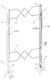
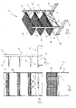
- Fig. 1 shows a frame system 2 for building up a shelf system 4 consisting of two columns 8 that are spaced apart by spacer elements 34.
- the columns 8 are constituted by open U-sections, the sides 10, 12 including cutouts 14 for inserting supports 16 for carrying displays 18, e.g. in the form of shelves, cf. Figs. 10 - 13.
- the columns 8 are constituted by open U-sections 35, the flanges 36, 38 of which constitute said sides 10, 12 of the columns 8.
- the spacer elements 34 are constituted by profiled flat iron bars that are welded together to a kind of decoration, and the ends of which being welded to the bottom 40 of the U-sectioned columns 8.
- the lower ends 20 of the columns 8 include cutouts 28 close to the flanges 36, 38 for receiving locking tongues 30, 32 in foot members 22, cf. also Fig. 7.
- the lower end of the column elements 8 furthermore includes a plate which is welded to the bottom 40 of the U-sections and to the flanges 36, 38, respectively.
- the said plate 48 includes a through-going tapped bushing 50 in which is placed an adjusting leg, which include a threaded rod 54 in the tapped bushing and interacting with the latter, the rod 54 including a bolt-shaped head 56 in the shown embodiment on which is provided a foot 58.
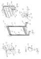
- Fig. 2 is a side view of a shelf 4 built up of a frame system made as the frame system shown in Fig. 1.
- the frame system is here provided with foot members 22.
- Fig. 3 is a top view of the shelf system shown in Fig. 2 including the frame system according to the invention from which appears that the frame elements 34 between the columns 8 are having a width which is less than the width of the bottom 40 of the U-sections 8 constituting the columns.
- the spacer elements 34 are placed at the centre of the bottom 40 of the U-sections, whereby slots 60 are formed between the flanges 36, 38 of the U-section and the facing sides of the spacer element 34, the slots 60 capable of being used for inserting a wing including print or colours.
- the wing can be constituted by a sheet item, e.g. a piece of corrugated cardboard, and the print can be constituted by advertisement text or pictures or other decoration.
- Fig. 4 is an end view of the shelf shown in Fig. 2 which is built up of the frame system 2 according to the invention.
- Fig. 5 is a perspective view of a shelf 4 built up of the frame system 2 shown in Fig. 1.
- the frame system is here provided with four foot members 22, and it further appears from Figs. 5A and 5B how the locking tongues 30, 32 are inserted in the slotted apertures 28 in the columns 8.
- the lower end of the columns 8 includes a plate 48 which is fastened to the bottom of the U-section 40 and to the flanges 36, 38 of the U-sections 8, and which plate includes a tapped bushing 50 in which adjusting legs 52 are inserted.
- Fig. 5C is a detail of the front end of a detail of a foot member 22 which is also provided with an adjusting leg 52, which is supported in an angular lug 92 on the foot member 22.
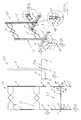
- Fig. 6 a perspective view of a shelf 4 built up of the frame system 2 shown in Fig. 1 during mounting of a foot member 22 at the lower end 20 of the column element 8.
- Fig. 7 which is a detail of the lower end 20 of the frame system 2, is shown how a foot member 22 is already inserted in the lower end 20 of the column element 8 by the locking tongues 30, 32 in the foot member 22 being arrested in slotted apertures 46 in the flanges 36, 38.
- Fig. 7 furthermore shows how a corresponding foot member 22 is on its way to insertion and arresting in the lower end 20 of the column element 8. This is effected by placing the foot member 22 with the locking tongues 30, 32 opposite to the slotted apertures 40 of the section 35, and then displacing the foot member with the tongues in front towards the bottom of the U-section, so that the locking tongues 30, 32 are inserted in the slots 42 as it appears from Fig. 8. After the locking tongues 30, 32 has been inserted in the slots 42, the lower side limitation 44 of the slotted apertures is brought into engagement in the slots 33 in the locking tongues 30, 32.
- FIGS. 10 - 13 are showing the frame system of Figs 2 - 5, provided with supports 16 and displays 18 in the form of shelves so that the practical application of the frame system 2 for building up a shelf system 4 is shown hereby.
- the supports can be designed in other ways, as well as the displays shown here may also be designed otherwise, and that the Figures 10 - 13 are only enclosed for the sake of completeness.
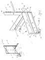
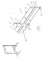
- Fig. 14 is shown a second embodiment of the frame system 2 according to the invention.
- the special feature of this embodiment is that the deflection strength of the columns is increased, as the U-shaped steel sections 35 constituting the columns 8 include a V-shaped profile bend 94 in the bottom 40 of the U-section running in the entire length of the column 8. This provides a significant stabilisation of the column against buckling at high loads.
- Figs. 14 - 16 is furthermore seen a second embodiment of the spacer elements 34 between the columns, which are here constituted by plate sections, the ends of which being fastened to the bottom 40 of the U-sections 35 at the area where the V-profiling 94 is located.
- the spacer elements 34 furthermore includes lugs 102, 104 for providing a not shown back plate that hereby may be disposed at the centre of the frame system.
- Fig. 17 is shown how an adjusting leg 52 is fastened at the lower end 20 of the columns 8. Space for the adjusting leg has been provided by establishing a cutout 106 in the V-shaped profiled bending 94.
- a locking pawl 98 constituted by a U-shaped section, the parallel lugs of which constitute tongues 98, 100 for reception in the slots 14 in flanges 10, 36, 12, 38 in the columns, as it appears from Fig. 14 and particularly from Fig. 15.
- the distance between the tongues 98, 100 corresponds to the distance between the slots 14 in the flanges 10, 36 or the flanges 12, 38 on the U-sections 35 of two columns that are disposed so that their respective bottoms 40 are in contact with each other.
- the locking pawl may thus be used for locking together a series of shelf sections 4 built up of the frame system according to the invention.
- the frame system there is thus indicated a very flexible element for building up shelf systems, e.g. for displaying goods, and which, also because of its open mode of construction, offers good possibility of establishing an efficient corrosion protection, meaning that the said shelf systems find application in humid environments and in environments with very great temperature variations.
- the open construction offers considerable savings in material
- the foot members 22 belonging to the frame system which are constituted by single layer profiled, pressed plates like the frame construction, offer very good possibility of establishing an efficient corrosion protection, e.g. by galvanising.
- the constructing of the foot members in combination with the frame system furthermore means that the foot members can be mounted in the frame system without using any tools, offering great flexibility of the shelf system 4 that may be built up of the frame system 2 and the foot members 22 associated therewith, respectively.
Landscapes
- Assembled Shelves (AREA)
Abstract
Description
- The present invention concerns a frame system for building up a shelf system, preferably for displaying articles in shops, department stores, supermarkets and warehouses, of the kind including columns standing up vertically from a base, at least one side of which, preferably two opposed sides, including cutouts running in parallel in longitudinal direction of the column for mounting supports projecting from these, between which displays are provided, e.g. in the shape of shelves, the columns being supported by at least one releasably attached foot member projecting from the lower end of the column and at the same side of the column from which the shelf supports are projecting, including adjustable legs, and where one end side of the foot member includes at least one projecting, first upper locking tongue interacting with cutouts in the column, and a second lower locking tongue, the downwards facing sides of which each including a slit.
- The above mentioned shelves are well-known and are used in many contexts in connection with particularly retail stores, where articles are placed on shelves disposed on the supports. The said shelf systems are typically constituted by columns with a closed column profile having a circular or rectangular cross-section. The shelf systems are typically delivered in assembly kits where column members and foot members are assembled at the site where the shelf system is to be used. It is of great importance that the said shelves are constituted by as few individual parts as possible, and furthermore that the said individual parts are readily assembled without using any special tools. Besides, it is required that the said shelf systems display statical stability, as it may be expected that the shelf systems are loaded even very heavily. Of further requirements to the said shelf systems can be mentioned that the weight of the these is to be as small as possible, and furthermore that the production costs in connection with their production are to be kept at an absolute minimum with regard to the very hard competition within the industry. So, at the same time very great demands are put on both the flexibility of the shelf systems and on requirement of a low price.
- The known shelf systems of the kind indicated including closed column profiles and partially closed foot members imply that providing an efficient corrosion protection of these metal parts made of steel or iron, e.g. by galvanising or similar, is even very difficult to accomplish within an acceptable cost level. The said limitations in possibilities to corrosion protect the said metal parts consequently imply limitations in the possibilities of use for the said shelves. Thus it will be less suitable to use the said shelf systems in e.g. cold stores and on locations where large variations in temperature and air humidity are to be expected, as the risk of corrosion in the metal parts (columns, foot members etc.) made of steel or iron will be great.
- From the description to US 3,747,777 (Kane) is known an adjustable storage rack including upright columns which are provided in mutual by means of sections. On the supports, carriers are provided. This shelf system is particularly suited for carrying long, heavy items, such as steel pipes. The upright columns are provided as U-shaped sections that are connected to a foot plate in such a way that the sections are provided with the bottoms against each other. Parts of the elements are adapted so that they may support the arms in relation to the upright columns, and so that connection may be achieved between the upright columns. By this shelf system is achieved a simple and cheap structure which is suited for mass production.
- From the description to US 3,601,346 is known a display device with a frame. This frame includes vertical stanchions and so-called base arms disposed horizontally therefrom and connected with the stanchion by means of hooks. The hooks are subjected to relatively strong compressive and tensile loads exerted by the weight placed on the base arms. The purpose of this construction is to provide a new and improved frame for display units, where one has particularly improved the base arms so that a lighter and more rigid construction, which is cheap to produce, is attained.
- From the description to US 3,570,798 is known a support for shelves, dress rails and the like, where there are cutouts in the supports in which hangers may be placed that consist of a first and a second member. The first member consists of a hook device that engages an opening and stop, and which limits rotatory movement in relation to the second element. The second element includes hooks which engage openings and stop which limit rotatory movement of the member towards the first member. Both members have through-going holes which are brought to lie opposite each other and are ensured mutual locking by a pin.
- It is the purpose of the invention to indicate a shelf system providing for demands for flexibility and acceptable price with regard to production costs combined with the shelves possibly finding application in localities with great variations in temperature as well as air humidity.
- Such a shelf system includes a frame system of the kind indicated in the introduction, which is characterised in that the frame system is built up of spaced columns that are constituted by uniform sections with an open, mainly U-shaped cross-section, the flanges of which being oriented towards each other, and the columns being interconnected by at least one rigid spacer element which is fastened in the bottom of the U-sections.
- Hereby is achieved a very stable frame system which is easily corrosion protected as a consequence of the column structure of open U-sections. Therefore, this design of the frame system may be made in steel or iron which is corrosion protected.
- Frame systems of the kind specified are typically loaded very heavily, as shop areas are utilised to the extreme. In some cases, it may be suitable to reinforce the deflecting stiffness of the columns made of U-sections. This reinforcement may conceivably be effected by an increase of the material thickness of the U-sections, which, however is not desirable. With the purpose of ensuring an increase of the deflection strength of the columns without increasing the material thickness of the U-sections, the bottom of the uniform sections making up the columns may have at least one profiling oriented in longitudinal directions of the column and to the same side as the flanges.
- Without abandoning other embodiments of the profiling of the U-shaped sections constituting the columns of the frame system according to the invention, it may be mentioned that in a preferred embodiment the profiling has a V-shaped cross-section.
- The said spacer elements that are fastened in the bottom of the U-sections can be fastened by bolts being passed through holes in the bottom of the U-sections and in flanges on the spacer elements, respectively, but in another embodiment they may also be fastened to the bottom of the U-sections by welding. The frame system is thus made up of frame systems which are provided with a suitable number of foot members, so that the erected frame systems which are to carry shelves, articles etc. are stable. A frame separation, e.g. in a shop, may be established by putting up a plurality of the frame systems in continuation of each other with the bottom of the U-sections facing each other, and where the said U-sections are clamped for the sake of stability, possibly by known bolt connections.
- With the purpose of enabling an easy and unencumbered mounting of the foot members on the columns, the frame system according to the invention may be designed so that cutouts in the columns for receiving the upper and the lower locking tongues, respectively, on a foot member are constituted by a slotted aperture in the bottom of the U-sections disposed close the flanges, the height of which at least corresponding to the height of the locking tongues, and that the lower side limitations of the slotted apertures communicate with a slot in the flanges of the U-sections, the slot having a height corresponding to the height of the slotted part of the locking tongues.
- By adapting the frame system as indicated above it is achieved that the foot members may be fitted at the lower end of the columns without using tools, as the foot members are mounted by inserting the locking tongues in the slotted aperture in the bottom of the U-sections, after which a 90° turning of the foot member is performed in this position, whereby the locking tongues are pivoted into the slotted apertures in the flanges of the U-sections, whereby the foot member is locked projecting in parallel with the bottom of the U-sections or perpendicularly to the flanges in the U-section.
- By performing a 90° pivoting of the foot member it is provided that the locking tongues are turned into the slotted apertures. The entire locking tongue is thereby supported and locked, and not only its projections or hook-shaped parts. Thus, the projection or the hook-shaped part may face downwards towards the base. The projection or hook-shaped part of the locking flaps is therefore not further loaded by the weight of the goods that are placed on the shelf system. Heavily loaded parts, particularly complex cross-sections in the locking lugs, may be difficult to produce accurately and to corrosion protect. If the complex cross-section is more lightly loaded, a stronger construction in relation to weight is achieved, and which is less influenced by temperature and humidity.
- With the purpose of achieving a stable installation of the frame system with associated, mounted feet on a base, the frame system according to the invention may at the same end of the column as the cutouts for the locking tongues include a plate fastened in the hollow of the U-section and to the flanges and bottom, respectively, of the U-section, including a tapped bushing for accommodating one end of an adjustable leg, including a threaded rod interacting with the tapped bushing, the opposite end of which including a head cooperating with a tool, the underside of the head including a foot.
- Hereby it will be possible to perform height adjustment of the support of the column.
- In connection with using the said frame system for racks or shelves, in connection with establishing shop fittings, it is often preferred to provide special back coverings including promotions or other kinds of illustrations, or just a wall element as partitioning on the frame system. By the known shelf systems, the said segments only allow substitution by actual disassembling of the frame system making up the basic substance of the shelf system, or by mounting special holding sections at the outer sides of the columns, and since this will be a relatively time-consuming work to perform, the said back walls are not replaced very often. The missing replacement naturally implies a stereotypical impression of the shelves in a shop fitting.
- The frame system according to the invention is a reassessment of this, since it can be designed so that the dimension of the spacer element between the flanges of the U-section can be less than the distance between the mutually facing sides of the flanges, and that the spacer element may furthermore be disposed between the flanges so that a slot appears between at least one of the sides of the spacer element and one of the flanges of the U-section.
- Hereby is achieved the advantage of enabling to insert e.g. a piece of cardboard or sheet segment between the flanges of the U-sections and the spacer element which is secured between the mutually facing sides of the parts. If the spacer element is further disposed relatively precisely at the centre of the bottom of the U-sections, it will thus be possible to insert a sheet-shaped object at each side of the shelf formed by the frame system, as the spacer element, together with the flanges, are forming a guideway in which the sheet-shaped may be inserted and secured. It will thus be possible to establish independent promotion/advertisement of the product placed on the shelves at each side of a shelf which is built up by means of the frame system according to the invention. The said facility thus opens for hitherto unseen possibilities for displaying articles on shop shelf systems.
- With regard to achieve a suitable modular structure of the frame system according to the invention, it may be noted that, without hereby abandoning the right to other embodiments, it is preferred that the rigid spacer element/s are fastened to the bottom of the U-sections by welding.
- The shelf system built up of the frame system according to the invention has a further characteristic, namely that the foot member is constituted by a profiled piece of plate with a mainly rectangular basic shape including a first upper and second lower continuous section extending in parallel, the facing sides of which being separated by an angle, and where the first upper section and the second lower section have a first, shorter side including the first and the second locking tongue and a second, shorter side including angular end lugs, respectively, and where the long sides facing away from each other and the first upper and the second, lower continuous, section extending in parallel, respectively, include a recess and an angular flange, respectively.
- Hence there is specified a foot member for a shelf system which is constituted by a single layer, profiled, pressed plate, which is rather remarkable in the light of the said foot members normally being constituted by a double layer section. The advantages of this consist, besides savings in material, which is also achieved in connection with the U-shaped column sections. A further advantage by the single plate section used for the foot members is that an efficient corrosion protection, e.g. by galvanising said plate parts constituting the foot members, will be even easy to perform. All things considered this means that it will be possible to use a shelf system constructed by the frame system and the foot members in galvanised form according to the invention, e.g. in cold stores and in other localities with strongly varying air humidity and temperatures.
- With the purpose of performing adjustment of the height of the foot members and the base for stabilising the shelf system built up of the frame system and the foot members, close to the end including the angular end lugs the angular flange includes a tapped bushing for receiving one end of an adjustable leg, including a threaded rod interacting with the tapped bushing, the opposite end of which rod including a head interacting with a tool, the underside of which head including a foot. Hereby is established an adjusting leg at the free end of the foot plate which, combined with the adjusting leg on the columns, is usable for adjusting a shelf built up of the frame system according to the invention.
- In connection with using shelves in shops, the case is frequently that the shelves are placed in continuation of each other for achieving division of the shop area, whereby passages are formed on which customers are moving between the entrance and the check-out area at the exit. In these cases, the shelves are placed so that the columns in the frames of which the shelf system is built up of, are in contact with each other, i.e. the bottoms of the U-sections in two mutually facing columns are in mutual contact. With the purpose of keeping the said shelf systems in this position, as accessory there may be used a locking pawl for mutual arresting of to succeeding frame sections, the U-shaped locking pawl including uniform lugs extending in parallel for accommodation in the slots on two succeeding, adjacent columns, the bottoms of which are facing each other.
- By the invention is thus indicated a very flexible shelf system with a hitherto unseen open construction which additionally may be assembled without the use of tools, and which also allow establishing of a very efficient corrosion protection of the parts that form part of the frame system and the foot members making up the basic substance of the shelf system. By the open structure there is furthermore achieved a significant material saving contributing to the shelf system according to the invention to be produced at lower cost that the cost of producing the prior art shelf systems of the kind indicated.
- The invention is explained in more detail in the following with reference to the drawing, where:
- Fig. 1
- is a perspective view of the frame system for a shelf or rack according to the invention;
- Fig. 2
- is a front view of a shelf built up of the frame system according to the invention;
- Fig. 3
- is a top view of the shelf shown in Fig. 2;
- Fig. 4
- is an end view of the shelf shown in Fig. 2;
- Fig. 5
- is a perspective view of the shelf shown in Fig. 2 seen obliquely from above;
- Fig. 5A
- is a detailed view of an assembly of foot members and columns in the frame system;
- Fig. 5B
- shows the same as Fig. 5A, seen from the opposite side of the U-sectioned column;
- Fig. 5C
- is a detailed view of the upper end of a foot member including an adjusting leg;
- Fig. 6
- is a perspective view of a shelf section built up of the frame system above the foot member according to the invention, during mounting of a foot member;
- Fig. 7
- is a detail of the lower end of a column of the frame system according to the invention while inserting a foot member in slots in the columns interacting with the foot member;
- Fig. 8
- shows the foot member inserted in the column;
- Fig. 9
- shows the foot member pivoted into position, projecting perpendicularly from the flanges of the U-sectioned columns;
- Fig. 10
- shows the shelf system of Fig. 2 provided with displays;
- Fig. 11
- is a top view of Fig. 10
- Fig. 12
- is a side view of the same;
- Fig. 13
- is a perspective view of the shelf shown in Fig. 10;
- Fig. 14
- is a perspective view of a second embodiment of the frame system for building up a shelf according to the invention;
- Fig. 15
- is a perspective view of a detail of the upper end of the frame system shown in Fig. 14, as seen from the outer side;
- Fig. 16
- is a perspective view of a detail of the upper end of the frame system shown in Fig. 14, as seen from the inner side;
- Fig. 17
- is a perspective view of a detail of the lower end of the frame system shown in Fig. 14, as seen from the inner side, and
- Fig. 18
- is a perspective view of a locking pawl for a shelf system, built up of the frame system according to the invention.
- Fig. 1 shows a
frame system 2 for building up a shelf system 4 consisting of twocolumns 8 that are spaced apart byspacer elements 34. As it appears, thecolumns 8 are constituted by open U-sections, the sides 10, 12 includingcutouts 14 for insertingsupports 16 for carryingdisplays 18, e.g. in the form of shelves, cf. Figs. 10 - 13. As it appears, thecolumns 8 are constituted by open U-sections 35, theflanges columns 8. - In the shown embodiment, the
spacer elements 34 are constituted by profiled flat iron bars that are welded together to a kind of decoration, and the ends of which being welded to the bottom 40 of theU-sectioned columns 8. As it further appears from Fig. 1, the lower ends 20 of thecolumns 8 includecutouts 28 close to theflanges tongues foot members 22, cf. also Fig. 7. The lower end of thecolumn elements 8 furthermore includes a plate which is welded to the bottom 40 of the U-sections and to theflanges plate 48 includes a through-going tappedbushing 50 in which is placed an adjusting leg, which include a threaded rod 54 in the tapped bushing and interacting with the latter, the rod 54 including a bolt-shapedhead 56 in the shown embodiment on which is provided a foot 58. - Fig. 2 is a side view of a shelf 4 built up of a frame system made as the frame system shown in Fig. 1. The frame system is here provided with
foot members 22. Fig. 3 is a top view of the shelf system shown in Fig. 2 including the frame system according to the invention from which appears that theframe elements 34 between thecolumns 8 are having a width which is less than the width of the bottom 40 of theU-sections 8 constituting the columns. As it furthermore appears, thespacer elements 34 are placed at the centre of the bottom 40 of the U-sections, wherebyslots 60 are formed between theflanges spacer element 34, theslots 60 capable of being used for inserting a wing including print or colours. The wing can be constituted by a sheet item, e.g. a piece of corrugated cardboard, and the print can be constituted by advertisement text or pictures or other decoration. - Fig. 4 is an end view of the shelf shown in Fig. 2 which is built up of the
frame system 2 according to the invention. - Fig. 5 is a perspective view of a shelf 4 built up of the
frame system 2 shown in Fig. 1. As it appears, the frame system is here provided with fourfoot members 22, and it further appears from Figs. 5A and 5B how the lockingtongues apertures 28 in thecolumns 8. Furthermore, it particularly appears from Fig. 5B how the lower end of thecolumns 8 includes aplate 48 which is fastened to the bottom of the U-section 40 and to theflanges U-sections 8, and which plate includes a tappedbushing 50 in which adjustinglegs 52 are inserted. Fig. 5C is a detail of the front end of a detail of afoot member 22 which is also provided with an adjustingleg 52, which is supported in anangular lug 92 on thefoot member 22. - In the Figures 6 - 9 is shown how the
foot member 22 is mounted and fastened to acolumn element 8 which will be described in the following. - In Fig. 6 is shown a perspective view of a shelf 4 built up of the
frame system 2 shown in Fig. 1 during mounting of afoot member 22 at thelower end 20 of thecolumn element 8. - In Fig. 7, which is a detail of the
lower end 20 of theframe system 2, is shown how afoot member 22 is already inserted in thelower end 20 of thecolumn element 8 by the lockingtongues foot member 22 being arrested in slottedapertures 46 in theflanges corresponding foot member 22 is on its way to insertion and arresting in thelower end 20 of thecolumn element 8. This is effected by placing thefoot member 22 with the lockingtongues apertures 40 of thesection 35, and then displacing the foot member with the tongues in front towards the bottom of the U-section, so that the lockingtongues slots 42 as it appears from Fig. 8. After the lockingtongues slots 42, thelower side limitation 44 of the slotted apertures is brought into engagement in theslots 33 in the lockingtongues - After the locking
tongues slots 42 in the bottom 42 of the U-section 35 constituting thecolumn elements 8, a turning of thefoot member 22 in direction of the arrow B is performed, so that the foot member is oriented in parallel with the bottom 40 of theU-shaped section 35 constituting thecolumn 8 as shown in Fig. 9. By this turning, the locking tongues are pivoted for arresting in the slottedapertures 46 in theflange 36 whereby the foot member is arrested. This is possible as consequence of the slottedaperture 46 in theflanges slot 33, i.e. a part of theflange 36 is accommodated in theslot 33 in the foot member whereby the foot member will be able to absorb moment forces coming fromsupports 16 withdisplays 18, e.g. in the form of shelves etc. - The Figures 10 - 13 are showing the frame system of Figs 2 - 5, provided with
supports 16 and displays 18 in the form of shelves so that the practical application of theframe system 2 for building up a shelf system 4 is shown hereby. Finally, it is to be mentioned that the supports can be designed in other ways, as well as the displays shown here may also be designed otherwise, and that the Figures 10 - 13 are only enclosed for the sake of completeness. - In Fig. 14 is shown a second embodiment of the
frame system 2 according to the invention. The special feature of this embodiment is that the deflection strength of the columns is increased, as theU-shaped steel sections 35 constituting thecolumns 8 include a V-shapedprofile bend 94 in the bottom 40 of the U-section running in the entire length of thecolumn 8. This provides a significant stabilisation of the column against buckling at high loads. In Figs. 14 - 16 is furthermore seen a second embodiment of thespacer elements 34 between the columns, which are here constituted by plate sections, the ends of which being fastened to the bottom 40 of the U-sections 35 at the area where the V-profiling 94 is located. Thespacer elements 34 furthermore includeslugs - In Fig. 17 is shown how an adjusting
leg 52 is fastened at thelower end 20 of thecolumns 8. Space for the adjusting leg has been provided by establishing acutout 106 in the V-shaped profiled bending 94. - In Fig. 18 is shown a locking
pawl 98 constituted by a U-shaped section, the parallel lugs of which constitutetongues slots 14 inflanges tongues slots 14 in theflanges 10, 36 or theflanges 12, 38 on theU-sections 35 of two columns that are disposed so that theirrespective bottoms 40 are in contact with each other. The locking pawl may thus be used for locking together a series of shelf sections 4 built up of the frame system according to the invention. - By the frame system there is thus indicated a very flexible element for building up shelf systems, e.g. for displaying goods, and which, also because of its open mode of construction, offers good possibility of establishing an efficient corrosion protection, meaning that the said shelf systems find application in humid environments and in environments with very great temperature variations. Furthermore, the open construction offers considerable savings in material, and the
foot members 22 belonging to the frame system, which are constituted by single layer profiled, pressed plates like the frame construction, offer very good possibility of establishing an efficient corrosion protection, e.g. by galvanising. The constructing of the foot members in combination with the frame system furthermore means that the foot members can be mounted in the frame system without using any tools, offering great flexibility of the shelf system 4 that may be built up of theframe system 2 and thefoot members 22 associated therewith, respectively. -
- 2
- frame system
- 4
- shelf system
- 6
- base
- 8
- columns
- 10
- side of column
- 12
- side of column
- 14
- first cutout in side 10, 12 for supports
- 16
- supports
- 18
- displays, e.g. shelves etc.
- 20
- lower end of columns
- 22
- foot members
- 24
- adjustable legs on 22
- 26
- one end side of
foot member 22 - 28
- cutout in column for foot members
- 30
- first upper locking tongue on foot member
- 32
- second lower locking tongues on foot member
- 33
- slot on downwards facing sides of 30, 32
- 34
- spacer element between
columns 8 - 35
-
U-section constituting columns 8 - 36
- flange of column
- 38
- flange of column
- 40
- bottom of U-section
- 42
- slotted aperture
- 44
- lower side limitation of
slot 42 - 46
- slotted aperture in
flanges - 48
- plate in
U-shaped section 50 - 50
- tapped bushing
- 52
- adjustable leg
- 54
- threaded rod
- 56
- bolt-shaped head
- 58
- foot
- 60
- slot between spacer element and flange on U-section
- 62
- profiled plate section constituting 22
- 64
- first section of 62
- 66
- second section of 62
- 68
- side of 64 facing 66
- 70
- side of 66 facing 64
- 72
- angular bend
- 74
- first short side of 64
- 76
- first short side of 66
- 78
- second short side of 64
- 80
- second short side of 66
- 82
- angular end lug on 78
- 84
- angular end lug on 80
- 86
- long side of 64 facing away from 66
- 88
- long side of 66 facing away from 64
- 90
- recess
- 92
- angular lug
- 94
- profiling at bottom of U-section
- 96
- U-shaped locking pawl
- 98
- tongue on lug on
U-shaped locking pawl 96 - 100
- tongue on lug on U-shape locking pawl
- 102
- lug on
spacer element 34 - 104
- lug on
spacer element 34 - 106
- cutout in
bottom 40 of U-section 35 in 94
Claims (10)
- Frame system (2) for building a shelf system (4), preferably for displaying articles in shops, department stores, supermarkets and warehouses, of the kind including columns (8) standing up vertically from a base (6), at least one side (10) of which, preferably two opposed sides (10, 12), including cutouts (14) running in parallel in longitudinal direction of the column for mounting supports (16) projecting from these, between which displays are provided, e.g. in the shape of shelves (18), the columns (8) being supported by at least one releasably attached foot member (22) projecting from the lower end (20) of the column and at the same side of the column from which the shelf supports are projecting, including adjustable legs, and where one end side of the foot member includes at least one projecting, first upper locking tongue (30) interacting with cutouts (28) in the column, and a second lower locking tongue (32), the downwards facing sides of which each including a slit (33), characterised in that the frame system (2) is built up of spaced columns (8) that are constituted by uniform sections with an open, mainly U-shaped cross-section, the flanges (36, 38) of which being oriented towards each other, and the columns (8) being interconnected by at least one rigid spacer element (34) which is fastened in the bottom (40) of the U-sections.
- Frame system according to claim 1, characterised in that the bottom (40) of the uniform sections constituting the columns (8) have at least one profiling (94) oriented in the longitudinal direction of the columns and to the same side as the flanges (36, 38).
- Frame system according to claim 2, characterised in that the profiling (94) has a V-shaped cross-section.
- Frame system (2) according to any of claims 1 to 3, characterised in that the cutouts (28) in the columns (8) for receiving the upper and the lower locking tongues (30, 32), respectively, on a foot member (22) are constituted by a slotted aperture (42) in the bottom (40) of the U-sections (8) disposed close the flanges (36,38), the height of which at least corresponding to the height of the locking tongues (30, 32), and that the lower side limitations (44) of the slotted apertures communicate with a slot (46) in the flanges (36, 38) of the U-sections, the slot (46) having a height corresponding to the height of the slotted part of the locking tongues (30,32).
- Frame system according to any of claims 1 - 4, characterised in that the U-sections (8) at least at one end, preferably at the same end of the column (8) as the cutouts (28) for the locking tongues (30, 32), include a plate (48) fastened in the hollow of the U-section and to the flanges (36, 38) and bottom (40), respectively, of the U-section, including a tapped bushing (50) for accommodating one end of an adjustable leg (52), including a threaded rod (54) interacting with the tapped bushing (50), the opposite end of which including a head (56) cooperating with a tool, the underside of the head including a foot (58).
- Frame system according to any of claims 1 - 5, characterised in that the dimension of the spacer element (34) between the flanges (36, 38) of the U-section is less than the distance between the mutually facing sides of the flanges (36,38), and that the spacer element (34) is disposed between the flanges (36, 38) so that a slot (60) appears between one of the sides of the spacer element (34) and one of the flanges (36, 38) of the U-section.
- Frame system according to any of claims 1 - 6, characterised in that the rigid spacer element (34) is secured to the bottom (40) of the U-sections by welding.
- Shelf system (4) built up of the frame system according to any of claims 1 - 7, characterised in that the foot members (22) are constituted by a profiled plate member (62) having a mainly rectangular basic shape, including a first upper and a second lower continuous section (64, 65) extending in parallel, the facing sides (68, 70) of which being separated by an angle (72), and where the first upper section (64) and the second lower section (66) have a first, shorter side including the first and the second locking tongue (30, 32) and a second, shorter side (78, 80 including angular end lugs (82, 84), respectively, and where the long sides (86, 88) facing away from each other and the first upper and the second, lower continuous, section (64, 66) extending in parallel, respectively, include a recess (90) and an angular flange (92), respectively.
- Shelf system according to claim 8, characterised in that close to the end (78, 80) including the angular end lugs (82, 84), the angular flange (92) includes a tapped bushing (50) for receiving one end of an adjustable leg (52), including a threaded rod (54) interacting with the tapped bushing (50), the opposite end of which rod including a head (56) interacting with a tool, the underside of which head including a foot (58).
- Shelf system according to claim 8 or 9, characterised in that this includes a U-shaped locking pawl (96) for mutual arresting of to succeeding frame sections, the U-shaped locking pawl (96) including uniform lugs (98, 100) extending in parallel for accommodation in the slots (14) on two succeeding, adjacent columns (8), the bottoms (40) of which are facing each other.
Applications Claiming Priority (2)
| Application Number | Priority Date | Filing Date | Title |
|---|---|---|---|
| DK200300161A DK175782B1 (en) | 2003-02-05 | 2003-02-05 | Frame system for building a shelving system, as well as shelving system built by the frame system |
| DK200300161 | 2003-02-05 |
Publications (1)
| Publication Number | Publication Date |
|---|---|
| EP1444923A1 true EP1444923A1 (en) | 2004-08-11 |
Family
ID=32605198
Family Applications (1)
| Application Number | Title | Priority Date | Filing Date |
|---|---|---|---|
| EP04002208A Withdrawn EP1444923A1 (en) | 2003-02-05 | 2004-02-02 | Frame system for building a shelf system |
Country Status (2)
| Country | Link |
|---|---|
| EP (1) | EP1444923A1 (en) |
| DK (1) | DK175782B1 (en) |
Cited By (2)
| Publication number | Priority date | Publication date | Assignee | Title |
|---|---|---|---|---|
| WO2008060221A3 (en) * | 2006-11-16 | 2009-07-30 | Elfa Int Ab | Self-supporting suspension device and method for assembling thereof |
| DE102009022132A1 (en) * | 2009-05-20 | 2010-11-25 | Vendox Gmbh | shelving |
Citations (5)
| Publication number | Priority date | Publication date | Assignee | Title |
|---|---|---|---|---|
| DE3028552A1 (en) * | 1980-07-28 | 1982-02-25 | Tegometall Rudolf Bohnacker, 7482 Krauchenwies | Angled support unit for shelves - has inner pressure distribution member ensuring even load bearing and overall stability |
| US5433327A (en) * | 1993-07-26 | 1995-07-18 | Knape & Vogt Canada, Inc. | Merchandise display rack with reinforced bases |
| WO1996010936A1 (en) * | 1994-10-07 | 1996-04-18 | Goeranson Per | Arrangement at uprights for the carrying of cantilever brackets for shelves |
| GB2325398A (en) * | 1997-05-20 | 1998-11-25 | Bekaert Handling & Display Ltd | Support foot for display shelving |
| EP0947151A2 (en) * | 1998-04-01 | 1999-10-06 | Meta- Regalbau Gmbh | Shelf unit |
-
2003
- 2003-02-05 DK DK200300161A patent/DK175782B1/en not_active IP Right Cessation
-
2004
- 2004-02-02 EP EP04002208A patent/EP1444923A1/en not_active Withdrawn
Patent Citations (5)
| Publication number | Priority date | Publication date | Assignee | Title |
|---|---|---|---|---|
| DE3028552A1 (en) * | 1980-07-28 | 1982-02-25 | Tegometall Rudolf Bohnacker, 7482 Krauchenwies | Angled support unit for shelves - has inner pressure distribution member ensuring even load bearing and overall stability |
| US5433327A (en) * | 1993-07-26 | 1995-07-18 | Knape & Vogt Canada, Inc. | Merchandise display rack with reinforced bases |
| WO1996010936A1 (en) * | 1994-10-07 | 1996-04-18 | Goeranson Per | Arrangement at uprights for the carrying of cantilever brackets for shelves |
| GB2325398A (en) * | 1997-05-20 | 1998-11-25 | Bekaert Handling & Display Ltd | Support foot for display shelving |
| EP0947151A2 (en) * | 1998-04-01 | 1999-10-06 | Meta- Regalbau Gmbh | Shelf unit |
Cited By (3)
| Publication number | Priority date | Publication date | Assignee | Title |
|---|---|---|---|---|
| WO2008060221A3 (en) * | 2006-11-16 | 2009-07-30 | Elfa Int Ab | Self-supporting suspension device and method for assembling thereof |
| RU2419369C2 (en) * | 2006-11-16 | 2011-05-27 | Эльфа Интернэшнл Аб | Self-supported suspended device and method of its assembly |
| DE102009022132A1 (en) * | 2009-05-20 | 2010-11-25 | Vendox Gmbh | shelving |
Also Published As
| Publication number | Publication date |
|---|---|
| DK200300161A (en) | 2004-08-06 |
| DK175782B1 (en) | 2005-02-21 |
Similar Documents
| Publication | Publication Date | Title |
|---|---|---|
| US10555604B2 (en) | Cantilever shelving system | |
| US8443992B2 (en) | Industrial frame rack support assembly | |
| US5482168A (en) | Modular wall-mounted storage system | |
| US6978906B2 (en) | Modular rack conversion apparatus and method | |
| US9883755B2 (en) | Shelving system | |
| US4186666A (en) | Wall unit | |
| CA1334084C (en) | Modular shelving and hanger bar system | |
| US20050199569A1 (en) | M-divider material-bay restraining cable system | |
| US5553551A (en) | Interlocking modular bench system | |
| US5072839A (en) | Display stand assembly | |
| WO1996016579A1 (en) | A modular tiered rack assembly | |
| CN113939213B (en) | Industrial frame | |
| NL8320397A (en) | METHOD FOR BUILDING A BEARING PANEL WALL AND A PROFILE PART FOR USE IN THE METHOD | |
| US20030094124A1 (en) | Modular pallet display system | |
| EP1444923A1 (en) | Frame system for building a shelf system | |
| US20050167383A1 (en) | Merchandise display rack | |
| CZ297567B6 (en) | Shelf | |
| EP0005901B1 (en) | Wall unit for use in the storage and/or display of articles, and structure incorporating such a unit | |
| US20240023707A1 (en) | Cantilever rack | |
| US7322483B2 (en) | Cantilever shelving for utility shed | |
| JP3860946B2 (en) | Store fixtures | |
| JP7560033B2 (en) | Shelf mounting device | |
| JP3004620U (en) | Display device for long objects | |
| KR960006612B1 (en) | Shelf arrangement | |
| PL197991B1 (en) | Cross-member of a shelved rack structure |
Legal Events
| Date | Code | Title | Description |
|---|---|---|---|
| PUAI | Public reference made under article 153(3) epc to a published international application that has entered the european phase |
Free format text: ORIGINAL CODE: 0009012 |
|
| AK | Designated contracting states |
Kind code of ref document: A1 Designated state(s): AT BE BG CH CY CZ DE DK EE ES FI FR GB GR HU IE IT LI LU MC NL PT RO SE SI SK TR |
|
| AX | Request for extension of the european patent |
Extension state: AL LT LV MK |
|
| 17P | Request for examination filed |
Effective date: 20040925 |
|
| AKX | Designation fees paid |
Designated state(s): AT BE BG CH CY CZ DE DK EE ES FI FR GB GR HU IE IT LI LU MC NL PT RO SE SI SK TR |
|
| 17Q | First examination report despatched |
Effective date: 20060921 |
|
| STAA | Information on the status of an ep patent application or granted ep patent |
Free format text: STATUS: THE APPLICATION IS DEEMED TO BE WITHDRAWN |
|
| 18D | Application deemed to be withdrawn |
Effective date: 20070403 |