EP1444105B1 - Self-contained radio apparatus for transmission of data - Google Patents
Self-contained radio apparatus for transmission of data Download PDFInfo
- Publication number
- EP1444105B1 EP1444105B1 EP02779674A EP02779674A EP1444105B1 EP 1444105 B1 EP1444105 B1 EP 1444105B1 EP 02779674 A EP02779674 A EP 02779674A EP 02779674 A EP02779674 A EP 02779674A EP 1444105 B1 EP1444105 B1 EP 1444105B1
- Authority
- EP
- European Patent Office
- Prior art keywords
- patch
- antenna
- post
- radio apparatus
- radio
- Prior art date
- Legal status (The legal status is an assumption and is not a legal conclusion. Google has not performed a legal analysis and makes no representation as to the accuracy of the status listed.)
- Expired - Lifetime
Links
- 230000005540 biological transmission Effects 0.000 title claims description 6
- 239000000463 material Substances 0.000 claims description 9
- 239000000853 adhesive Substances 0.000 claims description 5
- 230000001070 adhesive effect Effects 0.000 claims description 5
- 229920002379 silicone rubber Polymers 0.000 claims description 3
- 239000004945 silicone rubber Substances 0.000 claims description 3
- 239000004020 conductor Substances 0.000 claims 1
- 238000004519 manufacturing process Methods 0.000 description 4
- 238000000034 method Methods 0.000 description 4
- 235000001674 Agaricus brunnescens Nutrition 0.000 description 2
- 230000001154 acute effect Effects 0.000 description 1
- 230000000712 assembly Effects 0.000 description 1
- 238000000429 assembly Methods 0.000 description 1
- 238000004891 communication Methods 0.000 description 1
- 230000000694 effects Effects 0.000 description 1
- 238000005516 engineering process Methods 0.000 description 1
- -1 for example Substances 0.000 description 1
- 238000000465 moulding Methods 0.000 description 1
- 238000010897 surface acoustic wave method Methods 0.000 description 1
- 210000000707 wrist Anatomy 0.000 description 1
Images

Classifications
-
- H—ELECTRICITY
- H01—ELECTRIC ELEMENTS
- H01Q—ANTENNAS, i.e. RADIO AERIALS
- H01Q1/00—Details of, or arrangements associated with, antennas
- H01Q1/12—Supports; Mounting means
- H01Q1/22—Supports; Mounting means by structural association with other equipment or articles
- H01Q1/2208—Supports; Mounting means by structural association with other equipment or articles associated with components used in interrogation type services, i.e. in systems for information exchange between an interrogator/reader and a tag/transponder, e.g. in Radio Frequency Identification [RFID] systems
- H01Q1/2241—Supports; Mounting means by structural association with other equipment or articles associated with components used in interrogation type services, i.e. in systems for information exchange between an interrogator/reader and a tag/transponder, e.g. in Radio Frequency Identification [RFID] systems used in or for vehicle tyres
-
- B—PERFORMING OPERATIONS; TRANSPORTING
- B60—VEHICLES IN GENERAL
- B60C—VEHICLE TYRES; TYRE INFLATION; TYRE CHANGING; CONNECTING VALVES TO INFLATABLE ELASTIC BODIES IN GENERAL; DEVICES OR ARRANGEMENTS RELATED TO TYRES
- B60C23/00—Devices for measuring, signalling, controlling, or distributing tyre pressure or temperature, specially adapted for mounting on vehicles; Arrangement of tyre inflating devices on vehicles, e.g. of pumps or of tanks; Tyre cooling arrangements
- B60C23/02—Signalling devices actuated by tyre pressure
- B60C23/04—Signalling devices actuated by tyre pressure mounted on the wheel or tyre
- B60C23/0408—Signalling devices actuated by tyre pressure mounted on the wheel or tyre transmitting the signals by non-mechanical means from the wheel or tyre to a vehicle body mounted receiver
- B60C23/0422—Signalling devices actuated by tyre pressure mounted on the wheel or tyre transmitting the signals by non-mechanical means from the wheel or tyre to a vehicle body mounted receiver characterised by the type of signal transmission means
- B60C23/0433—Radio signals
-
- B—PERFORMING OPERATIONS; TRANSPORTING
- B60—VEHICLES IN GENERAL
- B60C—VEHICLE TYRES; TYRE INFLATION; TYRE CHANGING; CONNECTING VALVES TO INFLATABLE ELASTIC BODIES IN GENERAL; DEVICES OR ARRANGEMENTS RELATED TO TYRES
- B60C23/00—Devices for measuring, signalling, controlling, or distributing tyre pressure or temperature, specially adapted for mounting on vehicles; Arrangement of tyre inflating devices on vehicles, e.g. of pumps or of tanks; Tyre cooling arrangements
- B60C23/02—Signalling devices actuated by tyre pressure
- B60C23/04—Signalling devices actuated by tyre pressure mounted on the wheel or tyre
- B60C23/0491—Constructional details of means for attaching the control device
- B60C23/0493—Constructional details of means for attaching the control device for attachment on the tyre
Definitions
- This invention relates to radio apparatus, and more particularly to self-contained radio apparatus for transmission of data.
- radio apparatus is used for transmitting data.
- the radio apparatus used comprises two elements, firstly a radio device which is the source of the data to be transmitted, and secondly one or more antennae used for communication with the radio device. Whilst combinations of antennae and radio device can readily be produced under laboratory conditions for testing purposes, implementation of antennae and radio device combinations in relatively hostile environments presents substantial practical difficulties.
- a self contained radio apparatus according to the preamble of claim 1 is known from EP 1048 494.
- a radio device may be used, for example, to generate radio signals indicative of the temperature or pressure within a vehicle tyre or to provide information as to the history of usage of the tyre
- the environment of a vehicle tyre presents a number of difficulties in the implementation of radio technology to communicate with the radio device.
- the antenna required will, in general, be flexible and will be several tens of centimetres in length.
- the sensor package will be rigid and very small - typically less than 10mm square and less than 5mm thick. Because of the size of the antenna it must, as a practical matter, be secured to or embedded in the material of the tyre. This material is subject to significant flexing as the wheel carrying the tyre rotates. This repeated flexing makes it very difficult to provide reliable connections between the antenna and the relatively small rigid package.
- the present invention avoids the problem outlined above by providing self-contained radio apparatus for the transmission of data according to claim 1.
- a post which is upstanding from one major surface of the patch provides a mounting means at the end thereof remote from the patch which is substantially de-coupled from the mechanical strain to which the patch may be subject in use. Essentially, even if the strain imposed on the patch is transmitted to the base of the post, very little of such strain will be transmitted to the end of the post remote from the patch.
- the patch is adhesively secured on the major surface thereof opposite to that from which the post extends to the inside of a tyre.
- the patch will readily conform to the interior surface of the tyre and can be adhesively bonded thereto using conventional adhesive techniques.
- the radio device may be secured to the post after the patch has been secured to the tyre or, in the preferred embodiment, during manufacture of the apparatus.
- a complete radio apparatus comprising antenna and radio device is assembled with the patch and post during manufacture to produce a complete unit which can readily be retro-fitted to an existing tyre by means of conventional adhesive techniques.
- the ability to provide the complete radio apparatus as a pre-formed assembly which can easily be secured in position using unskilled labour is a substantial practical advantage of the invention.
- the illustrated apparatus 1 comprises a zig-zag dipole antenna 2 which is moulded into a patch 3 of suitable resilient deformable material, for example a silicone rubber.
- the antenna 2 is formed of a suitably deformable material, for example, a flexible wire braid. The combination of this material and the shape of the antenna means that as the patch 3 is strained the dipole antenna is able to deform without difficulty.
- a post 4 Formed integrally with the patch 3, and of the same material as the patch 3, is a post 4 which extends upwardly from one major face 5 of the patch.
- the length of the posts, measured from the surface of the patch 3, is such that the end 6 of the post remote from the patch 3 will be substantially decoupled from all mechanical strain to which the patch 3 is subject in use:
- the end 6 of the post 4 provides a mounting for a package comprising a sensor or other data source, together with means, for example surface acoustic wave devices, to generate appropriate radio signals for transmission by the antenna 2.
- Wires 7 provide pins which project from the post 4 for connection to the package. The wires 7 are connected to the antenna 2.
- the apparatus described is secured, for example by adhesive, to the inside surface 8 of a vehicle tyre 9.
- the area to which the patch is secured exhibits substantial repeated deformation. Because of the resiliently flexible nature of the patch 3 and the deformable nature of the antenna 2, this deformation can readily be accommodated.
- the package which is mounted atop the post 4 is substantially decoupled from the strain to which the patch is subject and accordingly robust electrical connections to the wires 7 can readily be provided.
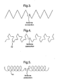
- Figures 3,4 and 5 show various proposals for the antenna 2.
- the zig-zag arrangement illustrated in Figure 1 is shown in more detail in Figure 3.
- an antenna form 10 is shown comprising a repeating pattern of straight portions interconnected by alternate acute and obtuse angle bends.
- a coil antenna 11 is shown.
- the turns of the antenna in Figure 5 are collapsed on top of each other.
- the wire from which the antenna is made is insulated or care is taken to provide an insulating layer between the collapsed turns of the coil.
- the patch 3 and antenna 2 are substantially as described above with reference to Figure 1.
- the post consists of a shaft 12 and a mushroom head 13.
- the patch 3, shaft 12 and mushroom head 13 are formed as an integral moulding of suitable material, for example, silicone rubber.
- suitable material for example, silicone rubber.
- a radio package 15 comprising a sensor is secured to the surface 14 and is connected by wires 16 to the antenna.
- the invention has particular utility in the context of tyre mounted devices, the invention is not limited to such applications. Indeed, although the invention has been designed primarily with a view to accommodating repeated strain within the antenna zone, the invention may be used in applications where no substantial strain occurs.
- the flexible nature of the patch makes the device ideal to be secured to either flat or curved surfaces.
- the ability of the invention to be pre-formed as a complete unit comprising antenna and radio package under optimum assembly conditions, and then to apply the package in its use position under general manufacturing or site conditions offers a very substantial advantage. Effectively, complete apparatus can be manufactured and tested under well controlled conditions appropriate to the assembly of electronic equipment.
- the complete unit once manufactured and tested can be deployed either to an alternative manufacturing plant (for example a tyre factory) to be secured to another device by simple assembly techniques which may be performed by unskilled or semi-skilled operatives.
- an alternative manufacturing plant for example a tyre factory
- the highly flexible nature of the patch means that the complete assembly can be applied under circumstances where conventional relatively rigid assemblies would not be suitable.
- the patch could be formed into a wrist band to form an identity device for wear by a human or animal.
- the patch may provide a means of mounting the entire device on the exterior surface of shafts and pipes by means of simple adhesive or mechanical fast techniques.
Landscapes
- Engineering & Computer Science (AREA)
- Mechanical Engineering (AREA)
- Arrangements For Transmission Of Measured Signals (AREA)
- Support Of Aerials (AREA)
- Details Of Aerials (AREA)
- Measuring Fluid Pressure (AREA)
Description
- This invention relates to radio apparatus, and more particularly to self-contained radio apparatus for transmission of data.
- Our prior United Kingdom patent application GB-A-2361546 proposes various arrangements whereby radio apparatus is used for transmitting data. The radio apparatus used comprises two elements, firstly a radio device which is the source of the data to be transmitted, and secondly one or more antennae used for communication with the radio device. Whilst combinations of antennae and radio device can readily be produced under laboratory conditions for testing purposes, implementation of antennae and radio device combinations in relatively hostile environments presents substantial practical difficulties.
- A self contained radio apparatus according to the preamble of
claim 1 is known from EP 1048 494. - One environment which gives rise to particular problems is that of vehicle tyres. Although a radio device may be used, for example, to generate radio signals indicative of the temperature or pressure within a vehicle tyre or to provide information as to the history of usage of the tyre, the environment of a vehicle tyre presents a number of difficulties in the implementation of radio technology to communicate with the radio device. In particular, at the frequencies typically used for this type of radio device the antenna required will, in general, be flexible and will be several tens of centimetres in length. In contrast, the sensor package will be rigid and very small - typically less than 10mm square and less than 5mm thick. Because of the size of the antenna it must, as a practical matter, be secured to or embedded in the material of the tyre. This material is subject to significant flexing as the wheel carrying the tyre rotates. This repeated flexing makes it very difficult to provide reliable connections between the antenna and the relatively small rigid package.
- The present invention avoids the problem outlined above by providing self-contained radio apparatus for the transmission of data according to
claim 1. - The provision of a post which is upstanding from one major surface of the patch provides a mounting means at the end thereof remote from the patch which is substantially de-coupled from the mechanical strain to which the patch may be subject in use. Essentially, even if the strain imposed on the patch is transmitted to the base of the post, very little of such strain will be transmitted to the end of the post remote from the patch.
- In a particularly preferred use of the invention the patch is adhesively secured on the major surface thereof opposite to that from which the post extends to the inside of a tyre. By suitably choosing the material of the patch, the patch will readily conform to the interior surface of the tyre and can be adhesively bonded thereto using conventional adhesive techniques. The radio device may be secured to the post after the patch has been secured to the tyre or, in the preferred embodiment, during manufacture of the apparatus. In other words, a complete radio apparatus comprising antenna and radio device is assembled with the patch and post during manufacture to produce a complete unit which can readily be retro-fitted to an existing tyre by means of conventional adhesive techniques. The ability to provide the complete radio apparatus as a pre-formed assembly which can easily be secured in position using unskilled labour is a substantial practical advantage of the invention.
- The invention will be better understood from the following description of a preferred embodiment thereof given by way of example only, reference being had to the accompany drawing wherein:
- Figure 1 illustrates schematically a preferred embodiment of the invention;
- Figure 2 illustrates mounting of the embodiment of Figure 1 on the interior surface of a vehicle tyre;
- Figures 3, 4 and 5 show possible forms of antenna layout; and
- Figure 6 illustrates a side view of an alternative embodiment of the invention.
- Referring firstly to Figure 1 the illustrated
apparatus 1 comprises a zig-zag dipole antenna 2 which is moulded into apatch 3 of suitable resilient deformable material, for example a silicone rubber. Theantenna 2 is formed of a suitably deformable material, for example, a flexible wire braid. The combination of this material and the shape of the antenna means that as thepatch 3 is strained the dipole antenna is able to deform without difficulty. - Formed integrally with the
patch 3, and of the same material as thepatch 3, is apost 4 which extends upwardly from one major face 5 of the patch. The length of the posts, measured from the surface of thepatch 3, is such that the end 6 of the post remote from thepatch 3 will be substantially decoupled from all mechanical strain to which thepatch 3 is subject in use: The end 6 of thepost 4 provides a mounting for a package comprising a sensor or other data source, together with means, for example surface acoustic wave devices, to generate appropriate radio signals for transmission by theantenna 2. Wires 7 provide pins which project from thepost 4 for connection to the package. Thewires 7 are connected to theantenna 2. - In use, the apparatus described is secured, for example by adhesive, to the
inside surface 8 of a vehicle tyre 9. It will be appreciated that in use of the tyre the area to which the patch is secured exhibits substantial repeated deformation. Because of the resiliently flexible nature of thepatch 3 and the deformable nature of theantenna 2, this deformation can readily be accommodated. However, the package which is mounted atop thepost 4 is substantially decoupled from the strain to which the patch is subject and accordingly robust electrical connections to thewires 7 can readily be provided. - Figures 3,4 and 5 show various proposals for the
antenna 2. The zig-zag arrangement illustrated in Figure 1 is shown in more detail in Figure 3. In Figure 4 anantenna form 10 is shown comprising a repeating pattern of straight portions interconnected by alternate acute and obtuse angle bends. In Figure 5 acoil antenna 11 is shown. In order to accommodate the antenna within a relatively thin patch the turns of the antenna in Figure 5 are collapsed on top of each other. In this case, the wire from which the antenna is made is insulated or care is taken to provide an insulating layer between the collapsed turns of the coil. - Referring to Figure 6, a further embodiment of the invention is shown. In this case the
patch 3 andantenna 2 are substantially as described above with reference to Figure 1. The post, however, consists of ashaft 12 and amushroom head 13. Thepatch 3,shaft 12 andmushroom head 13 are formed as an integral moulding of suitable material, for example, silicone rubber. The effect of this arrangement is to provide amounting area 14 which manifests very little strain despite substantial changes in shape imposed on thepatch 3 by deformation of the tyre to which it is secured. Aradio package 15 comprising a sensor is secured to thesurface 14 and is connected bywires 16 to the antenna. - Whilst the invention has particular utility in the context of tyre mounted devices, the invention is not limited to such applications. Indeed, although the invention has been designed primarily with a view to accommodating repeated strain within the antenna zone, the invention may be used in applications where no substantial strain occurs. For example, the flexible nature of the patch makes the device ideal to be secured to either flat or curved surfaces. In this connection, the ability of the invention to be pre-formed as a complete unit comprising antenna and radio package under optimum assembly conditions, and then to apply the package in its use position under general manufacturing or site conditions, offers a very substantial advantage. Effectively, complete apparatus can be manufactured and tested under well controlled conditions appropriate to the assembly of electronic equipment. The complete unit once manufactured and tested can be deployed either to an alternative manufacturing plant (for example a tyre factory) to be secured to another device by simple assembly techniques which may be performed by unskilled or semi-skilled operatives. Further, the highly flexible nature of the patch means that the complete assembly can be applied under circumstances where conventional relatively rigid assemblies would not be suitable. For example, the patch could be formed into a wrist band to form an identity device for wear by a human or animal. Also, the patch may provide a means of mounting the entire device on the exterior surface of shafts and pipes by means of simple adhesive or mechanical fast techniques.
Claims (9)
- A self-contained radio apparatus (1) for the transmission of data, the apparatus comprising a resiliently deformable patch (3) carrying a deformable antenna (2); a post (4) upstanding from one major face (5) of the patch, the post providing at an end thereof remote from the patch a mounting for a radio device which, in use, provides data for transmission by the antenna characterised in that said post (4) is integrally formed with one major face of the patch; and in that electrical conductors extend from the antenna to the end (6) of the post remote from the patch for connection to the radio device.
- A radio apparatus according to Claim 1, wherein the antenna is embedded in the patch.
- A radio apparatus according to Claim 1, wherein the antenna is mounted on the surface of the patch.
- A radio apparatus according to any of the preceding claims, wherein the patch and post are integrally formed.
- A radio apparatus according to any of the preceding claims, wherein the face of the patch opposite the face from which the post upstands has an adhesive applied thereto for attaching the apparatus to a working surface.
- A radio apparatus according to any of the preceding claims, wherein the antenna comprises a zig-zag dipole antenna which is formed of a deformable material.
- A radio apparatus according to any of the preceding claims wherein the antenna is formed of a flexible wire braid.
- A radio apparatus according to any of the preceding claims, wherein the patch is formed of a silicone rubber.
- A radio apparatus according to any of the preceding claims wherein the length of the post is such that the end of the post remote from the patch is substantially decoupled from all mechanical strain developed within the patch.
Applications Claiming Priority (3)
| Application Number | Priority Date | Filing Date | Title |
|---|---|---|---|
| GB0127137 | 2001-11-12 | ||
| GB0127137A GB2383470B (en) | 2001-11-12 | 2001-11-12 | Self contained radio apparatus for transmission of data |
| PCT/GB2002/005106 WO2003041974A1 (en) | 2001-11-12 | 2002-11-12 | Self-contained radio apparatus for transmission of data |
Publications (2)
| Publication Number | Publication Date |
|---|---|
| EP1444105A1 EP1444105A1 (en) | 2004-08-11 |
| EP1444105B1 true EP1444105B1 (en) | 2006-11-02 |
Family
ID=9925623
Family Applications (1)
| Application Number | Title | Priority Date | Filing Date |
|---|---|---|---|
| EP02779674A Expired - Lifetime EP1444105B1 (en) | 2001-11-12 | 2002-11-12 | Self-contained radio apparatus for transmission of data |
Country Status (7)
| Country | Link |
|---|---|
| US (1) | US7619576B2 (en) |
| EP (1) | EP1444105B1 (en) |
| JP (1) | JP4309272B2 (en) |
| CN (1) | CN100360327C (en) |
| DE (1) | DE60215845T2 (en) |
| GB (1) | GB2383470B (en) |
| WO (1) | WO2003041974A1 (en) |
Families Citing this family (19)
| Publication number | Priority date | Publication date | Assignee | Title |
|---|---|---|---|---|
| US6734791B2 (en) * | 2002-07-31 | 2004-05-11 | Michelin Recherche Et Technique S.A. | Electronics component assembly in a tire for remotely monitoring tire conditions |
| EP1454771B1 (en) * | 2003-03-04 | 2011-12-14 | Société de Technologie Michelin | Electronics device for a tire having an extensible antenna and a tire having such a device |
| EP1454770A1 (en) * | 2003-03-04 | 2004-09-08 | Société de Technologie Michelin | Electronics device for a tire having an extensible antenna and a tire having such a device |
| US6966219B2 (en) * | 2003-12-22 | 2005-11-22 | The Goodyear Tire & Rubber Company | Tire antenna containment system and method |
| US7674117B2 (en) * | 2004-04-19 | 2010-03-09 | Michelin Recherche Et Technique S.A. | Strain-resistant electrical connection |
| US7196617B2 (en) * | 2004-04-19 | 2007-03-27 | Michelin Recherche Et Technique S.A. | Graduated stiffness for electrical connections in tires |
| US20090273460A1 (en) * | 2004-11-05 | 2009-11-05 | Federico Mancosu | Pneumatic tyre for vehicle wheels provided with an antenna and method of manufacturing thereof |
| US8138924B2 (en) * | 2005-03-09 | 2012-03-20 | Michelin Recherche Et Technique | Robust mounting for RFID transponder antenna |
| US7659857B2 (en) * | 2006-07-05 | 2010-02-09 | King Patrick F | System and method for providing a low and narrow-profile radio frequency identification (RFID) tag |
| DE102006042565A1 (en) * | 2006-09-11 | 2008-03-27 | Global Dynamix Ag | Vehicle tire pressure measurement unit |
| US7825782B2 (en) * | 2007-03-20 | 2010-11-02 | Ford Global Technologies, Llc | Device and method for wireless vehicle communication |
| US20090124215A1 (en) * | 2007-09-04 | 2009-05-14 | Sierra Wireless, Inc. | Antenna Configurations for Compact Device Wireless Communication |
| US20090122847A1 (en) * | 2007-09-04 | 2009-05-14 | Sierra Wireless, Inc. | Antenna Configurations for Compact Device Wireless Communication |
| US20120176762A1 (en) * | 2009-09-30 | 2012-07-12 | Elizabeth L Hotaling | Electronics patch with ultra thin adhesive layer |
| CN103038072B (en) * | 2010-04-09 | 2016-08-10 | 倍耐力轮胎股份公司 | tire sensor device |
| US9122967B2 (en) | 2010-04-14 | 2015-09-01 | Technologies Roi, Llc | Radio frequency identification tags and methods employing ceramic components, which may be suitable for use in extreme environmental conditions |
| CN104507542B (en) * | 2012-07-26 | 2017-06-16 | 德国弗劳恩霍夫应用研究促进协会 | The elastically deformable article of the sports equipment including deformable electromagnetic coil structure |
| KR101912547B1 (en) | 2014-08-18 | 2018-10-26 | 노키아 테크놀로지스 오와이 | An apparatus comprising an antenna having conductive elements |
| JP2024036236A (en) * | 2022-09-05 | 2024-03-15 | 株式会社ブリヂストン | pneumatic tires |
Family Cites Families (26)
| Publication number | Priority date | Publication date | Assignee | Title |
|---|---|---|---|---|
| US4754285A (en) * | 1987-05-01 | 1988-06-28 | Timex Corporation | Expansion band antenna for a wristwatch application |
| FR2671234B1 (en) * | 1990-12-27 | 1993-07-30 | Thomson Csf | PAVE TYPE MICROWAVE ANTENNA. |
| US5144325A (en) * | 1991-08-02 | 1992-09-01 | Motorola, Inc. | Detachable wrist band antenna |
| US6222489B1 (en) * | 1995-08-07 | 2001-04-24 | Murata Manufacturing Co., Ltd. | Antenna device |
| US5844523A (en) * | 1996-02-29 | 1998-12-01 | Minnesota Mining And Manufacturing Company | Electrical and electromagnetic apparatuses using laminated structures having thermoplastic elastomeric and conductive layers |
| WO1998016400A1 (en) * | 1996-10-14 | 1998-04-23 | The Yokohama Rubber Co., Ltd. | Tire with transponder and transponder for tire |
| AU5519398A (en) * | 1997-12-09 | 1999-06-28 | Goodyear Tire And Rubber Company, The | Antenna for radio transponder |
| US6030478A (en) * | 1998-02-10 | 2000-02-29 | Bridgestone/Firestone, Inc. | Method and apparatus for removably inserting an electric tire tag into a tire |
| US6157344A (en) * | 1999-02-05 | 2000-12-05 | Xertex Technologies, Inc. | Flat panel antenna |
| US6292141B1 (en) * | 1999-04-02 | 2001-09-18 | Qualcomm Inc. | Dielectric-patch resonator antenna |
| US6208244B1 (en) * | 1999-04-29 | 2001-03-27 | Bridgestone/Firestone Research, Inc. | Combination monitoring device and patch for a pneumatic tire and method of installing the same with a coupled antenna |
| US6388567B1 (en) * | 1999-04-29 | 2002-05-14 | Bridgestone/Firestone North American Tire, Llc | Combination monitoring device and patch for a pneumatic tire and method of installing the same |
| US6181280B1 (en) * | 1999-07-28 | 2001-01-30 | Centurion Intl., Inc. | Single substrate wide bandwidth microstrip antenna |
| US6899153B1 (en) * | 1999-11-15 | 2005-05-31 | The Goodyear Tire & Rubber Company | Mounting transponders and antennas in pneumatic tires |
| WO2001036220A1 (en) * | 1999-11-15 | 2001-05-25 | The Goodyear Tire & Rubber Company | Mounting transponders and antennas in pneumatic tires |
| JP3538707B2 (en) * | 2000-02-21 | 2004-06-14 | 株式会社村田製作所 | Silicone rubber curing method and curing device |
| US6346913B1 (en) * | 2000-02-29 | 2002-02-12 | Lucent Technologies Inc. | Patch antenna with embedded impedance transformer and methods for making same |
| US6688353B1 (en) * | 2000-03-31 | 2004-02-10 | Bridgestone/Firestone North American Tire, Llc | Attachment patch for mounting an electronic monitoring device to the inside of a pneumatic tire |
| US6329951B1 (en) * | 2000-04-05 | 2001-12-11 | Research In Motion Limited | Electrically connected multi-feed antenna system |
| CN1370342A (en) * | 2000-04-13 | 2002-09-18 | 三菱电机株式会社 | Antenna element and portable communication terminal |
| GB2362999B (en) * | 2000-05-31 | 2004-04-07 | Roke Manor Research | Improvements in or relating to antennas |
| TW449945B (en) * | 2000-08-01 | 2001-08-11 | Hon Hai Prec Ind Co Ltd | Plane printed antenna |
| US6677907B2 (en) * | 2000-10-31 | 2004-01-13 | Mitsubishi Denki Kabushiki Kaisha | Antenna device and portable terminal |
| EP1413004A4 (en) * | 2001-05-17 | 2004-07-21 | Cypress Semiconductor Corp | BALL MATRIX GRID ANTENNA |
| US6480171B1 (en) * | 2001-10-26 | 2002-11-12 | Hon Hai Precision Ind. Co., Ltd. | Impedance matching means between antenna and transmission cable |
| TW521455B (en) * | 2002-02-08 | 2003-02-21 | Taiwan Telecomm Industry Co Lt | Diminished panel antenna of digital TV |
-
2001
- 2001-11-12 GB GB0127137A patent/GB2383470B/en not_active Expired - Fee Related
-
2002
- 2002-11-12 DE DE60215845T patent/DE60215845T2/en not_active Expired - Lifetime
- 2002-11-12 CN CNB028223969A patent/CN100360327C/en not_active Expired - Fee Related
- 2002-11-12 EP EP02779674A patent/EP1444105B1/en not_active Expired - Lifetime
- 2002-11-12 WO PCT/GB2002/005106 patent/WO2003041974A1/en not_active Ceased
- 2002-11-12 JP JP2003543835A patent/JP4309272B2/en not_active Expired - Fee Related
-
2004
- 2004-05-11 US US10/843,145 patent/US7619576B2/en not_active Expired - Fee Related
Also Published As
| Publication number | Publication date |
|---|---|
| US20040263416A1 (en) | 2004-12-30 |
| CN100360327C (en) | 2008-01-09 |
| GB2383470B (en) | 2004-04-28 |
| EP1444105A1 (en) | 2004-08-11 |
| WO2003041974A1 (en) | 2003-05-22 |
| JP4309272B2 (en) | 2009-08-05 |
| DE60215845T2 (en) | 2007-04-19 |
| DE60215845D1 (en) | 2006-12-14 |
| GB2383470A (en) | 2003-06-25 |
| JP2005508784A (en) | 2005-04-07 |
| GB0127137D0 (en) | 2002-01-02 |
| US7619576B2 (en) | 2009-11-17 |
| CN1602257A (en) | 2005-03-30 |
Similar Documents
| Publication | Publication Date | Title |
|---|---|---|
| US7619576B2 (en) | Self-contained radio apparatus for transmission of data | |
| JP2005508784A5 (en) | ||
| US20040021559A1 (en) | Electronics device for a tire | |
| CN107683214B (en) | RF Transponders for Tires | |
| JP2004007663A (en) | Transponder assembled inside or on surface of object | |
| ES2259074T3 (en) | COMBINATION OF CONTROL DEVICE AND RIM. | |
| JP5385900B2 (en) | Radio frequency chip assembly | |
| US7102499B2 (en) | Electronic device for a tire having an extensible antenna | |
| US6061037A (en) | Flex antenna structure and method for collar-mounted remote animal training system | |
| US6052097A (en) | Antenna circuit and method for collar-mounted remote animal training system | |
| US7810387B2 (en) | Electronic module designed to be incorporated in a tire system comprising such a module, tire fitted with such a system and method of obtaining such a system | |
| US20050257868A1 (en) | Process and device for incorporating electronics into a tire | |
| JP2005077414A (en) | Patch aerial included in wrist watch | |
| EP1589614B1 (en) | Strain-resistant electrical connection | |
| CN114829159A (en) | Tire with radio frequency transponder | |
| EP1632369B1 (en) | Graduated stiffness for electrical connections in tires | |
| EP3836026B1 (en) | Ic tag | |
| DE60335830D1 (en) | TIRE ELECTRONICS WITH A MULTI FREQUENCY ANTENNA | |
| US6966219B2 (en) | Tire antenna containment system and method | |
| JP4730417B2 (en) | RFID tag | |
| WO2023161791A3 (en) | Manufacturing method of radio frequency devices | |
| CN111566871B (en) | Parameter measurement system for installation components | |
| JP2007530943A (en) | Sensor patch wireless test facility | |
| US6970699B1 (en) | System and method for connecting with a network of sensors | |
| KR102678023B1 (en) | An Antenna Module Capable of Forming a Uniform Gap |
Legal Events
| Date | Code | Title | Description |
|---|---|---|---|
| PUAI | Public reference made under article 153(3) epc to a published international application that has entered the european phase |
Free format text: ORIGINAL CODE: 0009012 |
|
| 17P | Request for examination filed |
Effective date: 20040407 |
|
| AK | Designated contracting states |
Kind code of ref document: A1 Designated state(s): AT BE BG CH CY CZ DE DK EE ES FI FR GB GR IE IT LI LU MC NL PT SE SK TR |
|
| AX | Request for extension of the european patent |
Extension state: AL LT LV MK RO SI |
|
| GRAP | Despatch of communication of intention to grant a patent |
Free format text: ORIGINAL CODE: EPIDOSNIGR1 |
|
| GRAS | Grant fee paid |
Free format text: ORIGINAL CODE: EPIDOSNIGR3 |
|
| GRAA | (expected) grant |
Free format text: ORIGINAL CODE: 0009210 |
|
| AK | Designated contracting states |
Kind code of ref document: B1 Designated state(s): DE FR GB IT |
|
| REG | Reference to a national code |
Ref country code: GB Ref legal event code: FG4D |
|
| REF | Corresponds to: |
Ref document number: 60215845 Country of ref document: DE Date of ref document: 20061214 Kind code of ref document: P |
|
| ET | Fr: translation filed | ||
| PLBE | No opposition filed within time limit |
Free format text: ORIGINAL CODE: 0009261 |
|
| STAA | Information on the status of an ep patent application or granted ep patent |
Free format text: STATUS: NO OPPOSITION FILED WITHIN TIME LIMIT |
|
| 26N | No opposition filed |
Effective date: 20070803 |
|
| REG | Reference to a national code |
Ref country code: FR Ref legal event code: PLFP Year of fee payment: 14 |
|
| REG | Reference to a national code |
Ref country code: FR Ref legal event code: PLFP Year of fee payment: 15 |
|
| REG | Reference to a national code |
Ref country code: FR Ref legal event code: PLFP Year of fee payment: 16 |
|
| PGFP | Annual fee paid to national office [announced via postgrant information from national office to epo] |
Ref country code: FR Payment date: 20171121 Year of fee payment: 16 Ref country code: DE Payment date: 20171121 Year of fee payment: 16 |
|
| PGFP | Annual fee paid to national office [announced via postgrant information from national office to epo] |
Ref country code: GB Payment date: 20171123 Year of fee payment: 16 Ref country code: IT Payment date: 20171124 Year of fee payment: 16 |
|
| REG | Reference to a national code |
Ref country code: DE Ref legal event code: R119 Ref document number: 60215845 Country of ref document: DE |
|
| GBPC | Gb: european patent ceased through non-payment of renewal fee |
Effective date: 20181112 |
|
| PG25 | Lapsed in a contracting state [announced via postgrant information from national office to epo] |
Ref country code: DE Free format text: LAPSE BECAUSE OF NON-PAYMENT OF DUE FEES Effective date: 20190601 Ref country code: IT Free format text: LAPSE BECAUSE OF NON-PAYMENT OF DUE FEES Effective date: 20181112 Ref country code: FR Free format text: LAPSE BECAUSE OF NON-PAYMENT OF DUE FEES Effective date: 20181130 |
|
| PG25 | Lapsed in a contracting state [announced via postgrant information from national office to epo] |
Ref country code: GB Free format text: LAPSE BECAUSE OF NON-PAYMENT OF DUE FEES Effective date: 20181112 |