EP1444040B1 - Process for activating cobalt catalysts - Google Patents
Process for activating cobalt catalysts Download PDFInfo
- Publication number
- EP1444040B1 EP1444040B1 EP02801984A EP02801984A EP1444040B1 EP 1444040 B1 EP1444040 B1 EP 1444040B1 EP 02801984 A EP02801984 A EP 02801984A EP 02801984 A EP02801984 A EP 02801984A EP 1444040 B1 EP1444040 B1 EP 1444040B1
- Authority
- EP
- European Patent Office
- Prior art keywords
- catalyst
- activation
- cobalt
- process according
- stage
- Prior art date
- Legal status (The legal status is an assumption and is not a legal conclusion. Google has not performed a legal analysis and makes no representation as to the accuracy of the status listed.)
- Revoked
Links
Images


Classifications
-
- B—PERFORMING OPERATIONS; TRANSPORTING
- B01—PHYSICAL OR CHEMICAL PROCESSES OR APPARATUS IN GENERAL
- B01J—CHEMICAL OR PHYSICAL PROCESSES, e.g. CATALYSIS OR COLLOID CHEMISTRY; THEIR RELEVANT APPARATUS
- B01J23/00—Catalysts comprising metals or metal oxides or hydroxides, not provided for in group B01J21/00
- B01J23/70—Catalysts comprising metals or metal oxides or hydroxides, not provided for in group B01J21/00 of the iron group metals or copper
- B01J23/74—Iron group metals
- B01J23/75—Cobalt
-
- B—PERFORMING OPERATIONS; TRANSPORTING
- B01—PHYSICAL OR CHEMICAL PROCESSES OR APPARATUS IN GENERAL
- B01J—CHEMICAL OR PHYSICAL PROCESSES, e.g. CATALYSIS OR COLLOID CHEMISTRY; THEIR RELEVANT APPARATUS
- B01J37/00—Processes, in general, for preparing catalysts; Processes, in general, for activation of catalysts
- B01J37/08—Heat treatment
-
- B—PERFORMING OPERATIONS; TRANSPORTING
- B01—PHYSICAL OR CHEMICAL PROCESSES OR APPARATUS IN GENERAL
- B01J—CHEMICAL OR PHYSICAL PROCESSES, e.g. CATALYSIS OR COLLOID CHEMISTRY; THEIR RELEVANT APPARATUS
- B01J37/00—Processes, in general, for preparing catalysts; Processes, in general, for activation of catalysts
- B01J37/16—Reducing
- B01J37/18—Reducing with gases containing free hydrogen
Definitions
- THIS INVENTION relates to catalysts.
- the invention relates to a process for producing a supported Fischer-Tropsch catalyst and to a catalyst obtained from the process.
- catalyst precursors of such catalysts are prepared using a metal precursor and a particulate support.
- the catalyst precursor preparation involves a number of different catalyst preparation steps.
- the catalyst precursor is then, in an activation process or step, reduced, by using hydrogen, to obtain an active Fischer-Tropsch catalyst, which contains metal crystallites as the active component of the catalyst.
- the metal can be cobalt.
- a preferred catalyst precursor is one in which Co 3 O 4 is predominantly present.
- hydrocarbon synthesis catalyst activity is maximized by controlling the maximum water partial pressure (affected by factors such as temperature ramp schedule and gas space velocity) during the activation step; the activation step can take up to 24 hours. Activation periods (and thus cycle times in batch-continuous commercial scale activation of cobalt supported catalyst precursors) cannot readily be shortened without risking loss of control over the maximum water partial pressure, and consequently obtaining a hydrocarbon synthesis catalyst for which activity is not maximized.
- a process for producing a supported Fischer-Tropsch catalyst which process includes treating, in a first activation stage, a particulate pre-reduction cobalt supported Fischer-Tropsch synthesis catalyst precursor which comprises a catalyst support impregnated with cobalt and containing reducible supported or labilized cobalt oxide in a calcined state and selected from formula-units comprising CoO a H b , where a ⁇ 1.7 and b > 0, a monometal hydrotalcite - like compound having a formula-unit Co ii 0.74 Co iii 0.26 (OH) 2.01 (NO 3 ) 0.21 (CO 3 ) 0.02 0.6 H 2 O, and a monometal hydrotalcite-like compound having a formula-unit Co ii 0.74 Co iii 0.26 (OH) 1.99 (Co 3 ) 0.13 (NO 3 ) 0.01 0.7 H 2 O in which each mole of cobalt atoms is associated with more than 4/3 mo
- the applicable formula unit CoO a H b where a ⁇ 1.7 and b > 0, is disclosed in WO 01/39882A1.
- the monometal hydrotalcite-like compounds having the applicable formula-unit Co ii 0.74 Co iii 0.26 (OH) 2.01 (NO 3 ) 0.21 (CO 3 ) 0.02 0.6 H 2 O and Co ii 0.74 Co iii 0.26 (OH) 1.99 (CO 3 ) 0.13 (NO 3 ) 0.01 0.7 H 2 O are described in: Chem. Matter.; 2000; 12; 3459-3465.
- This defined pre-reduction reducible cobalt oxide phase that distinguishes itself from Co 3 O 4 , is thus also referred to as 'labilized cobalt oxide'.
- a Fischer-Tropsch cobalt supported catalyst having high intrinsic activity is obtained from a precursor in which all the reducible cobalt is present as labilized cobalt oxide provided that the reduction or activation procedure according to the invention is used to activate the precursor.
- the catalyst precursor thus includes the catalyst support that has been impregnated with cobalt and calcined in such a controlled manner that all reducible cobalt present therein, ie cobalt that is associated with oxygen and elements such as hydrogen, nitrogen and/or carbon, in the absence of cobalt-support interaction, such as the formation of cobalt aluminates or cobalt silicates, that would decrease its reducibility, is present as labilized cobalt oxide.
- the term 'formula-unit' in respect of the cobalt oxide reflects the normalized atomic ratio between the elements Co and O, also including one or more of the elements H, N and/or C, of all the reducible cobalt oxide species present in the pre-reduction catalyst precursor (ie calcined intermediate) ie cobalt oxide species that do not show observable interaction with the selected support material, eg Al 2 O 3 , SiO 2 , Al 2 O 3 -SiO 2 , ZnO or TiO 2 , such as the formation of cobalt aluminates or cobalt silicates, that would decrease its reducibility.
- the selected support material eg Al 2 O 3 , SiO 2 , Al 2 O 3 -SiO 2 , ZnO or TiO 2 , such as the formation of cobalt aluminates or cobalt silicates, that would decrease its reducibility.
- Metal precursors of said labilized cobalt oxide will produce more water at a rate at least as fast, per unit amount of reducible cobalt, during its conversion to CoO as part of its activation (reduction by H 2 ) to the metal state, compared to Co 3 O 4 spinel.
- Activation conditions that would produce, when the metal precursor is Co 3 O 4 spinel, a supported cobalt-based Fischer-Tropsch synthesis catalyst having a high initial R elative I ntrinsic Fischer-Tropsch synthesis A ctivity F actor ('RIAF x,i ' ), would thus not necessarily apply when labilized cobalt oxide is the metal precursor.
- the treatments in the first and second activation stages may, at least in principle, be effected by using any suitable contacting configuration of the catalyst precursor with the reducing gas, such as a fluidized bed of the catalyst precursor particles, with the reducing gas acting as the fluidizing medium; a fixed bed of the catalyst precursor particles through which the reducing gas passes; or the like.
- a fluidized bed configuration is preferred.
- the feed gas space velocity and the heating rate are kept constant over the entire activation procedure, ie over both the first and second activation stages, with the subscript 'c' denoting that the space velocity and the heating rate are kept constant over the entire activation procedure.
- a minimum allowable SV1 ie SV1 min
- a maximum allowable SV1 ie SV1 max
- SV1 ⁇ SV1 min as well as SV1>SV1 max are out of range, i.e. are not applicable.
- the same condition of proper fluidization also applies to the whole of the second activation stage, thus also implying the existence of a minimum allowable SV2 (ie SV2 min ) and a maximum allowable SV2 (ie SV2 max ).
- Proper fluidization depends on the reactor configuration and the catalyst properties.
- Preferred regimes of fluidization are the turbulent, churning and bubbling/slugging regimes, with the turbulent and churning regimes being the more preferred, and the churning regime the most preferred (refer: Design Manual of the Particulate Solid Research Institute (PRSI), USA, September1993).
- PRSI Particulate Solid Research Institute
- a person skilled in the art, using the PRSI Design Manual, and applying the selected reactor configuration and catalyst properties can thus determine the appropriate values for SV1 min , SV1 max , SV2 min , and SV2 max that would provide for the targeted fluidization regime.
- SV2 ⁇ SV2 ⁇ (where SV2 ⁇ is the minimum of SV1 and SV2 max ) and HR2 ⁇ HR1.
- a basic premise of what is set out hereinbefore is that constant space velocities are maintained during the treatment in the first activation stage, ie SV1 is constant, as well as during the treatment in the second activation stage, ie SV2 is constant, with SV2 ⁇ SV1. This is thus in accordance with a first embodiment of this aspect of the invention.
- the first activation stage commences at the subjection of the pure pre-reduction catalyst precursor (i.e. the intermediate product containing all the reducible cobalt as labilized cobalt oxide in the absence of any matter that was accumulated during storage and/or handling, such as physically adsorbed moisture) to a pure hydrogen environment at SV1 with the immediate application of HR1.
- the pre-reduction catalyst precursor has adsorbed moisture
- a pre-drying phase may be applied in order to re-establish the labilized cobalt oxide purity.
- the first activation stage treatment may then be continued until all of the reducible cobalt has been converted quantitatively to CoO at which stage the partially reduced catalyst precursor has been obtained; this is expected at a bed temperature from 150°C to 280°C, ie at T* in Figure 1 discussed hereinafter.
- the temperature in the second activation stage ie the temperature of the partially reduced catalyst precursor, will have a value in the range of 150°C to 280°C.
- the second activation stage treatment may then be continued until the temperature in the second treatment stage, ie the temperature of the activated Fischer-Tropsch catalyst, has a value in the range of about 300°C to about 600°C, with a preferred value being in the range of 300°C to 500°C, and a most preferred value being in the range of 300 °C to 450 °C.
- the space velocities during the first and/or the second activation stages may be varied, provided that the following conditions are met: First activation stage ('stage 1'): SV1 t is defined as the prevailing pure hydrogen space velocity at time t during stage 1 and SV1 f is defined as the pure hydrogen space velocity at the end of stage 1.
- the restrictions on SV1 t and SV1 f are: SV1 t ⁇ SV1 f , SV1 t ⁇ SV1 max , and the combination of (HR1, SV1 f ) is within the preferred, or, more preferably, the most preferred, ranges applicable to combinations of HR1 and SV1, as hereinbefore described.
- Second activation stage ('stage 2') SV2 t is defined as the prevailing pure hydrogen space velocity at time t during stage 2 and SV2 f is defined as the pure hydrogen space velocity at the end of stage 2.
- the restrictions on SV2 t and SV2 f are: SV2 t ⁇ SV2 f , SV2 t ⁇ SV2 ⁇ (where SV2 ⁇ in the case of varied space velocities is the minimum of SV1 f and SV2 max ), and the combination of (HR2, SV2 f ) is within the preferred, or, more preferably, the most preferred, ranges applicable to combinations of HR2 and SV2.
- This embodiment of the first aspect of the invention caters for the situation where it is desired to fix the superficial gas velocity during activation stage 1 and/or activation stage 2, while still producing a final catalyst with an RIAF x,i ⁇ 0.8.
- Superficial or linear velocity is the volumetric flow rate (at vessel temperature and pressure) of gas per unit cross-sectional area of the reducing reactor. Corrections for temperature, pressure, cross-sectional area and mass of reducible cobalt loaded into the reactor are needed to convert linear (superficial) velocity to SV (SV1 t ; SV2 t ) values.
- pure hydrogen reducing gas' which is used in the two activation stages, is meant a hydrogen containing gas mixture comprising ⁇ 90 vol% H 2 and ⁇ 10vol% inerts, preferably ⁇ 97 vol% H 2 and ⁇ 3 vol% inerts.
- the inerts could be any combination of Ar, He, N 2 and H 2 O, with the preferred dewpoint of the pure hydrogen reducing gas being ⁇ 4°C, more preferred ⁇ -30°C.
- the treatment in both the first and second activation stages may be effected at about atmospheric pressure, preferably at between 0.6 and 1.5 bar(a), and most preferred at between 0.8 and 1.3 bar(a).
- the freshly activated Fischer-Tropsch catalyst ie the catalyst at the end of the second activation stage and which is thus still at elevated temperature, may be cooled down in pure hydrogen to a temperature T c , and thereafter cooled further to room temperature in substantially pure nitrogen.
- the temperature T c must be low enough to ensure that nitrogen behaves as an inert during the last leg of this cooling phase.
- the switch temperature T c is easily established by plotting RIAF as a function of T c .
- a preferred value for T c is one that will ensure a RIAF x,i between 0.8 and 1.0, and a most preferred value for T c is one that will ensure a RIAF x,i ⁇ 1.0.
- the particulate pre-reduction cobalt supported Fischer-Tropsch synthesis catalyst precursor may be any suitable catalyst precursor requiring activation or reduction to obtain an active Fischer-Tropsch catalyst. However, it is preferably that obtained by forming a slurry of a particulate catalyst support, a cobalt compound as an active component precursor, and water; subjecting the catalyst support to impregnation with the cobalt compound; drying the impregnated catalyst support; and calcining the impregnated support, to obtain the catalyst precursor.
- the catalyst precursor thus obtained must, however, then still be activated or reduced prior to using it for catalyzing a Fischer-Tropsch reaction, and this reduction or activation is effected in accordance with the method of the present invention.
- the resultant catalyst is thus an activated Fischer-Tropsch catalyst.
- any commercially available pre-shaped porous oxide catalyst support such as Al 2 O 3 , silica (SiO 2 ), titania (TiO 2 ), magnesia (MgO), SiO 2 -Al 2 O 3 and zinc oxide (ZnO), may be used.
- the support preferably has an average pore diameter between 8 and 50 nanometers, more preferably between 10 and 15 nanometers.
- the support pore volume may be between 0.1 and 1.0ml/g, preferably between 0.3 and 0.9ml/g.
- the average particle size is preferably between 1 and 500 micrometers, more preferably between 10 and 250 micrometers, still more preferably between 45 and 200 micrometers.
- the support may be a protected modified catalyst support, containing, for example, silicon as modifying component, as described in EP Application No. 99906328.2 (European Publication No. 1058580).
- the cobalt loading can be between 5gCo/100g support and 70gCo/100g support, preferably between 20gCo/100g support and 40gCo/100g support.
- the cobalt salt may, in particular, be cobalt nitrate, Co(NO 3 ) 2 .6H 2 O.
- the impregnation of the catalyst support may, in principle, be effected by any known method or procedure such as incipient wetness impregnation or slurry impregnation. However, the impregnation may, in particular, be effected in the manner described in US 6455462 or in US 5733839.
- the support impregnation may thus involve a 2-step slurry phase impregnation process, which is dependent on a desired cobalt loading requirement and the pore volume of the catalyst support.
- the support impregnation and drying may typically be effected in a conical vacuum drier with a rotating screw or in a tumbling vacuum drier.
- a water soluble precursor salt of platinum (Pt), palladium (Pd), ruthenium (Ru) or mixtures thereof may be added, as a dopant capable of enhancing the reducibility of the active component.
- the mass proportion of this dopant, when used, to cobalt may be between 0,01:100 and 0,3:100.
- Calcination of the impregnated and dried material may be done using any method, known to those skilled in the art, for example in a fluidized bed, or a rotary kiln, calciner at 200-350°C. It may, in particular, be effected as described in PCT Patent Application WO 01/39882.
- the impregnation procedure and/or the drying procedure and/or the calcination procedure will thus be selected such that, in the catalyst precursor, all reducible cobalt present in the support is in the form of labilized cobalt oxide. This can, for example, be achieved by adopting the calcination procedure described in WO 01/39882.
- the invention extends also to an activated Fischer-Tropsch catalyst, when obtained by the process of the first aspect of the invention.
- the activated Fischer-Tropsch catalyst can be used in a process for producing hydrocarbons, which includes contacting a synthesis gas comprising hydrogen (H 2 ) and carbon monoxide (CO) at an elevated temperature between 180°C and 250°C and an elevated pressure between 10 and 40bar with an activated Fischer-Tropsch catalyst as hereinbefore described, using a slurry phase Fischer-Tropsch reaction of the hydrogen with the carbon monoxide.
- a synthesis gas comprising hydrogen (H 2 ) and carbon monoxide (CO) at an elevated temperature between 180°C and 250°C and an elevated pressure between 10 and 40bar
- an activated Fischer-Tropsch catalyst as hereinbefore described
- a representative batch of this pre-reduced catalyst precursor (ie precursor X1) was specifically prepared as follows: A solution of 17.4kg of Co(NO 3 ) 2 .6H 2 O, 9.6g of (NH 3 ) 4 Pt(NO 3 ) 2 , and 11kg of distilled water was mixed with 20.0kg of a gamma alumina support (Puralox SCCa 5/150, pore volume of 0.48ml/g, from SASOL Germany GmbH of Uberseering 40, 22297 Hamburg, Germany) by adding the support to the solution. The slurry was added to a conical vacuum drier and continuously mixed. The temperature of this slurry was increased to 60°C after which a pressure of 20kPa(a) was applied.
- a gamma alumina support Pulox SCCa 5/150, pore volume of 0.48ml/g
- the temperature was increased slowly and reached 95°C after 3 hours. After 3 hours the pressure was decreased to 3-15kPa(a), and a drying rate of 2.5m%/h at the point of incipient wetness was used.
- the complete impregnation and drying step took 9 hours, after which the impregnated and dried catalyst support was immediately and directly loaded into a fluidised bed calciner.
- the temperature of the dried impregnated catalyst support was about 75 °C at the time of loading into the calciner.
- the loading took about 1 to 2 minutes, and the temperature inside the calciner remained at its set point of about 75 °C.
- the dried impregnated catalyst support was heated from 75°C to 250 °C, using a heating rate of 0.5°C/min and an air space velocity of 1.0 m 3 n /kg Co(NO 3 ) 2 .6H 2 O/h, and kept at 250°C for 6 hours.
- a second impregnation/drying/calcination step was performed.
- a solution of 9.4kg of Co(NO 3 ) 2 .6H 2 O, 15.7g of (NH 3 ) 4 Pt(NO 3 ) 2 , and 15.1kg of distilled water was mixed with 20.0kg of the catalyst precursor from the first impregnation and calcination, by adding the catalyst precursor to the solution.
- the slurry was added to a conical vacuum drier and continuously mixed. The temperature of this slurry was increased to 60°C after which a pressure of 20kPa(a) was applied. During the first 3 hours of the drying step, the temperature was increased slowly and reached 95 °C after 3 hours.
- the dried impregnated catalyst was heated from 75°Cto 250°C, using a heating rate of 0.5°C/min and an air space velocity of 1.0 m 3 n /kg Co(NO 3 ) 2 .6H 2 O/h, and kept at 250°C for 6 hours.
- a supported cobalt catalyst precursor on an alumina support was thus obtained.
- a temperature programmed reduction ('TPR') experiment was performed with the cobalt catalyst precursor of Example 1, ie with catalyst precursor X1.
- the TPR experiment was performed at atmospheric pressure, using a heating rate ('HR') of 2°C/min, and a pure hydrogen feed rate of approximately 10.7 m 3 n /kg Co hr, in a fixed bed reactor.
- Cobalt catalyst precursors as prepared in Example 1, were reduced according to different activation procedures, as given in Table 1 and Table 2, and subjected to the following Fischer-Tropsch synthesis test:
- Cobalt catalyst precursors as prepared in Example 1, were reduced in hydrogen feedgas of distinct dewpoint, as given in Table 3, and subjected to the Fischer-Tropsch synthesis test described in Example 3.
- the respective RIAF X1,i were estimated from these slurry phase CSTR Fischer-Tropsch synthesis runs, as given in Table 5.
- Cobalt catalyst precursors as prepared in Example 1, were reduced in feed gas of distinct hydrogen content, as given in Table 4, and subjected to the Fischer-Tropsch synthesis test described in Example 3.
- the respective RIAF X1,i were estimated from these slurry phase CSTR Fischer-Tropsch synthesis runs, as given in Table 5. Correlation between RIAF x1,i and the applied activation procedure, where: i) Reduction was achieved with H 2 of the more preferred purity ii) The final reduction temperature was 425°C.
- SV1 13.7 m 3 n /kg co .h.
- HR1 1.0°C/min SV2 (m 3 n /kg Co .h)
- HR2 (°C/min) Fischer-Tropsch synthesis data Synthesis run number RIAF x1,i Performance indicator 13.7 1.0 15£ 1.1 Most Preferred 126£ 1.1 242(SR3) 1.0 241(SR3) 1.1 37# 1.1 38# 1.1 13.7 5.0 61£ 1.2 Most Preferred 33# 1.2 13.7 7.5 257(SR3) 1.0 Preferred 7.5 1.0 251(SR3) 0.9 Preferred 7.5 7.5 31# 1.0 Preferred 1.8 1.0 252(SR3) 1.0 Preferred 1.8 7.5 30# 0.9 Preferred Correlation between RIAF x1,i and the hydrogen feedgas dewpoint during catalyst activation, where: i) Reduction was achieved with a total feedgas containing ⁇ 97 vol% hydrogen ii) The final reduction temperature was 425°C.
- the feed gas space velocity during catalyst activation is the normal volume of reducing gas fed to the reactor per unit time and per unit mass of reducible cobalt (m 3 n /kg Co .hr) during activation stage 1 and activation stage 2, where the subscript Co refers to reducible cobalt.
- the feed gas space velocity during Fischer-Tropsch synthesis runs refers to the normal volume of total feed gas fed to the reactor per unit time per unit mass of the calcined catalyst.
- the various phases that occur during loading of a reduction reactor in which the reduction is effected and during the heating program which may include several hold times, to a final temperature not exceeding 600°C, preferably a final temperature not exceeding 500°C, and most preferably a final temperature not exceeding 450°C, a hold time at the final temperature, followed by cooling to the unloading temperature not exceeding 180°C and typically about ambient temperature, are as follows:
- a drying phase precedes the first activation stage.
- the following combinations of process conditions gas environment and temperature are allowable: a dynamic pure hydrogen gas environment (with a preferred dewpoint ⁇ 4°C, more preferred ⁇ -30°C), and a temperature slightly lower than the temperature that will typify the onset of stage 1 activation, but at the same time a temperature high enough that the drying phase (ie the quantitative removal of moisture that was adsorbed during storage and/or handling) will complete within an hour ; or a dynamic inert gas, eg pure nitrogen, environment (with a preferred dewpoint ⁇ 4°C, more preferred ⁇ - 30°C), and a temperature high enough (but not exceeding the calcination temperature applied during the preparation of the pre-reduction catalyst precursor) that the drying phase will complete within an hour.
- a dynamic pure hydrogen gas environment with a preferred dewpoint ⁇ 4°C, more preferred ⁇ -30°C
- a temperature slightly lower than the temperature that will typify the onset of stage 1 activation but
- the drying phase is considered completed by the time the delta dew point (ie dewpoint of tail gas - dewpoint of total feed gas) ⁇ 2°C.
- the delta dewpoint during a dynamic inert gas drying step has fallen off below 2°C, the inert gas is to be replaced by pure hydrogen at a temperature slightly lower than the temperature that will typify the onset of stage 1 activation, to be followed by the application of HR1.
- HR1 can follow.
- Activation stage 1 starts with the subjection of the pure pre-reduction catalyst precursor (ie the intermediate product containing all the reducible cobalt as labilized cobalt oxide in the absence of any matter that was accumulated during storage and/or handling, such as physically adsorbed moisture) to a pure hydrogen environment at SV1 with the immediate application of HR1.
- Activation stage 1 ends at a temperature (for a specific heating program) when all reducible cobalt has been reduced to the 2 + oxidation state. This can be determined by deconvolving a typical TPR profile obtained under the same heating program. The result of such a deconvolution is shown in Figure 1, where T* signals the end of activation stage 1. This temperature T* will be higher than the temperature of the valley between the two peaks.
- Activation stage 2 The reaching of a reduction bed temperature of T* ( Figure 1) by means of HR1 signals the start of the second reduction stage.
- This stage ends at a temperature not exceeding 600°C, preferably not exceeding 500°C, and most preferably not exceeding 450°C when a desired degree of reduction with respect to reducible cobalt has been obtained.
- a desired degree of reduction with respect to reducible cobalt is obtained between 50% to 100%, more preferably between 60% and 80%.
- a cooling phase commences directly after the completion of activation stage 2, and is also performed under a pure hydrogen environment.
- the reduction bed temperature is allowed to cool down to a temperature ⁇ Tc in the presence of a pure hydrogen environment.
- a temperature ⁇ Tc the pure hydrogen environment could be replaced with a 100% inert environment (i.e. H 2 and O 2 free, e.g. pure N 2 ), after which the fully activated catalyst can be coated with Fischer-Tropsch synthesis reactor wax in the manner described in ZA 2000/5666.
- Figures 2 and 3 were generated from the values given in Tables 1 and 2.
- Figure 2 illustrates the definitions of 'undesired', 'preferred' and 'most preferred' ranges referred to hereinbefore, for allowable combinations of HR1 and SV1.
- the activation of supported cobalt catalyst precursors wherein all the reducible cobalt can be represented by a formula unit that contains more than 4/3 moles of oxygen atoms per mole of cobalt atoms and specifically CoO a H b where a ⁇ 1.7 and b>0 as disclosed in WO 01/39882A1, or monometal hydrotalcite-like compounds of Co ii 0.74 Co iii 0.26 (OH) 2.01 (NO 3 ) 0.21 (CO 3 ) 0.02 0.6 H 2 O and Co ii 0.74 Co ii 0.26 (OH) 1.99 (CO 3 ) 0.13 (NO 3 ) 0.01 0.7 H 2 O as described in: Chem. Matter.; 2000; 12; 3459-3465), can be performed in a 2 stage activation procedure, in which the second activation step has a higher heating rate and/or
Description
- THIS INVENTION relates to catalysts. In particular, the invention relates to a process for producing a supported Fischer-Tropsch catalyst and to a catalyst obtained from the process.
- As regards supported Fischer-Tropsch catalysts, it is well-known that precursors of such catalysts are prepared using a metal precursor and a particulate support. The catalyst precursor preparation involves a number of different catalyst preparation steps. The catalyst precursor is then, in an activation process or step, reduced, by using hydrogen, to obtain an active Fischer-Tropsch catalyst, which contains metal crystallites as the active component of the catalyst. Typically, the metal can be cobalt.
- In known activation processes, ie reduction in a flowing hydrogen or hydrogen containing gas stream at elevated temperatures, for supported Fischer-Tropsch cobalt catalyst precursors that the Applicant is aware of, a preferred catalyst precursor is one in which Co3O4 is predominantly present. Furthermore, hydrocarbon synthesis catalyst activity is maximized by controlling the maximum water partial pressure (affected by factors such as temperature ramp schedule and gas space velocity) during the activation step; the activation step can take up to 24 hours. Activation periods (and thus cycle times in batch-continuous commercial scale activation of cobalt supported catalyst precursors) cannot readily be shortened without risking loss of control over the maximum water partial pressure, and consequently obtaining a hydrocarbon synthesis catalyst for which activity is not maximized. This risk is even greater when the catalyst precursor is a species that will challenge the control of maximum water partial pressure (under comparable conditions of e.g. temperature ramp schedule and gas space velocity) to a greater degree than is the case for a predominantly Co3O4 catalyst precursor species. It is thus an object of the present invention to provide a process for producing Fischer-Tropsch supported catalysts whereby these risks are overcome or at least reduced.
- According to the invention, there is provided a process for producing a supported Fischer-Tropsch catalyst, which process includes
treating, in a first activation stage, a particulate pre-reduction cobalt supported Fischer-Tropsch synthesis catalyst precursor which comprises a catalyst support impregnated with cobalt and containing reducible supported or labilized cobalt oxide in a calcined state and selected from formula-units comprising CoOaHb, where a ≥ 1.7 and b > 0, a monometal hydrotalcite - like compound having a formula-unit Coii 0.74 Coiii 0.26 (OH)2.01(NO3)0.21 (CO3)0.02 0.6 H2O, and a monometal hydrotalcite-like compound having a formula-unit Coii 0.74 Coiii 0.26 (OH)1.99 (Co3)0.13 (NO3)0.01 0.7 H2O in which each mole of cobalt atoms is associated with more than 4/3 moles of oxygen atoms and which displays a reducible cobalt oxide specific surface area at least equal to that of Co3O4 spinel, with a pure hydrogen reducing gas, at a first specific feed gas space velocity, SV1, and at a first heating rate, HR1, to obtain a partially reduced catalyst precursor; and
thereafter treating the partially reduced catalyst precursor, in a second activation stage, with a pure hydrogen reducing gas, at a second specific feed gas space velocity, SV2, and at a second heating rate, HR2, to obtain an activated supported Fischer-Tropsch catalyst, where SV2 ≤ SV1 and/or HR2 ≥ HR1, provided that when SV2=SV1, HR2≠HR1 and when HR2=HR1, SV2≠SV1. - Thus, when SV2 is equal to SV1, HR2 is not equal to HR1, and when HR2 is equal to HR1, SV2 is not equal to SV1.
- The applicable formula unit CoOaHb, where a≥1.7 and b > 0, is disclosed in WO 01/39882A1. The monometal hydrotalcite-like compounds having the applicable formula-unit Coii 0.74 Coiii 0.26 (OH)2.01 (NO3)0.21 (CO3)0.02 0.6 H2O and Coii 0.74 Coiii 0.26 (OH)1.99 (CO3)0.13 (NO3)0.01 0.7 H2O are described in: Chem. Matter.; 2000; 12; 3459-3465.
- This defined pre-reduction reducible cobalt oxide phase, that distinguishes itself from Co3O4, is thus also referred to as 'labilized cobalt oxide'.
- It was surprisingly found that a Fischer-Tropsch cobalt supported catalyst having high intrinsic activity is obtained from a precursor in which all the reducible cobalt is present as labilized cobalt oxide provided that the reduction or activation procedure according to the invention is used to activate the precursor.
- Thus, in the pre-reduction catalyst precursor, all of the reducible cobalt of oxidation state > 0 that is present in the catalyst precursor, is contained in labilized cobalt oxide. The catalyst precursor thus includes the catalyst support that has been impregnated with cobalt and calcined in such a controlled manner that all reducible cobalt present therein, ie cobalt that is associated with oxygen and elements such as hydrogen, nitrogen and/or carbon, in the absence of cobalt-support interaction, such as the formation of cobalt aluminates or cobalt silicates, that would decrease its reducibility, is present as labilized cobalt oxide. The term 'formula-unit' in respect of the cobalt oxide reflects the normalized atomic ratio between the elements Co and O, also including one or more of the elements H, N and/or C, of all the reducible cobalt oxide species present in the pre-reduction catalyst precursor (ie calcined intermediate) ie cobalt oxide species that do not show observable interaction with the selected support material, eg Al2O3, SiO2, Al2O3-SiO2, ZnO or TiO2, such as the formation of cobalt aluminates or cobalt silicates, that would decrease its reducibility. The formula unit of all of these reducible cobalt oxide species lumped together, would not contain typical support elements, eg Al, Si, Zn or Ti, and are thus expressed in terms of CoOaHbNcCd where a>4/3, b>0 and each one of c and d ≥ 0, ie the earlier defined cobalt oxide.
- Metal precursors of said labilized cobalt oxide will produce more water at a rate at least as fast, per unit amount of reducible cobalt, during its conversion to CoO as part of its activation (reduction by H2) to the metal state, compared to Co3O4 spinel. Activation conditions that would produce, when the metal precursor is Co3O4 spinel, a supported cobalt-based Fischer-Tropsch synthesis catalyst having a high initial Relative Intrinsic Fischer-Tropsch synthesis Activity Factor ('RIAFx,i' ), would thus not necessarily apply when labilized cobalt oxide is the metal precursor.
- The Relative Intrinsic Fischer-Tropsch synthesis Activity Factor ('RIA Fx') of a supported cobalt slurry phase catalyst, of which the pre-reduction catalyst precursor has been prepared in strict accordance with a prescribed catalyst preparation procedure X, ie catalyst precursor X, is defined as:
- a) Ax is the Arrhenius pre-exponential factor of catalyst precursor X, activated according to an arbitrary reduction procedure
- b) Ax,b is the Arrhenius pre-exponential factor of catalyst precursor X,
estimated from the 15 hours on stream slurry-phase Continuous
Stirred Tank Reactor (CSTR) Fischer-Tropsch synthesis performance
under realistic conditions, and having utilized the following benchmark
reduction procedure:
- Fixed bed (20mm internal diameter) reduction of 15±5g catalyst precursor X (ie pre-reduction catalyst mass), at atmospheric pressure utilizing an undiluted H2 reducing gas (purity of 5.0) as total feed at a space velocity of 1300mln per gram reducible cobalt per hour, whilst applying the following temperature program: heat from 25 °C to 425 °C at 1°C/min, and hold isothermally at 425 °C for 16 hours.
- c) The pre-exponential factor A, ie applicable to both Ax and Ax,b, is
defined from the generally accepted cobalt-based Fischer-Tropsch
empirical kinetic expression:
- rFT is expressed in terms of the number of moles of CO converted into Fischer-Tropsch synthesis products per unit time per unit mass of the catalyst precursor in its pre-reduction state.
-
- Furthermore, an initial RIAFx , ie RIAFx,i, is defined as:
RIAFx,i = RIAFx at 16.5±1.5 hours on stream slurry phase CSTR Fischer-Tropsch synthesis performance under realistic conditions, where realistic slurry phase CSTR Fischer-Tropsch synthesis conditions are:Reactor temperature 220.0±0.5°C Reactor pressure 20.5±0.7 bar %(H2+CO) conversion 60±13 Feed gas composition: H2 about (ca.) 50 vol% CO ca. 25 vol% Balance Ar, N2, CH4, and/or CO2 - The treatments in the first and second activation stages may, at least in principle, be effected by using any suitable contacting configuration of the catalyst precursor with the reducing gas, such as a fluidized bed of the catalyst precursor particles, with the reducing gas acting as the fluidizing medium; a fixed bed of the catalyst precursor particles through which the reducing gas passes; or the like. However, a fluidized bed configuration is preferred.
- As regards the catalyst activation procedure, the foiiowing standard approach may be considered: SV2 = SV1 = SVc and HR2 = HR1 = HRc. In other words, the feed gas space velocity and the heating rate are kept constant over the entire activation procedure, ie over both the first and second activation stages, with the subscript 'c' denoting that the space velocity and the heating rate are kept constant over the entire activation procedure.
- Different combinations of SVc and HRc can be considered and evaluated with respect to their impact on RIAFx,i. On the basis of the supposition that:
- RIAFx,i < 0.8 is undesired
- 0.8 ≤ RIAFx,i ≤ 1.0 is preferred
- RIAFx,i > 1.0 is most preferred, 'undesired' , 'p referred' and 'most preferred' ranges for combinations of HR1 and SV1 can be derived as follows (as also dealt with in more detail hereinafter with reference to Figure 2):
-
- If reduction is performed in a fluidized bed then the quantification of a minimum allowable SV1 (ie SV1min) and a maximum allowable SV1 (ie SV1max) is dictated by the condition of proper fluidization during the whole of the first catalyst activation stage. Thus: SV1<SV1min as well as SV1>SV1max are out of range, i.e. are not applicable. The same condition of proper fluidization also applies to the whole of the second activation stage, thus also implying the existence of a minimum allowable SV2 (ie SV2min) and a maximum allowable SV2 (ie SV2max). Proper fluidization depends on the reactor configuration and the catalyst properties. Preferred regimes of fluidization are the turbulent, churning and bubbling/slugging regimes, with the turbulent and churning regimes being the more preferred, and the churning regime the most preferred (refer: Design Manual of the Particulate Solid Research Institute (PRSI), USA, September1993). A person skilled in the art, using the PRSI Design Manual, and applying the selected reactor configuration and catalyst properties can thus determine the appropriate values for SV1min, SV1max, SV2min, and SV2max that would provide for the targeted fluidization regime. In addition, SV2 ≤ SV2β (where SV2β is the minimum of SV1 and SV2max) and HR2 ≥ HR1. Within these constraints, different combinations of SV2 and HR2 can be considered and evaluated with respect to their impact on the RIAFx,i. On the basis of the supposition, as hereinbefore given, that:
RIAFx,i < 0.8 is undesired
0.8 ≤ RIAFx,i ≤ 1.0 is preferred
RIAFx,i > 1.0 is most preferred
'undesired', 'preferred' and 'mo st preferred' ranges for allowable combinations of HR2 and SV2, for a particular set of HR1 and SV1, have been derived as follows (as also dealt with in more detail hereinafter with reference to Figure 3):
HR2β is defined as the maximum value of HR2 that will result in a RIAFx,i ≥ 0.8 at selected values of SV2, ie SV2min ≤ SV2 ≤ SV2β, where SV2β is the minimum of SV1 and SV2max; and
HR2a is defined as the maximum value of HR2 that will result in a RIAFx,i≥ 1.0 at selected values of SV2, ie SV2min ≤ SV2 ≤ SV2β, where SV2β is the minimum of SV1 and SV2max. - A basic premise of what is set out hereinbefore is that constant space velocities are maintained during the treatment in the first activation stage, ie SV1 is constant, as well as during the treatment in the second activation stage, ie SV2 is constant, with SV2≤SV1. This is thus in accordance with a first embodiment of this aspect of the invention.
- The first activation stage commences at the subjection of the pure pre-reduction catalyst precursor (i.e. the intermediate product containing all the reducible cobalt as labilized cobalt oxide in the absence of any matter that was accumulated during storage and/or handling, such as physically adsorbed moisture) to a pure hydrogen environment at SV1 with the immediate application of HR1. In cases where the pre-reduction catalyst precursor has adsorbed moisture, a pre-drying phase may be applied in order to re-establish the labilized cobalt oxide purity. The first activation stage treatment may then be continued until all of the reducible cobalt has been converted quantitatively to CoO at which stage the partially reduced catalyst precursor has been obtained; this is expected at a bed temperature from 150°C to 280°C, ie at T* in Figure 1 discussed hereinafter. Thus, at the commencement of the second activation stage treatment, the temperature in the second activation stage, ie the temperature of the partially reduced catalyst precursor, will have a value in the range of 150°C to 280°C. The second activation stage treatment may then be continued until the temperature in the second treatment stage, ie the temperature of the activated Fischer-Tropsch catalyst, has a value in the range of about 300°C to about 600°C, with a preferred value being in the range of 300°C to 500°C, and a most preferred value being in the range of 300 °C to 450 °C.
- In a second embodiment of the invention, the space velocities during the first and/or the second activation stages may be varied, provided that the following conditions are met:
First activation stage ('stage 1'): SV1t is defined as the prevailing pure hydrogen space velocity at time t duringstage 1 and SV1f is defined as the pure hydrogen space velocity at the end ofstage 1. The restrictions on SV1t and SV1f are: SV1t ≥ SV1f , SV1t ≤ SV1max , and the combination of (HR1, SV1f) is within the preferred, or, more preferably, the most preferred, ranges applicable to combinations of HR1 and SV1, as hereinbefore described.
Second activation stage ('stage 2') : SV2t is defined as the prevailing pure hydrogen space velocity at time t duringstage 2 and SV2f is defined as the pure hydrogen space velocity at the end ofstage 2. The restrictions on SV2t and SV2f are: SV2t ≥ SV2f , SV2t ≤ SV2β (where SV2β in the case of varied space velocities is the minimum of SV1f and SV2max), and the combination of (HR2, SV2f) is within the preferred, or, more preferably, the most preferred, ranges applicable to combinations of HR2 and SV2. - This embodiment of the first aspect of the invention caters for the situation where it is desired to fix the superficial gas velocity during
activation stage 1 and/oractivation stage 2, while still producing a final catalyst with an RIAFx,i ≥ 0.8. Superficial or linear velocity is the volumetric flow rate (at vessel temperature and pressure) of gas per unit cross-sectional area of the reducing reactor. Corrections for temperature, pressure, cross-sectional area and mass of reducible cobalt loaded into the reactor are needed to convert linear (superficial) velocity to SV (SV1t ; SV2t) values. - By 'pure hydrogen reducing gas' which is used in the two activation stages, is meant a hydrogen containing gas mixture comprising ≥ 90 vol% H2 and ≤ 10vol% inerts, preferably ≥ 97 vol% H2 and ≤ 3 vol% inerts. The inerts could be any combination of Ar, He, N2 and H2O, with the preferred dewpoint of the pure hydrogen reducing gas being ≤4°C, more preferred ≤ -30°C.
- The treatment in both the first and second activation stages may be effected at about atmospheric pressure, preferably at between 0.6 and 1.5 bar(a), and most preferred at between 0.8 and 1.3 bar(a).
- The freshly activated Fischer-Tropsch catalyst, ie the catalyst at the end of the second activation stage and which is thus still at elevated temperature, may be cooled down in pure hydrogen to a temperature Tc, and thereafter cooled further to room temperature in substantially pure nitrogen. The temperature Tc must be low enough to ensure that nitrogen behaves as an inert during the last leg of this cooling phase. The switch temperature Tc is easily established by plotting RIAF as a function of Tc. A preferred value for Tc is one that will ensure a RIAFx,i between 0.8 and 1.0, and a most preferred value for Tc is one that will ensure a RIAFx,i ≥ 1.0.
- The particulate pre-reduction cobalt supported Fischer-Tropsch synthesis catalyst precursor may be any suitable catalyst precursor requiring activation or reduction to obtain an active Fischer-Tropsch catalyst. However, it is preferably that obtained by forming a slurry of a particulate catalyst support, a cobalt compound as an active component precursor, and water; subjecting the catalyst support to impregnation with the cobalt compound; drying the impregnated catalyst support; and calcining the impregnated support, to obtain the catalyst precursor. The catalyst precursor thus obtained must, however, then still be activated or reduced prior to using it for catalyzing a Fischer-Tropsch reaction, and this reduction or activation is effected in accordance with the method of the present invention. The resultant catalyst is thus an activated Fischer-Tropsch catalyst.
- Any commercially available pre-shaped porous oxide catalyst support, such as Al2O3, silica (SiO2), titania (TiO2), magnesia (MgO), SiO2-Al2O3 and zinc oxide (ZnO), may be used. The support preferably has an average pore diameter between 8 and 50 nanometers, more preferably between 10 and 15 nanometers. The support pore volume may be between 0.1 and 1.0ml/g, preferably between 0.3 and 0.9ml/g. The average particle size is preferably between 1 and 500 micrometers, more preferably between 10 and 250 micrometers, still more preferably between 45 and 200 micrometers.
- The support may be a protected modified catalyst support, containing, for example, silicon as modifying component, as described in EP Application No. 99906328.2 (European Publication No. 1058580).
- The cobalt loading can be between 5gCo/100g support and 70gCo/100g support, preferably between 20gCo/100g support and 40gCo/100g support.
- The cobalt salt may, in particular, be cobalt nitrate, Co(NO3)2.6H2O.
- The impregnation of the catalyst support may, in principle, be effected by any known method or procedure such as incipient wetness impregnation or slurry impregnation. However, the impregnation may, in particular, be effected in the manner described in US 6455462 or in US 5733839. The support impregnation may thus involve a 2-step slurry phase impregnation process, which is dependent on a desired cobalt loading requirement and the pore volume of the catalyst support.
- The support impregnation and drying may typically be effected in a conical vacuum drier with a rotating screw or in a tumbling vacuum drier.
- During the cobalt impregnation steps, a water soluble precursor salt of platinum (Pt), palladium (Pd), ruthenium (Ru) or mixtures thereof, may be added, as a dopant capable of enhancing the reducibility of the active component. The mass proportion of this dopant, when used, to cobalt may be between 0,01:100 and 0,3:100.
- Calcination of the impregnated and dried material may be done using any method, known to those skilled in the art, for example in a fluidized bed, or a rotary kiln, calciner at 200-350°C. It may, in particular, be effected as described in PCT Patent Application WO 01/39882.
- The impregnation procedure and/or the drying procedure and/or the calcination procedure will thus be selected such that, in the catalyst precursor, all reducible cobalt present in the support is in the form of labilized cobalt oxide. This can, for example, be achieved by adopting the calcination procedure described in WO 01/39882.
- The invention extends also to an activated Fischer-Tropsch catalyst, when obtained by the process of the first aspect of the invention.
- The activated Fischer-Tropsch catalyst can be used in a process for producing hydrocarbons, which includes contacting a synthesis gas comprising hydrogen (H2) and carbon monoxide (CO) at an elevated temperature between 180°C and 250°C and an elevated pressure between 10 and 40bar with an activated Fischer-Tropsch catalyst as hereinbefore described, using a slurry phase Fischer-Tropsch reaction of the hydrogen with the carbon monoxide.
- The invention will now be described in more detail with reference to the following drawings and to the accompanying non-limiting examples:
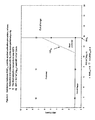
- FIGURE 1 shows a temperature programmed reduction ('TPR') profile of the cobalt catalyst precursor X1 of Example 1 (reduction at atmospheric pressure; reducing gas = pure hydrogen; linear heating rate of 2 °C/min; total feed gas rate of 10.7 m3 n/kgCohr; fixed bed operated under differential conditions that approach the near-gradientless conditions of fluidised beds);
- FIGURE 2 is a schematic graphical drawing, on which data applicable to the cobalt catalyst precursor X1 are superimposed, to illustrate the definitions of 'undesired', 'preferred', and 'most preferred' ranges for allowable combinations of HR1 and SV1;
- FIGURE 3 is a schematic graphical drawing, on which data applicable to the cobalt catalyst precursor X1 are superimposed, to illustrate the definitions of 'p referred' , and 'mo st preferred' ranges for allowable combinations of HR2 and SV2 at a specific set of (HR1,SV1) values, viz HR1 = 1.0°C/min and SV1 = 13.7m3 n/(kgCo.h).
-
- As a specific example of a catalyst precursor X, a 30gCo/100g Al2O3 proprietary slurry phase Fischer-Tropsch synthesis catalyst of the Applicant, as fully described in WO 01/39882, is considered. If the pre-reduced catalyst precursor or intermediate (labelled as X1), having been prepared according to this strict procedure, is furthermore subjected to the following benchmark reduction procedure:
- Fixed bed (20mm internal diameter) reduction of 15 ± 5g of the catalyst precursor X1 (ie pre-reduction catalyst mass), at atmospheric pressure, utilizing an undiluted H2 reducing gas (purity of 5.0) as total feed at a space velocity of 1300mln per gram reducible cobalt per hour, whilst applying the following temperature program: heat from 25°C to 425°C at 1°C/min, and hold isothermally at 425°C for 16 hours, the following Arrhenius pre-exponential factor is established:
-
- A representative batch of this pre-reduced catalyst precursor (ie precursor X1) was specifically prepared as follows: A solution of 17.4kg of Co(NO3)2.6H2O, 9.6g of (NH3)4Pt(NO3)2, and 11kg of distilled water was mixed with 20.0kg of a gamma alumina support (
Puralox SCCa 5/150, pore volume of 0.48ml/g, from SASOL Germany GmbH of Uberseering 40, 22297 Hamburg, Germany) by adding the support to the solution. The slurry was added to a conical vacuum drier and continuously mixed. The temperature of this slurry was increased to 60°C after which a pressure of 20kPa(a) was applied. During the first 3 hours of the drying step, the temperature was increased slowly and reached 95°C after 3 hours. After 3 hours the pressure was decreased to 3-15kPa(a), and a drying rate of 2.5m%/h at the point of incipient wetness was used. The complete impregnation and drying step took 9 hours, after which the impregnated and dried catalyst support was immediately and directly loaded into a fluidised bed calciner. The temperature of the dried impregnated catalyst support was about 75 °C at the time of loading into the calciner. The loading took about 1 to 2 minutes, and the temperature inside the calciner remained at its set point of about 75 °C. The dried impregnated catalyst support was heated from 75°C to 250 °C, using a heating rate of 0.5°C/min and an air space velocity of 1.0 m3 n/kg Co(NO3)2.6H2O/h, and kept at 250°C for 6 hours. To obtain a catalyst with a cobalt loading of 30gCo/100gAl2O3, a second impregnation/drying/calcination step was performed. A solution of 9.4kg of Co(NO3)2.6H2O, 15.7g of (NH3)4Pt(NO3)2, and 15.1kg of distilled water was mixed with 20.0kg of the catalyst precursor from the first impregnation and calcination, by adding the catalyst precursor to the solution. The slurry was added to a conical vacuum drier and continuously mixed. The temperature of this slurry was increased to 60°C after which a pressure of 20kPa(a) was applied. During the first 3 hours of the drying step, the temperature was increased slowly and reached 95 °C after 3 hours. After 3 hours the pressure was decreased to 3-15kPa(a), and a drying rate of 2.5m%/h at the point of incipient wetness was used. The complete impregnation and drying step took 9 hours, after which the treated catalyst support was immediately and directly loaded into the fluidised bed calciner. The temperature of the dried impregnated catalyst support was about 75°C at the time of loading into the calciner. The loading took about 1 to 2 minutes, and the temperature inside the calciner remained at its set point of about 75°C. The dried impregnated catalyst was heated from 75°Cto 250°C, using a heating rate of 0.5°C/min and an air space velocity of 1.0 m3 n/kg Co(NO3)2.6H2O/h, and kept at 250°C for 6 hours. A supported cobalt catalyst precursor on an alumina support was thus obtained. - A temperature programmed reduction ('TPR') experiment was performed with the cobalt catalyst precursor of Example 1, ie with catalyst precursor X1. The TPR experiment was performed at atmospheric pressure, using a heating rate ('HR') of 2°C/min, and a pure hydrogen feed rate of approximately 10.7 m3 n/kgCohr, in a fixed bed reactor. The results are presented in Figure 1. It can be seen from Figure 1 that the activation takes place in two activation stages with the end of
activation stage 1 defined by T* =250°C. - Cobalt catalyst precursors, as prepared in Example 1, were reduced according to different activation procedures, as given in Table 1 and Table 2, and subjected to the following Fischer-Tropsch synthesis test:
- Between 10g and 30g of the resultant reduced catalyst, ranging between 38micron to 150micron, was suspended in 300ml molten wax and loaded in a CSTR with an internal volume of 500ml. The feed gas consisted of hydrogen and carbon monoxide in a H2/CO molar ratio from 1.5/1 to 2.3/1. This reactor was electrically heated and sufficiently high stirrer speeds were employed so as to eliminate any gas-liquid mass transfer limitations. The feed flow was controlled by means of Brooks mass flow controllers, and space velocities ranging from 2 to 4m3 n/kgcathr were used. GC analyses of the permanent gases as well as the volatile overhead hydrocarbons were used in order to characterize the product spectra.
-
- The respective RIAFX1,i were estimated from these slurry phase CSTR Fischer-Tropsch synthesis runs, as given in Table 5, and correlated with the selected activation procedures of Table 1 and Table 2, as portrayed in Figure 2 and Figure 3.
- Cobalt catalyst precursors, as prepared in Example 1, were reduced in hydrogen feedgas of distinct dewpoint, as given in Table 3, and subjected to the Fischer-Tropsch synthesis test described in Example 3. The respective RIAFX1,i were estimated from these slurry phase CSTR Fischer-Tropsch synthesis runs, as given in Table 5.
- Cobalt catalyst precursors, as prepared in Example 1, were reduced in feed gas of distinct hydrogen content, as given in Table 4, and subjected to the Fischer-Tropsch synthesis test described in Example 3. The respective RIAFX1,i were estimated from these slurry phase CSTR Fischer-Tropsch synthesis runs, as given in Table 5.
Correlation between RIAF x1,i and the applied activation procedure, where:
i) Reduction was achieved with H2 of the more preferred purity
ii) The final reduction temperature was 425°C.SV c
(m 3 n /kg Co .h)HR c
(°C/min)Fischer-Tropsch synthesis data Synthesis run number RIAF x1,i Performance indicator 1.4 1.0 125£ 1.0 Preferred 1.8 0.3 529F 1.0 Preferred 1.8 1.0 332F 1.0 Preferred 239 (SR3) 0.8 1.8 2.5 250(SR3) 0.7 Undesired 1.8 5.0 240(SR3) 0.7 Undesired 1.8 7.5 248(SR3) 0.7 Undesired 6.8 2.0 393F 1.0 Preferred 7.5 2.5 253(SR3) 1.0 Preferred 7.5 5.0 254(SR3) 1.0 Preferred 7.5 7.5 255(SR3) 0.9 Preferred 8.2 2.0 394F 0.9 Preferred 8.9 2.0 352F 1.0 Most preferred 387F 1.1 11.6 2.0 351F 1.0 Most Preferred 385F 1.1 13.7 1.0 15£ 1.1 Most Preferred 126£ 1.1 242(SR3) 1.0 241 (SR3) 1.1 37# 1.1 38# 1.1 13.7 2.5 238(SR3) 1.0 Preferred 13.7 5.0 20£ 1.0 Preferred 236(SR3) 1.0 17.6 1.0 129£ 1.0 Most Preferred 234(SR3) 1.1 235(SR3) 1.1 27.4 2.0 381F 1.2 Most Preferred 379F 1.0 Correlation between RIAF x1,i and the applied activation procedure, where:
i) Reduction was achieved with H2 of the more preferred purity
ii) The final reduction temperature was 425°C.
iii) SV1 = 13.7 m3 n/kgco.h.
HR1 = 1.0°C/minSV2
(m 3 n /kg Co .h)HR2
(°C/min)Fischer-Tropsch synthesis data Synthesis run number RIAF x1,i Performance indicator 13.7 1.0 15£ 1.1 Most Preferred 126£ 1.1 242(SR3) 1.0 241(SR3) 1.1 37# 1.1 38# 1.1 13.7 5.0 61£ 1.2 Most Preferred 33# 1.2 13.7 7.5 257(SR3) 1.0 Preferred 7.5 1.0 251(SR3) 0.9 Preferred 7.5 7.5 31# 1.0 Preferred 1.8 1.0 252(SR3) 1.0 Preferred 1.8 7.5 30# 0.9 Preferred Correlation between RIAF x1,i and the hydrogen feedgas dewpoint during catalyst activation, where:
i) Reduction was achieved with a total feedgas containing ≥ 97 vol% hydrogen
ii) The final reduction temperature was 425°C.
ii) SV2 = SV1 and HR2 = HR1Dewpoint of total feed (°C) SV c
(m 3 n /kg Co .h)HR c
(°C/min)Fischer-Tropsch synthesis data Synthesis run number RIAF x1,i Performance indicator ≤ -30 1.8 1.0 332F 1.0 Preferred 239(SR3) 0.8 15 1.8 1.0 532F 0.7 Undesired 24 1.8 1.0 533F 0.7 Undesired Correlation between RIAF x1,i and the hydrogen content of the total feed during catalyst activation, where:
i) Reduction was achieved with a total feedgas of which the dewpoint was ≤ -30°C
ii) The final reduction temperature was 425°C.
iii) SV2 = SV1 and HR2 = HR1Hydrogen Content of total feed (vol%) SV c
(m 3 n /kg Co .h)HR c
(°C/min)Fischer-Tropsch synthesis data Synthesis run number RIAF x1,i Performance indicator Most preferred ≥97 13.7 1.0 15£ 1.1 126£ 1.1 242(SR3) 1.0 241(SR3) 1.1 37# 1.1 38# 1.1 90 13.7 1.0 530F 1.1 Most preferred 


- The feed gas space velocity during catalyst activation is the normal volume of reducing gas fed to the reactor per unit time and per unit mass of reducible cobalt (m3 n/kgCo.hr) during
activation stage 1 andactivation stage 2, where the subscript Co refers to reducible cobalt. In contrast, the feed gas space velocity during Fischer-Tropsch synthesis runs refers to the normal volume of total feed gas fed to the reactor per unit time per unit mass of the calcined catalyst. - In effecting the catalyst precursor reduction in accordance with the invention, the various phases that occur during loading of a reduction reactor in which the reduction is effected and during the heating program, which may include several hold times, to a final temperature not exceeding 600°C, preferably a final temperature not exceeding 500°C, and most preferably a final temperature not exceeding 450°C, a hold time at the final temperature, followed by cooling to the unloading temperature not exceeding 180°C and typically about ambient temperature, are as follows:
- A drying phase precedes the first activation stage. During the drying phase, the following combinations of process conditions (gas environment and temperature) are allowable: a dynamic pure hydrogen gas environment (with a preferred dewpoint ≤4°C, more preferred ≤ -30°C), and a temperature slightly lower than the temperature that will typify the onset of
stage 1 activation, but at the same time a temperature high enough that the drying phase (ie the quantitative removal of moisture that was adsorbed during storage and/or handling) will complete within an hour ; or a dynamic inert gas, eg pure nitrogen, environment (with a preferred dewpoint ≤4°C, more preferred ≤ - 30°C), and a temperature high enough (but not exceeding the calcination temperature applied during the preparation of the pre-reduction catalyst precursor) that the drying phase will complete within an hour. The drying phase is considered completed by the time the delta dew point (ie dewpoint of tail gas - dewpoint of total feed gas) ≤ 2°C. Once the delta dewpoint during a dynamic inert gas drying step has fallen off below 2°C, the inert gas is to be replaced by pure hydrogen at a temperature slightly lower than the temperature that will typify the onset ofstage 1 activation, to be followed by the application of HR1. Once the delta dewpoint during a dynamic pure hydrogen gas drying step has fallen off below 2°C, the application of HR1 can follow.
Activation stage 1 starts with the subjection of the pure pre-reduction catalyst precursor (ie the intermediate product containing all the reducible cobalt as labilized cobalt oxide in the absence of any matter that was accumulated during storage and/or handling, such as physically adsorbed moisture) to a pure hydrogen environment at SV1 with the immediate application of HR1.
Activation stage 1 ends at a temperature (for a specific heating program) when all reducible cobalt has been reduced to the 2 + oxidation state. This can be determined by deconvolving a typical TPR profile obtained under the same heating program. The result of such a deconvolution is shown in Figure 1, where T* signals the end ofactivation stage 1. This temperature T* will be higher than the temperature of the valley between the two peaks.
Activation stage 2: The reaching of a reduction bed temperature of T* (Figure 1) by means of HR1 signals the start of the second reduction stage. This stage ends at a temperature not exceeding 600°C, preferably not exceeding 500°C, and most preferably not exceeding 450°C when a desired degree of reduction with respect to reducible cobalt has been obtained. Preferably a desired degree of reduction with respect to reducible cobalt is obtained between 50% to 100%, more preferably between 60% and 80%. - A cooling phase commences directly after the completion of
activation stage 2, and is also performed under a pure hydrogen environment. The reduction bed temperature is allowed to cool down to a temperature ≤ Tc in the presence of a pure hydrogen environment. At a temperature ≤ Tc the pure hydrogen environment could be replaced with a 100% inert environment (i.e. H2 and O2 free, e.g. pure N2), after which the fully activated catalyst can be coated with Fischer-Tropsch synthesis reactor wax in the manner described in ZA 2000/5666. - Figures 2 and 3 were generated from the values given in Tables 1 and 2. Figure 2 illustrates the definitions of 'undesired', 'preferred' and 'most preferred' ranges referred to hereinbefore, for allowable combinations of HR1 and SV1. Figure 3 illustrates the definitions of 'preferred' and 'most preferred' ranges referred to hereinbefore, tor allowable combinations of HR2 and SV2 for the case where HR1 = 1.0°C/min, and SV1 = 13.7m3 n/(kgCo.h). It will be appreciated that a separate graph, similar to Figure 3, will have to be prepared for each selected set of (HR1, SV1).
- From prior art in this field, it was expected that an activation process to obtain a Fischer-Tropsch cobalt supported catalyst with a high intrinsic activity would involve:
- The metal precursor, after a final preparation step, typically a final calcination step, being predominantly Co3O4;
- The reduction rate of Co3O4 being inhibited by the presence of water vapour; the activation conditions, such as gas space velocities and heating rates, would thus be set to ensure that water partial pressure levels remained below certain limits at all times during the activation process;
- The activation (reduction) of Co3O4 to its metal state not being effected in a single event or stage but proceeding by way of a plurality, eg two, consecutive stages; and
- Either pure hydrogen, or diluted hydrogen containing inert diluents such as nitrogen, being used
- However, the Applicant has thus now surprisingly found that
- If the metal precursor, after the final preparation step, such as a final impregnation and calcination step, and at the start of the activation process, is not Co3O4, then the teachings of the prior art on how to activate cobalt oxide precursors, consisting mainly of Co3O4, to Fischer-Tropsch cobalt supported catalysts with a high intrinsic activity, may not be applicable ;
- The rate of reduction of the metal precursor when it is Co3O4, and the quantification of the inhibiting effect of water vapour on this rate, as known from the prior art, does not apply when the metal precursor is not Co3O4. Also, the activation conditions, eg gas space velocities and heating rates, derived for the case of Co3O4, ie to keep the water partial pressure below certain limits, does not apply when the metal precursor is not Co3O4;
- During the activation process at elevated temperatures only pure hydrogen should be used; and
- If the metal precursor is activated to its metal state in two or more
consecutive activation stages, it is possible to drop globally set, ie
applicable to all the activation stages, activation conditions in favour of
locally set, ie applicable to a single activation stage, activation
conditions. The particular chemical species that characterise the start
and end of any specific activation stage, the rate of reduction during
that stage, and the inhibiting effect of water vapour on the rate of
reduction during that stage, determine the locally set activation
conditions for that stage. For example, the negative effect of a build-up
of water vapour on catalyst activity may be more pronounced for an
earlier stage than for a later stage. Thus, the earlier stage(s) would not
be able to tolerate as low space velocities (eg to reduce hydrogen pump-around)
and as high heating rates (eg to reduce the overall reduction
time) as the later stage(s), and still keep the water partial pressure
during these stage in check. In other words, in the process according to
the invention for producing a Fischer-Tropsch synthesis catalyst, more
water will be produced per reducible cobalt atom (be it from the
reduction of nitrates, from the reduction of carbonates, and/or from the
reduction of cobalt oxides of higher oxidation state to a cobalt (II) oxide)
than what can be expected of Co3O4, during the first activation stage.
- The rate of production of water is higher (possibly because the preferred labilized cobalt oxide phase(s) is more porous) than for the case of Co3O4, for the first stage of activation;
- This means that the control over water partial pressure is considered to be more challenging during the first activation stage (compared to the case for Co3O4), than during the second activation stage, necessitating lower heating rates/higher space velocities during the first activation stage.
- The Inventors have thus developed an activation procedure for supported cobalt catalysts, resulting in excellent Fischer-Tropsch synthesis behaviour. It was surprisingly found that the activation of supported cobalt catalyst precursors, wherein all the reducible cobalt can be represented by a formula unit that contains more than 4/3 moles of oxygen atoms per mole of cobalt atoms and specifically CoOaHb where a≥1.7 and b>0 as disclosed in WO 01/39882A1, or monometal hydrotalcite-like compounds of Coii 0.74 Coiii 0.26 (OH)2.01 (NO3)0.21 (CO3)0.02 0.6 H2O and Coii 0.74 Coiii 0.26 (OH)1.99 (CO3)0.13 (NO3)0.01 0.7 H2O as described in: Chem. Matter.; 2000; 12; 3459-3465), can be performed in a 2 stage activation procedure, in which the second activation step has a higher heating rate and/or a lower feed gas space velocity.
HRC,1 is defined as the maximum value of HRc that will result in a RIAFx,i ≥ 0.8 at selected values of SVc, thus implying that HRC,1 = f(SVc).
HRC,2 is defined as the maximum value of HRc that will result in a RIAFx,i ≥ 1.0 at selected values of SVc, thus implying that HRC,2 = f(SVc).
Undesired, preferred and most preferred ranges for HR1 are defined as:
0 < HR1 < HRC,2 is most preferred,
HRC,2 ≤ HR1 ≤ HRC,1 is preferred,
and HR1 > HRC,1 is undesired.
Claims (12)
- A process for producing a supported Fischer-Tropsch catalyst, which process includes
treating, in a first activation stage, a particulate pre-reduction cobalt supported Fischer-Tropsch synthesis catalyst precursor which comprises a catalyst support impregnated with cobalt and containing reducible supported or labilized cobalt oxide in a calcined state and selected from formula-units comprising CoOaHb, where a ≥ 1.7 and b > 0, a monometal hydrotalcite-like compound having a formula-unit Coii 0.74 Coiii 0.26 (OH)2.01(NO3)0.21 (CO3)0.02 0.6 H2O, and a monometal hydrotalcite-like compound having a formula-unit Coii 0.74 Coiii 0.26 (OH)1.99 (Co3)0.13 (NO3)0.01 0.7 H2O in which each mole of cobalt atoms is associated with more than 4/3 moles of oxygen atoms and displays a reducible cobalt oxide specific surface area at least equal to that of Co3O4 spinel, with a pure hydrogen reducing gas, at a first specific feed gas space velocity, SV1, and at a first heating rate, HR1, to obtain a partially reduced catalyst precursor; and
thereafter treating the partially reduced catalyst precursor, in a second activation stage, with a pure hydrogen reducing gas, at a second specific feed gas space velocity, SV2, and at a second heating rate, HR2, to obtain an activated supported Fischer-Tropsch catalyst, where SV2≤SV1 and/or HR2≥HR1, provided that when SV2=SV1, HR2≠HR1 and when HR2=HR1, SV2≠SV1. - A process according to Claim 1 wherein the treatments in the first and second activation stages are effected by using a fluidized bed of the catalyst precursor particles, with the reducing gas acting as a fluidizing medium for fluidizing the bed of particles.
- A process according to Claim 1 or Claim 2, wherein (i) a constant space velocity is maintained during the treatment in the first activation stage so that SV1 is constant, and (ii) a constant space velocity is maintained during the treatment in the second activation stage so that SV2 is constant, with SV2≤SV1.
- A process according to Claim 3, wherein (i) a constant heating rate is maintained during the treatment in the first activation stage so that HR1 is constant, and (ii) a constant heating rate is maintained during the treatment in the second activation stage so that HR2 is constant, with HR2 ≥ HR1.
- A process according to Claim 3 or Claim 4, wherein RIAFx,i for the catalyst is at least 0.8.
- A process according to Claim 3 or Claim 4, wherein RIAFx,i for the catalyst is greater than 1.0.
- A process according to any one of Claims 3 to 6 inclusive, wherein the first activation stage commences at the same temperature as the onset of reduction of the reducible cobalt, when the production of water is for the first time accompanied by the consumption of hydrogen, with the first activation stage treatment being continued until all of the reducible cobalt has been converted quantitatively to CoO at a bed temperature which has a value in the range of 150°C to 280°C, so that, at the commencement of the second activation stage treatment, the temperature in the second activation stage is at said value in the range 150°C to 280°C, and with the second activation stage treatment being continued until the temperature in the second treatment stage has a value in the range of 300°C to 600°C.
- A process according to Claim 1 or Claim 2, wherein the feed gas space velocities during the treatments in the first and/or the second activation stages are non-constant or variable.
- A process according to Claim 8, wherein RIAFx,i for the catalyst is at least 0.8.
- A process according to Claim 8, wherein RIAFx,i for the catalyst is greater than 1.0.
- A process according to any one of Claims 1 to 10 inclusive, wherein the pure hydrogen reducing gas which is used in the first and the second activation stages is a hydrogen containing gas mixture comprising ≥ 90vol% H2 and ≤ 10vol% inerts, with the dewpoint of the pure hydrogen reducing gas being <4°C.
- A process according to any one of Claims 1 to 11 inclusive, wherein the treatments in both the first and second activation stages are effected at between 0.6 and 1.5 bar(a).
Applications Claiming Priority (3)
| Application Number | Priority Date | Filing Date | Title |
|---|---|---|---|
| ZA200108815 | 2001-10-25 | ||
| ZA200108815 | 2001-10-25 | ||
| PCT/IB2002/004432 WO2003035257A1 (en) | 2001-10-25 | 2002-10-25 | Process for activating cobalt catalysts |
Publications (2)
| Publication Number | Publication Date |
|---|---|
| EP1444040A1 EP1444040A1 (en) | 2004-08-11 |
| EP1444040B1 true EP1444040B1 (en) | 2005-06-29 |
Family
ID=25589359
Family Applications (1)
| Application Number | Title | Priority Date | Filing Date |
|---|---|---|---|
| EP02801984A Revoked EP1444040B1 (en) | 2001-10-25 | 2002-10-25 | Process for activating cobalt catalysts |
Country Status (13)
| Country | Link |
|---|---|
| US (1) | US7592289B2 (en) |
| EP (1) | EP1444040B1 (en) |
| JP (1) | JP2005506190A (en) |
| AR (1) | AR037036A1 (en) |
| AT (1) | ATE298630T1 (en) |
| AU (1) | AU2002363102B2 (en) |
| BR (1) | BR0210813A (en) |
| DE (1) | DE60204907T2 (en) |
| NL (1) | NL1021752C2 (en) |
| NO (1) | NO20035640L (en) |
| RU (1) | RU2301110C2 (en) |
| WO (1) | WO2003035257A1 (en) |
| ZA (1) | ZA200309694B (en) |
Cited By (1)
| Publication number | Priority date | Publication date | Assignee | Title |
|---|---|---|---|---|
| US8062992B2 (en) | 2007-05-04 | 2011-11-22 | Sasol Technology (Proprietary) Limited | Catalysts |
Families Citing this family (36)
| Publication number | Priority date | Publication date | Assignee | Title |
|---|---|---|---|---|
| US7361619B2 (en) * | 2003-04-11 | 2008-04-22 | Exxonmobil Research And Engineering Company | Fischer-Tropsch catalyst production |
| US7045554B2 (en) | 2003-09-03 | 2006-05-16 | Conocophillips Company | Method for improved Fischer-Tropsch catalyst stability and higher stable syngas conversion |
| US7365040B2 (en) | 2004-04-26 | 2008-04-29 | Sasoltechnology (Proprietary) Limited | Catalysts |
| CN100537025C (en) | 2005-01-11 | 2009-09-09 | 萨索尔技术(控股)有限公司 | Producing supported cobalt catalysts for the fischer-tropsch synthesis |
| RU2456080C2 (en) * | 2007-05-11 | 2012-07-20 | Сасол Текнолоджи (Проприетери) Лимитед | Method of regenerating fischer-tropsch synthesis cobalt catalyst |
| US20090005275A1 (en) * | 2007-06-28 | 2009-01-01 | Chevron U.S.A. Inc. | Power steering fluid |
| US20090062166A1 (en) | 2007-08-28 | 2009-03-05 | Chevron U.S.A. Inc. | Slideway Lubricant Compositions, Methods of Making and Using Thereof |
| US7956018B2 (en) * | 2007-12-10 | 2011-06-07 | Chevron U.S.A. Inc. | Lubricant composition |
| WO2010140077A2 (en) | 2009-06-03 | 2010-12-09 | Sasol Technology (Proprietary) Limited | Catalysts |
| US8349776B2 (en) * | 2009-09-29 | 2013-01-08 | Chevron Oronite Company Llc | Trunk piston engine lubricating oil compositions |
| FR2962664B1 (en) * | 2010-07-16 | 2014-03-14 | IFP Energies Nouvelles | COBALT CATALYST ON SILICA-ALUMINUM SUPPORT FOR FISCHER-TROPSCH SYNTHESIS |
| RU2445161C1 (en) * | 2010-08-19 | 2012-03-20 | Общество с ограниченной ответственностью "СинТоп" | Method of activation of cobalt catalyst of fischer-tropsch synthesis |
| US8455406B2 (en) | 2010-10-28 | 2013-06-04 | Chevron U.S.A. Inc. | Compressor oils having improved oxidation resistance |
| US8702968B2 (en) | 2011-04-05 | 2014-04-22 | Chevron Oronite Technology B.V. | Low viscosity marine cylinder lubricating oil compositions |
| CA2833079C (en) | 2011-04-28 | 2018-01-02 | Sasol Technology (Proprietary) Limited | Catalysts |
| EP2704827B1 (en) * | 2011-05-06 | 2021-02-17 | Sasol Technology (Proprietary) Limited | A process for preparing a cobalt-containing hydrocarbon synthesis catalyst precursor |
| RU2458736C1 (en) * | 2011-05-10 | 2012-08-20 | Учреждение Российской академии наук Институт катализа им. Г.К. Борескова Сибирского отделения РАН | Catalyst and method of producing hydrocarbons from carbon monoxide and hydrogen (versions) |
| US9050588B2 (en) | 2011-05-27 | 2015-06-09 | Gi—Gasification International, S.A. | Fischer-tropsch catalyst activation procedure |
| CN103120953B (en) * | 2011-11-18 | 2014-11-26 | 中国石油化工股份有限公司 | Disproportionation and alkyl transfer catalyst reducing method |
| US9206374B2 (en) | 2011-12-16 | 2015-12-08 | Chevron Oronite Sas | Trunk piston engine lubricating oil compositions |
| US20130172179A1 (en) * | 2011-12-31 | 2013-07-04 | Michelene Hall | Rejuvenable ceramic exhibiting intragranular porosity |
| CN104107703B (en) * | 2013-04-16 | 2016-08-24 | 中国石油化工股份有限公司 | Renovation process for olefin dismutation reaction catalyst |
| EP3066180B1 (en) | 2013-11-06 | 2021-01-13 | Chevron Oronite Technology B.V. | Marine diesel cylinder lubricant oil compositions |
| SG10201710483WA (en) | 2013-11-06 | 2018-02-27 | Chevron Oronite Tech Bv | Marine diesel cylinder lubricant oil compositions |
| WO2015140099A1 (en) * | 2014-03-17 | 2015-09-24 | Shell Internationale Research Maatschappij B.V. | A method for start-up and operation of a fischer-tropsch reactor |
| EA033031B1 (en) | 2014-03-17 | 2019-08-30 | Шелл Интернэшнл Рисерч Маатсхаппий Б.В. | Method for start-up and operation of a fischer-tropsch reactor |
| WO2016091694A1 (en) | 2014-12-12 | 2016-06-16 | Bp P.L.C. | Process for producing a supported, partially reductively activated fischer-tropsch synthesis catalyst, and process for producing hydrocarbons using the same |
| WO2016091695A1 (en) | 2014-12-12 | 2016-06-16 | Bp P.L.C. | Process for producing a reductively activated fischer-tropsch synthesis catalyst, and process for producing hydrocarbons using the same |
| WO2016091692A1 (en) | 2014-12-12 | 2016-06-16 | Bp P.L.C. | Process for producing a supported reductively activated fischer-tropsch synthesis catalyst, and process for producing hydrocarbons using the same |
| KR102403745B1 (en) | 2015-07-22 | 2022-05-31 | 셰브런 오로나이트 테크놀로지 비.브이. | Marine Diesel Cylinder Lubricating Oil Composition |
| JP6741694B2 (en) * | 2016-01-29 | 2020-08-19 | Eneos株式会社 | Fischer-Tropsch synthesis catalyst, method for producing Fischer-Tropsch synthesis catalyst, and method for producing hydrocarbon |
| GB201702248D0 (en) | 2017-02-10 | 2017-03-29 | Bp Plc | Start-up procedure for a fischer-tropsch process |
| FR3064498B1 (en) | 2017-03-30 | 2021-10-29 | Ifp Energies Now | COBALT-BASED CATALYSTS PREPARATION PROCESS |
| FR3085284B1 (en) * | 2018-09-04 | 2021-05-07 | Ifp Energies Now | PROCESS FOR PREPARING A CATALYST OR A COLLECTION MASS FROM MELTED SALTS |
| US10434506B1 (en) | 2018-12-18 | 2019-10-08 | Emerging Fuels Technology, Inc. | Method for activation or regeneration of a catalyst |
| US20230015935A1 (en) * | 2021-07-15 | 2023-01-19 | Emerging Fuels Technology, Inc. | Method for the activation or rejuvenation of a catalyst |
Family Cites Families (41)
| Publication number | Priority date | Publication date | Assignee | Title |
|---|---|---|---|---|
| US4729981A (en) | 1981-10-13 | 1988-03-08 | Shell Internationale Research Maatschappij B.V. | ROR-activated catalyst for synthesis gas conversion |
| US4585798A (en) | 1981-10-13 | 1986-04-29 | Gulf Research & Development Company | Synthesis gas conversion using ruthenium-promoted cobalt catalyst |
| US4399234A (en) | 1981-10-13 | 1983-08-16 | Gulf Research & Development Company | Process for preparing gasoline range hydrocarbons from synthesis gas and catalyst used therefor |
| DE3465169D1 (en) | 1984-01-31 | 1987-09-10 | Shell Int Research | Catalyst activation |
| IN165116B (en) | 1984-07-20 | 1989-08-19 | Shell Int Research | |
| US4717702A (en) | 1985-04-26 | 1988-01-05 | Shell Internationale Research Maatschappij Bv | Catalyst for conversion of synthesis gas to diesel fuel and process for preparation of such catalyst |
| US4858798A (en) * | 1988-02-29 | 1989-08-22 | Motorola, Inc. | Carry case with quick release and self locating retainer apparatus |
| US5036032A (en) | 1988-03-25 | 1991-07-30 | Exxon Research And Engineering Company | Selective catalysts and their preparation for catalytic hydrocarbon synthesis |
| JP2933636B2 (en) * | 1989-05-12 | 1999-08-16 | 富士石油株式会社 | Catalyst and method for hydrodealkylation of alkyl aromatic compounds |
| US5258411A (en) * | 1990-10-15 | 1993-11-02 | Exxon Research And Engineering Co. | Activation conditions to maximize the HCS activity of supported cobalt catalysts (OP-3706) |
| EP0554348B1 (en) | 1990-10-15 | 1998-06-03 | Exxon Research And Engineering Company | Method for preparing cobalt-containing hydrocarbon synthesis catalyst |
| US5168091A (en) | 1990-10-15 | 1992-12-01 | Exxon Research And Engineering Company | Activation conditions to maximize the HSC activity of supported cobalt catalysts |
| GB9114314D0 (en) * | 1991-07-02 | 1991-08-21 | British Petroleum Co Plc | Catalyst treatment for fisher-tropsch process |
| GB9117948D0 (en) | 1991-08-20 | 1991-10-09 | Shell Int Research | Process for the activation of a catalyst |
| GB9117899D0 (en) | 1991-08-20 | 1991-10-09 | Shell Int Research | Process for the activation of a catalyst |
| US5292705A (en) | 1992-09-24 | 1994-03-08 | Exxon Research & Engineering Co. | Activation of hydrocarbon synthesis catalyst |
| DZ2013A1 (en) | 1995-04-07 | 2002-10-23 | Sastech Ltd | Catalysts. |
| NO313086B1 (en) * | 1995-08-04 | 2002-08-12 | Inst Francais Du Petrole | Process for preparing a catalyst, catalyst obtainable therewith, catalyst mixture obtained thereby, and process for the synthesis of hydrocarbons |
| PE31698A1 (en) | 1995-11-08 | 1998-06-15 | Shell Int Research | CATALYST ACTIVATION AND REJUVENATION PROCESS |
| WO1999017874A1 (en) * | 1997-10-08 | 1999-04-15 | Corning Incorporated | Method of making activated carbon-supported catalysts |
| AU735070B2 (en) | 1997-12-30 | 2001-06-28 | Shell Internationale Research Maatschappij B.V. | Cobalt based fisher-tropsch catalyst |
| US5929126A (en) * | 1998-01-30 | 1999-07-27 | Exxon Research And Engineering Co. | Gas conversion with rejuvenation ammonia removal |
| DZ2724A1 (en) | 1998-02-20 | 2003-09-01 | Sasol Tech Pty Ltd | Process for the production of hydrocarbons from a synthesis gas and their catalysts. |
| WO1999061550A1 (en) | 1998-05-27 | 1999-12-02 | Energy International Corporation | Improved fischer-tropsch activity for 'non-promoted' cobalt-on-alumina catalysts |
| CZ20011201A3 (en) * | 1998-10-05 | 2001-10-17 | Sasol Technology (Proprietary) Limited | Process for preparing catalyst precursor |
| DE59913717D1 (en) * | 1998-11-09 | 2006-09-07 | Argillon Gmbh | CATALYST BODIES AND METHOD FOR REDUCING HALOGENATED HYDROCARBONS |
| US6262132B1 (en) | 1999-05-21 | 2001-07-17 | Energy International Corporation | Reducing fischer-tropsch catalyst attrition losses in high agitation reaction systems |
| US6239184B1 (en) * | 1999-09-22 | 2001-05-29 | Syntroleum Corporation | Extended catalyst life Fischer-Tropsch process |
| ZA200005666B (en) | 1999-10-14 | 2001-05-15 | Sasol Tech Pty Ltd | Handling of a catalyst. |
| US6869978B2 (en) * | 1999-11-17 | 2005-03-22 | Conocophillips Company | Pressure swing catalyst regeneration procedure for Fischer-Tropsch catalyst |
| US6486220B1 (en) * | 1999-11-17 | 2002-11-26 | Conoco Inc. | Regeneration procedure for Fischer-Tropsch catalyst |
| WO2001039882A1 (en) * | 1999-12-01 | 2001-06-07 | Sasol Technology (Proprietary) Limited | Cobalt catalysts |
| ATE370212T1 (en) * | 2000-06-12 | 2007-09-15 | Sasol Tech Pty Ltd | METHOD FOR PRODUCING HYDROCARBONS USING COBALT CATALYSTS |
| CN1444507A (en) * | 2000-07-24 | 2003-09-24 | 萨索尔技术(控股)有限公司 | Production of hydrocarbons from synthesis gas |
| US6559191B1 (en) * | 2000-09-01 | 2003-05-06 | Exxonmobil Research And Engineering Company | Carbon monoxide hydrogenation (JSS-0004) |
| US6800579B2 (en) * | 2002-01-29 | 2004-10-05 | Exxonmobil Research And Engineering Company | Catalyst regeneration |
| US6753354B2 (en) * | 2002-01-29 | 2004-06-22 | Exxonmobil Research And Engineering Company | Fischer-tropsch catalyst enhancement |
| US6777451B2 (en) * | 2002-01-29 | 2004-08-17 | Exxonmobil Research And Engineering Company | Catalyst enhancement |
| US6596781B1 (en) * | 2002-05-02 | 2003-07-22 | Chevron U.S.A. Inc. | Integrated process for preparing Fischer-Tropsch products and acetic acid from synthesis gas |
| WO2004026796A2 (en) * | 2002-09-20 | 2004-04-01 | Conocophillips Company | Slurry activation of fischer-tropsch catalyst with carbon monoxide co-feed |
| CA2500546A1 (en) * | 2002-10-16 | 2004-04-29 | Conocophillips Company | Fischer-tropsch processes and catalysts made from a material comprising boehmite |
-
2002
- 2002-10-25 WO PCT/IB2002/004432 patent/WO2003035257A1/en active IP Right Grant
- 2002-10-25 JP JP2003537812A patent/JP2005506190A/en active Pending
- 2002-10-25 AR ARP020104065A patent/AR037036A1/en not_active Application Discontinuation
- 2002-10-25 AT AT02801984T patent/ATE298630T1/en not_active IP Right Cessation
- 2002-10-25 NL NL1021752A patent/NL1021752C2/en not_active IP Right Cessation
- 2002-10-25 EP EP02801984A patent/EP1444040B1/en not_active Revoked
- 2002-10-25 RU RU2004106789/04A patent/RU2301110C2/en not_active IP Right Cessation
- 2002-10-25 DE DE60204907T patent/DE60204907T2/en not_active Expired - Fee Related
- 2002-10-25 BR BR0210813-5A patent/BR0210813A/en not_active IP Right Cessation
- 2002-10-25 AU AU2002363102A patent/AU2002363102B2/en not_active Ceased
- 2002-10-25 US US10/480,778 patent/US7592289B2/en not_active Expired - Fee Related
-
2003
- 2003-12-12 ZA ZA200309694A patent/ZA200309694B/en unknown
- 2003-12-17 NO NO20035640A patent/NO20035640L/en not_active Application Discontinuation
Cited By (2)
| Publication number | Priority date | Publication date | Assignee | Title |
|---|---|---|---|---|
| US8062992B2 (en) | 2007-05-04 | 2011-11-22 | Sasol Technology (Proprietary) Limited | Catalysts |
| US8067333B2 (en) | 2007-05-04 | 2011-11-29 | Sasol Technology (Proprietary) Limited | Catalysts |
Also Published As
| Publication number | Publication date |
|---|---|
| DE60204907T2 (en) | 2006-04-20 |
| JP2005506190A (en) | 2005-03-03 |
| AR037036A1 (en) | 2004-10-20 |
| EP1444040A1 (en) | 2004-08-11 |
| AU2002363102B2 (en) | 2006-11-23 |
| NL1021752C2 (en) | 2003-06-11 |
| DE60204907D1 (en) | 2005-08-04 |
| US7592289B2 (en) | 2009-09-22 |
| WO2003035257A1 (en) | 2003-05-01 |
| RU2301110C2 (en) | 2007-06-20 |
| NO20035640D0 (en) | 2003-12-17 |
| NL1021752A1 (en) | 2003-04-28 |
| ATE298630T1 (en) | 2005-07-15 |
| ZA200309694B (en) | 2004-09-28 |
| NO20035640L (en) | 2004-05-06 |
| RU2004106789A (en) | 2005-07-27 |
| US20050227866A1 (en) | 2005-10-13 |
| BR0210813A (en) | 2004-06-22 |
Similar Documents
| Publication | Publication Date | Title |
|---|---|---|
| EP1444040B1 (en) | Process for activating cobalt catalysts | |
| AU2002363102A1 (en) | Process for activating cobalt catalysts | |
| EP1289654B1 (en) | Process for preparing cobalt catalysts | |
| EP2155837B1 (en) | Catalysts | |
| US6806226B2 (en) | Cobalt catalysts | |
| AU2001262578A1 (en) | Cobalt catalysts | |
| EP1853382B1 (en) | Producing supported cobalt catalysts for the fischer-tropsch synthesis | |
| US7524787B2 (en) | Producing supported cobalt catalysts for the Fisher-Tropsch synthesis | |
| MC NL | VERFAHREN ZUR AKTIVIERUNG VON COBALTKATALYSATOREN PROCEDE D’ACTIVATION DE CATALYSEURS A BASE DE COBALT | |
| ZA200209617B (en) | Cobalt catalysts. |
Legal Events
| Date | Code | Title | Description |
|---|---|---|---|
| PUAI | Public reference made under article 153(3) epc to a published international application that has entered the european phase |
Free format text: ORIGINAL CODE: 0009012 |
|
| 17P | Request for examination filed |
Effective date: 20040114 |
|
| AK | Designated contracting states |
Kind code of ref document: A1 Designated state(s): AT BE BG CH CY CZ DE DK EE ES FI FR GB GR IE IT LI LU MC NL PT SE SK TR |
|
| AX | Request for extension of the european patent |
Extension state: AL LT LV MK RO SI |
|
| TCNL | Nl: translation of patent claims filed | ||
| GRAP | Despatch of communication of intention to grant a patent |
Free format text: ORIGINAL CODE: EPIDOSNIGR1 |
|
| GRAS | Grant fee paid |
Free format text: ORIGINAL CODE: EPIDOSNIGR3 |
|
| GRAA | (expected) grant |
Free format text: ORIGINAL CODE: 0009210 |
|
| AK | Designated contracting states |
Kind code of ref document: B1 Designated state(s): AT BE BG CH CY CZ DE DK EE ES FI FR GB GR IE IT LI LU MC NL PT SE SK TR |
|
| PG25 | Lapsed in a contracting state [announced via postgrant information from national office to epo] |
Ref country code: FI Free format text: LAPSE BECAUSE OF FAILURE TO SUBMIT A TRANSLATION OF THE DESCRIPTION OR TO PAY THE FEE WITHIN THE PRESCRIBED TIME-LIMIT Effective date: 20050629 Ref country code: LI Free format text: LAPSE BECAUSE OF FAILURE TO SUBMIT A TRANSLATION OF THE DESCRIPTION OR TO PAY THE FEE WITHIN THE PRESCRIBED TIME-LIMIT Effective date: 20050629 Ref country code: AT Free format text: LAPSE BECAUSE OF FAILURE TO SUBMIT A TRANSLATION OF THE DESCRIPTION OR TO PAY THE FEE WITHIN THE PRESCRIBED TIME-LIMIT Effective date: 20050629 Ref country code: TR Free format text: LAPSE BECAUSE OF FAILURE TO SUBMIT A TRANSLATION OF THE DESCRIPTION OR TO PAY THE FEE WITHIN THE PRESCRIBED TIME-LIMIT Effective date: 20050629 Ref country code: SK Free format text: LAPSE BECAUSE OF FAILURE TO SUBMIT A TRANSLATION OF THE DESCRIPTION OR TO PAY THE FEE WITHIN THE PRESCRIBED TIME-LIMIT Effective date: 20050629 Ref country code: CH Free format text: LAPSE BECAUSE OF FAILURE TO SUBMIT A TRANSLATION OF THE DESCRIPTION OR TO PAY THE FEE WITHIN THE PRESCRIBED TIME-LIMIT Effective date: 20050629 Ref country code: EE Free format text: LAPSE BECAUSE OF FAILURE TO SUBMIT A TRANSLATION OF THE DESCRIPTION OR TO PAY THE FEE WITHIN THE PRESCRIBED TIME-LIMIT Effective date: 20050629 Ref country code: CZ Free format text: LAPSE BECAUSE OF FAILURE TO SUBMIT A TRANSLATION OF THE DESCRIPTION OR TO PAY THE FEE WITHIN THE PRESCRIBED TIME-LIMIT Effective date: 20050629 Ref country code: BE Free format text: LAPSE BECAUSE OF FAILURE TO SUBMIT A TRANSLATION OF THE DESCRIPTION OR TO PAY THE FEE WITHIN THE PRESCRIBED TIME-LIMIT Effective date: 20050629 |
|
| REG | Reference to a national code |
Ref country code: GB Ref legal event code: FG4D |
|
| REG | Reference to a national code |
Ref country code: CH Ref legal event code: EP |
|
| REF | Corresponds to: |
Ref document number: 60204907 Country of ref document: DE Date of ref document: 20050804 Kind code of ref document: P |
|
| REG | Reference to a national code |
Ref country code: IE Ref legal event code: FG4D |
|
| PG25 | Lapsed in a contracting state [announced via postgrant information from national office to epo] |
Ref country code: DK Free format text: LAPSE BECAUSE OF FAILURE TO SUBMIT A TRANSLATION OF THE DESCRIPTION OR TO PAY THE FEE WITHIN THE PRESCRIBED TIME-LIMIT Effective date: 20050929 Ref country code: SE Free format text: LAPSE BECAUSE OF FAILURE TO SUBMIT A TRANSLATION OF THE DESCRIPTION OR TO PAY THE FEE WITHIN THE PRESCRIBED TIME-LIMIT Effective date: 20050929 Ref country code: BG Free format text: LAPSE BECAUSE OF FAILURE TO SUBMIT A TRANSLATION OF THE DESCRIPTION OR TO PAY THE FEE WITHIN THE PRESCRIBED TIME-LIMIT Effective date: 20050929 Ref country code: GR Free format text: LAPSE BECAUSE OF FAILURE TO SUBMIT A TRANSLATION OF THE DESCRIPTION OR TO PAY THE FEE WITHIN THE PRESCRIBED TIME-LIMIT Effective date: 20050929 |
|
| PG25 | Lapsed in a contracting state [announced via postgrant information from national office to epo] |
Ref country code: ES Free format text: LAPSE BECAUSE OF FAILURE TO SUBMIT A TRANSLATION OF THE DESCRIPTION OR TO PAY THE FEE WITHIN THE PRESCRIBED TIME-LIMIT Effective date: 20051010 |
|
| PG25 | Lapsed in a contracting state [announced via postgrant information from national office to epo] |
Ref country code: CY Free format text: LAPSE BECAUSE OF FAILURE TO SUBMIT A TRANSLATION OF THE DESCRIPTION OR TO PAY THE FEE WITHIN THE PRESCRIBED TIME-LIMIT Effective date: 20051025 Ref country code: IE Free format text: LAPSE BECAUSE OF NON-PAYMENT OF DUE FEES Effective date: 20051025 |
|
| PG25 | Lapsed in a contracting state [announced via postgrant information from national office to epo] |
Ref country code: LU Free format text: LAPSE BECAUSE OF NON-PAYMENT OF DUE FEES Effective date: 20051031 Ref country code: MC Free format text: LAPSE BECAUSE OF NON-PAYMENT OF DUE FEES Effective date: 20051031 |
|
| PG25 | Lapsed in a contracting state [announced via postgrant information from national office to epo] |
Ref country code: PT Free format text: LAPSE BECAUSE OF FAILURE TO SUBMIT A TRANSLATION OF THE DESCRIPTION OR TO PAY THE FEE WITHIN THE PRESCRIBED TIME-LIMIT Effective date: 20051207 |
|
| REG | Reference to a national code |
Ref country code: CH Ref legal event code: PL |
|
| PLBI | Opposition filed |
Free format text: ORIGINAL CODE: 0009260 |
|
| ET | Fr: translation filed | ||
| PLAX | Notice of opposition and request to file observation + time limit sent |
Free format text: ORIGINAL CODE: EPIDOSNOBS2 |
|
| 26 | Opposition filed |
Opponent name: BAWDEN, PETER CHARLES Effective date: 20060328 |
|
| NLR1 | Nl: opposition has been filed with the epo |
Opponent name: BAWDEN, PETER CHARLES |
|
| REG | Reference to a national code |
Ref country code: IE Ref legal event code: MM4A |
|
| PLAF | Information modified related to communication of a notice of opposition and request to file observations + time limit |
Free format text: ORIGINAL CODE: EPIDOSCOBS2 |
|
| PLBB | Reply of patent proprietor to notice(s) of opposition received |
Free format text: ORIGINAL CODE: EPIDOSNOBS3 |
|
| RDAF | Communication despatched that patent is revoked |
Free format text: ORIGINAL CODE: EPIDOSNREV1 |
|
| APBP | Date of receipt of notice of appeal recorded |
Free format text: ORIGINAL CODE: EPIDOSNNOA2O |
|
| APAH | Appeal reference modified |
Free format text: ORIGINAL CODE: EPIDOSCREFNO |
|
| APBQ | Date of receipt of statement of grounds of appeal recorded |
Free format text: ORIGINAL CODE: EPIDOSNNOA3O |
|
| PGFP | Annual fee paid to national office [announced via postgrant information from national office to epo] |
Ref country code: DE Payment date: 20081201 Year of fee payment: 7 |
|
| PGFP | Annual fee paid to national office [announced via postgrant information from national office to epo] |
Ref country code: IT Payment date: 20081023 Year of fee payment: 7 |
|
| RAP2 | Party data changed (patent owner data changed or rights of a patent transferred) |
Owner name: SASOL TECHNOLOGY (PROPRIETARY) LIMITED Owner name: BASF NEDERLAND B.V. |
|
| PGFP | Annual fee paid to national office [announced via postgrant information from national office to epo] |
Ref country code: FR Payment date: 20081015 Year of fee payment: 7 |
|
| NLT2 | Nl: modifications (of names), taken from the european patent patent bulletin |
Owner name: SASOL TECHNOLOGY (PROPRIETARY) LIMITED EN BASF NED Effective date: 20090408 |
|
| PGFP | Annual fee paid to national office [announced via postgrant information from national office to epo] |
Ref country code: GB Payment date: 20081022 Year of fee payment: 7 |
|
| PLAB | Opposition data, opponent's data or that of the opponent's representative modified |
Free format text: ORIGINAL CODE: 0009299OPPO |
|
| REG | Reference to a national code |
Ref country code: FR Ref legal event code: ST Effective date: 20100630 |
|
| PG25 | Lapsed in a contracting state [announced via postgrant information from national office to epo] |
Ref country code: FR Free format text: LAPSE BECAUSE OF NON-PAYMENT OF DUE FEES Effective date: 20091102 Ref country code: DE Free format text: LAPSE BECAUSE OF NON-PAYMENT OF DUE FEES Effective date: 20100501 |
|
| PGFP | Annual fee paid to national office [announced via postgrant information from national office to epo] |
Ref country code: NL Payment date: 20100430 Year of fee payment: 8 |
|
| PG25 | Lapsed in a contracting state [announced via postgrant information from national office to epo] |
Ref country code: GB Free format text: LAPSE BECAUSE OF NON-PAYMENT OF DUE FEES Effective date: 20091025 |
|
| PG25 | Lapsed in a contracting state [announced via postgrant information from national office to epo] |
Ref country code: IT Free format text: LAPSE BECAUSE OF NON-PAYMENT OF DUE FEES Effective date: 20091025 |
|
| REG | Reference to a national code |
Ref country code: NL Ref legal event code: V1 Effective date: 20110501 |
|
| PG25 | Lapsed in a contracting state [announced via postgrant information from national office to epo] |
Ref country code: NL Free format text: LAPSE BECAUSE OF NON-PAYMENT OF DUE FEES Effective date: 20110501 |
|
| APBU | Appeal procedure closed |
Free format text: ORIGINAL CODE: EPIDOSNNOA9O |
|
| RDAG | Patent revoked |
Free format text: ORIGINAL CODE: 0009271 |
|
| STAA | Information on the status of an ep patent application or granted ep patent |
Free format text: STATUS: PATENT REVOKED |
|
| 27W | Patent revoked |
Effective date: 20110916 |