EP1443836B1 - Carrier device for an engine powered tool - Google Patents
Carrier device for an engine powered tool Download PDFInfo
- Publication number
- EP1443836B1 EP1443836B1 EP02736384A EP02736384A EP1443836B1 EP 1443836 B1 EP1443836 B1 EP 1443836B1 EP 02736384 A EP02736384 A EP 02736384A EP 02736384 A EP02736384 A EP 02736384A EP 1443836 B1 EP1443836 B1 EP 1443836B1
- Authority
- EP
- European Patent Office
- Prior art keywords
- operator
- plate
- hip pad
- secured
- harness
- Prior art date
- Legal status (The legal status is an assumption and is not a legal conclusion. Google has not performed a legal analysis and makes no representation as to the accuracy of the status listed.)
- Expired - Lifetime
Links
- 239000013013 elastic material Substances 0.000 description 3
Images
Classifications
-
- A—HUMAN NECESSITIES
- A45—HAND OR TRAVELLING ARTICLES
- A45F—TRAVELLING OR CAMP EQUIPMENT: SACKS OR PACKS CARRIED ON THE BODY
- A45F3/00—Travelling or camp articles; Sacks or packs carried on the body
- A45F3/14—Carrying-straps; Pack-carrying harnesses
-
- Y—GENERAL TAGGING OF NEW TECHNOLOGICAL DEVELOPMENTS; GENERAL TAGGING OF CROSS-SECTIONAL TECHNOLOGIES SPANNING OVER SEVERAL SECTIONS OF THE IPC; TECHNICAL SUBJECTS COVERED BY FORMER USPC CROSS-REFERENCE ART COLLECTIONS [XRACs] AND DIGESTS
- Y10—TECHNICAL SUBJECTS COVERED BY FORMER USPC
- Y10S—TECHNICAL SUBJECTS COVERED BY FORMER USPC CROSS-REFERENCE ART COLLECTIONS [XRACs] AND DIGESTS
- Y10S224/00—Package and article carriers
- Y10S224/907—Rigid shield or pad positioned between article and bearer
Definitions
- Engine powered tools like for example clearing saws, trimmers and brush cutters are widely used for work in forests and gardens.
- the different types of tools are available in different sizes that are developed to meet the requirements for the work. The operator often works long shifts with the tool and the body of the operator will therefore be exposed to big loads.
- these tools are carried in a harness placed on the back, shoulders and hip of the operator.
- the tool is attached to the harness by a hook placed on a hip pad that is hanging down from the harness in a rope.
- the hip pad is during use placed close to one of the hips of the operator.
- the use of a harness for carrying the tool reduces the loads on the arms of the operator since most of the tool weight is carried by the back and the shoulders of the operator instead of the operator's arms that are used for the control of the tool.
- the hip pad is used to reduce the wear from the hook that is connected to the tool and to support the tool on the hip of the operator.
- the position of the hip pad is adjustable in order to suite operators with different length.
- the straps on the harness are also adjustable to be comfortable for the operator to wear.
- the harnesses available on the market today are designed to meet the requirements in laws that regulate these kinds of tools in order to guarantee the safety of the operator.
- These harnesses are designed so that the operator can open the harness by one single handle that should be placed so that it is easy for the operator to reach when the harness is in its right position on the operator. This means that when the operator opens the harness it will fall off the shoulders of the operator and down to the ground so that the operator gets free from the tool.
- a harness designed like this however has the drawback that it is very difficult to make it comfortable for the operator to wear.
- New laws replace the laws that the known harnesses are designed to meet. According to the new laws it must be possible to release the tool from the operator in an easy way instead of the tool and the harness like the previous laws stated. This means that the operator must be able to release the tool from the harness very quickly and by using only one hand. If the release mechanism is moved to the hook on the hip pad that the tool is attached to the harness can be designed to suite the operator as good as possible. The new type of harnesses is therefore more ergonomic and reduces the loads on the operator.
- the known models of harnesses have two straps that are placed over the shoulders of the operator like the straps on a rucksack. One end of the straps are secured to a plate placed on the back of the operator and the other end is secured to a device, placed on the chest of the operator, that can be opened so that the straps are released from the device. Further, there is a third strap running between the plate on the back of the operator and the device on the chest of the operator. This strap is placed on the opposite side of the operator as the tool and is running underneath the operator's arm. On the tool side of the operator the hip pad is hanging in a rope with adjustable length secured in one end to the plate on the back of the operator and the other end to the device on the chest of the operator.
- the length of the rope can be adjusted it is possible for the operator to alternate the height of the hip pad and consequently the tool that is attached to the hip pad. This makes it possible for different operators to select a suitable height for the tool.
- the device on the chest of the operator can be opened so that the two shoulder straps are released from the device to let the harness and the tool drop to the ground if there are problems with the tool that could affect the safety of the operator.
- the hip pad can only be hanging in a rope or a strap, which means that the biggest part of the tool weight is carried by the shoulders of the operator. This means that the use of such a harness will be very tiring for the shoulders and back of the operator.
- the harness according to the invention has a more advanced design than the harness iescribed above.
- the design of the known harnesses has though been the framework or the new harness that is provided with several details.
- the claimed harness has a plate arranged to be placed on the back of an operator, at least two straps secured at a first end to the plate and arranged to pass over the shoulders of the operator, a device, which is arranged to be secured at a second end of the straps such that the straps can be connected on the chest of the operator, a waist belt secured to the plate, a string or a rope running between the plate and the device, and a hip pad hanging on the string or rope and being slidably movable along the string or rope, wherein the hip pad is secured to the plate on the back of the operator by a relief strap.
- the hip pad Since the hip pad is secured to the plate by a strap, the hip pad is pulled towards the operator and some of the weight is moved over from the rope to the waist belt compared to earlier designs. This means that the load on the shoulders and the back is reduced, which gives a more ergonomic harness.
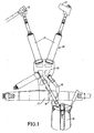
- the harness 10 comprises two straps 11 that can be placed on the shoulders of the operator.
- the straps are in one end secured to a stiff plate 12 placed on the back of the operator, while the other ends of the straps 11 are secured to a device 13 that consists of two parts, that can be secured to each other so that the two straps are connected on the chest of the operator.
- a third strap is running underneath one of the operator's arms and to the stiff plate 12 on the back of the operator.
- a hip pad 15 is hanging in a rope or a string 16 that is running between the device on the chest and the stiff plate 12 on the back of the operator.
- the hip pad 15 is movable along the rope 16 or string that has an adjustable length so that the position of the hip pad 15 can be optimised for the operator and the tool that is used.
- a waist belt 17 is also attached to the stiff plate 12 on the back of the operator in order to reduce the loads on the shoulders and the back of the operator.
- the tool is attached to a hook placed on the hip pad 15 so that the weight of the tool is carried by the harness 10.
- the hip pad 15 is also secured to the harness 10 by an elastic or non-elastic relief strap 19 that is running between the hip pad 15 and the stiff plate 12 on the back of the operator.
- This elastic or non-elastic strap 19 rearranges the loads on the operator so that the waist belt 17 instead of the shoulders carries the more of the tool weight.
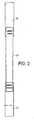
- the elastic or non-elastic strap 19 is preferably made of an elastic material that reduces movements in the tool so that the comfort for the operator is improved.
- the relief strap 19 can be designed in different ways.
- One solution is to use an elastic material for a midsection 20 of the strap 19 and a more non-elastic material 21 in the ends to make it easier to secure the strap to the hip pad 15 and the stiff plate 12 on the back of the operator.
Landscapes
- Harvester Elements (AREA)
- Workshop Equipment, Work Benches, Supports, Or Storage Means (AREA)
- Orthopedics, Nursing, And Contraception (AREA)
Abstract
Description
- Engine powered tools like for example clearing saws, trimmers and brush cutters are widely used for work in forests and gardens. The different types of tools are available in different sizes that are developed to meet the requirements for the work. The operator often works long shifts with the tool and the body of the operator will therefore be exposed to big loads.
- In order to improve the working conditions for the operator these tools are carried in a harness placed on the back, shoulders and hip of the operator. The tool is attached to the harness by a hook placed on a hip pad that is hanging down from the harness in a rope. The hip pad is during use placed close to one of the hips of the operator. The use of a harness for carrying the tool reduces the loads on the arms of the operator since most of the tool weight is carried by the back and the shoulders of the operator instead of the operator's arms that are used for the control of the tool. The hip pad is used to reduce the wear from the hook that is connected to the tool and to support the tool on the hip of the operator. The position of the hip pad is adjustable in order to suite operators with different length. The straps on the harness are also adjustable to be comfortable for the operator to wear.
- The harnesses available on the market today are designed to meet the requirements in laws that regulate these kinds of tools in order to guarantee the safety of the operator. These harnesses are designed so that the operator can open the harness by one single handle that should be placed so that it is easy for the operator to reach when the harness is in its right position on the operator. This means that when the operator opens the harness it will fall off the shoulders of the operator and down to the ground so that the operator gets free from the tool. A harness designed like this however has the drawback that it is very difficult to make it comfortable for the operator to wear.
- New laws, though, replace the laws that the known harnesses are designed to meet. According to the new laws it must be possible to release the tool from the operator in an easy way instead of the tool and the harness like the previous laws stated. This means that the operator must be able to release the tool from the harness very quickly and by using only one hand. If the release mechanism is moved to the hook on the hip pad that the tool is attached to the harness can be designed to suite the operator as good as possible. The new type of harnesses is therefore more ergonomic and reduces the loads on the operator.
- The known models of harnesses have two straps that are placed over the shoulders of the operator like the straps on a rucksack. One end of the straps are secured to a plate placed on the back of the operator and the other end is secured to a device, placed on the chest of the operator, that can be opened so that the straps are released from the device. Further, there is a third strap running between the plate on the back of the operator and the device on the chest of the operator. This strap is placed on the opposite side of the operator as the tool and is running underneath the operator's arm. On the tool side of the operator the hip pad is hanging in a rope with adjustable length secured in one end to the plate on the back of the operator and the other end to the device on the chest of the operator. Since the length of the rope can be adjusted it is possible for the operator to alternate the height of the hip pad and consequently the tool that is attached to the hip pad. This makes it possible for different operators to select a suitable height for the tool. The device on the chest of the operator can be opened so that the two shoulder straps are released from the device to let the harness and the tool drop to the ground if there are problems with the tool that could affect the safety of the operator. To make this arrangement work properly the hip pad can only be hanging in a rope or a strap, which means that the biggest part of the tool weight is carried by the shoulders of the operator. This means that the use of such a harness will be very tiring for the shoulders and back of the operator.
- An example of this known type of harness is disclosed in
EP0826324 A2 . - The harness according to the invention has a more advanced design than the harness iescribed above. The design of the known harnesses has though been the framework or the new harness that is provided with several details.
- The claimed harness has a plate arranged to be placed on the back of an operator, at least two straps secured at a first end to the plate and arranged to pass over the shoulders of the operator, a device, which is arranged to be secured at a second end of the straps such that the straps can be connected on the chest of the operator, a waist belt secured to the plate, a string or a rope running between the plate and the device, and a hip pad hanging on the string or rope and being slidably movable along the string or rope, wherein the hip pad is secured to the plate on the back of the operator by a relief strap.
- Since the hip pad is secured to the plate by a strap, the hip pad is pulled towards the operator and some of the weight is moved over from the rope to the waist belt compared to earlier designs. This means that the load on the shoulders and the back is reduced, which gives a more ergonomic harness.
- One embodiment of the claimed invention is illustrated in the drawings.
- Figure 1.
- Illustrates the harness.
- Figure 2.
- Illustrates the elastic strap.
- In order to improve the situation for the operator trimmers and clearing saws are normally carried in a
harness 10. Theharness 10 comprises twostraps 11 that can be placed on the shoulders of the operator. The straps are in one end secured to astiff plate 12 placed on the back of the operator, while the other ends of thestraps 11 are secured to adevice 13 that consists of two parts, that can be secured to each other so that the two straps are connected on the chest of the operator. From the device 13 a third strap is running underneath one of the operator's arms and to thestiff plate 12 on the back of the operator. On the opposite side of the operator compared to the third strap ahip pad 15 is hanging in a rope or astring 16 that is running between the device on the chest and thestiff plate 12 on the back of the operator. Thehip pad 15 is movable along therope 16 or string that has an adjustable length so that the position of thehip pad 15 can be optimised for the operator and the tool that is used. Awaist belt 17 is also attached to thestiff plate 12 on the back of the operator in order to reduce the loads on the shoulders and the back of the operator. - The tool is attached to a hook placed on the
hip pad 15 so that the weight of the tool is carried by theharness 10. To reduce the weight carried by the shoulders and the back of the operator thehip pad 15 is also secured to theharness 10 by an elastic ornon-elastic relief strap 19 that is running between thehip pad 15 and thestiff plate 12 on the back of the operator. This elastic ornon-elastic strap 19 rearranges the loads on the operator so that thewaist belt 17 instead of the shoulders carries the more of the tool weight. The elastic ornon-elastic strap 19 is preferably made of an elastic material that reduces movements in the tool so that the comfort for the operator is improved. - The
relief strap 19 can be designed in different ways. One solution is to use an elastic material for amidsection 20 of thestrap 19 and a morenon-elastic material 21 in the ends to make it easier to secure the strap to thehip pad 15 and thestiff plate 12 on the back of the operator.
Claims (4)
- A carrier device for a portable tool, the carrier device comprising:- a plate (12) arranged to be placed on the back of an operator,- at least two straps (11), which are secured at a first end to the plate (12) and arranged to pass over the shoulders of the operator,- a device (13), for securing a second end of the straps (11) such that the straps can be connected on the chest of the operator,- a waist belt (17) secured to the plate (12),- a string or a rope (16) running between the plate (12) and the device (13), and- a hip pad (15) hanging on the string or rope (16) and being movable along the string or rope (16),characterised in that the hip pad (15) is secured to the plate (12) on the back of the operator by a relief strap (19) for reducing the load on the shoulders and the back.
- A carrier device according to claim 1, characterised in that the relief strap (19) is running from the hip pad (15) and behind the back of the operator.
- A carrier device according to claim 1 or 2, characterised in that the relief strap (19) is secured to the hip pad (15) and / or the plate (12) in such a way that the length of the relief strap (19) can be adjusted.
- A carrier device according to any of the previous claims, characterised in that the relief strap (19) is secured in the top section of the hip pad (15).
Applications Claiming Priority (3)
| Application Number | Priority Date | Filing Date | Title |
|---|---|---|---|
| SE0101921A SE519076C2 (en) | 2001-05-31 | 2001-05-31 | Device by a hand harness for hand tools |
| SE0101921 | 2001-05-31 | ||
| PCT/SE2002/001057 WO2002096238A1 (en) | 2001-05-31 | 2002-05-30 | Carrier device for an engine powered tool |
Publications (2)
| Publication Number | Publication Date |
|---|---|
| EP1443836A1 EP1443836A1 (en) | 2004-08-11 |
| EP1443836B1 true EP1443836B1 (en) | 2011-07-20 |
Family
ID=20284310
Family Applications (1)
| Application Number | Title | Priority Date | Filing Date |
|---|---|---|---|
| EP02736384A Expired - Lifetime EP1443836B1 (en) | 2001-05-31 | 2002-05-30 | Carrier device for an engine powered tool |
Country Status (6)
| Country | Link |
|---|---|
| US (1) | US7163132B2 (en) |
| EP (1) | EP1443836B1 (en) |
| CN (1) | CN1244304C (en) |
| AT (1) | ATE516723T1 (en) |
| SE (1) | SE519076C2 (en) |
| WO (1) | WO2002096238A1 (en) |
Cited By (1)
| Publication number | Priority date | Publication date | Assignee | Title |
|---|---|---|---|---|
| US11466813B2 (en) | 2018-12-03 | 2022-10-11 | Globe (jiangsu) Co., Ltd. | Tool carrier |
Families Citing this family (21)
| Publication number | Priority date | Publication date | Assignee | Title |
|---|---|---|---|---|
| WO2008079058A1 (en) * | 2006-12-27 | 2008-07-03 | Husqvarna Aktiebolag | Harness for a hand-held working tool with a secon attachment element |
| WO2008147257A1 (en) * | 2007-06-01 | 2008-12-04 | Husqvarna Aktibeloag | Harness and chest plate therein |
| EP2155014A4 (en) * | 2007-06-01 | 2015-05-27 | Husqvarna Ab | BELT FOR ELECTRIC TOOL WITH ROD |
| US20090242598A1 (en) * | 2008-03-31 | 2009-10-01 | Brent Ronald Dormaar | Portable hand tool carrier harness |
| EP2243347B1 (en) * | 2009-04-24 | 2012-01-04 | Makita Corporation | Harness for a handheld power equipment |
| US8477610B2 (en) * | 2010-05-31 | 2013-07-02 | Microsoft Corporation | Applying policies to schedule network bandwidth among virtual machines |
| WO2012050566A1 (en) * | 2010-10-12 | 2012-04-19 | Utc Fire & Security Corporation | Fire extinguisher harness |
| GB2488807B (en) * | 2011-03-09 | 2013-02-06 | Steven Paul Ellis | The Lopper Mate |
| JP2014516287A (en) * | 2011-04-01 | 2014-07-10 | ストロング アーム テクノロジーズ,インコーポレイティド | Automatic actuated posture adaptation lifting support device |
| JP5722750B2 (en) * | 2011-11-11 | 2015-05-27 | 株式会社マキタ | Harness |
| JP5788768B2 (en) * | 2011-11-11 | 2015-10-07 | 株式会社マキタ | Harness |
| JP5960484B2 (en) * | 2012-04-19 | 2016-08-02 | 株式会社やまびこ | Shoulder harness for portable work machines |
| AU2013204737A1 (en) * | 2012-05-09 | 2013-11-28 | Minelab Electronics Pty Limited | A support arrangement for an implement |
| US9457822B2 (en) | 2013-02-02 | 2016-10-04 | Kohler Co. | Portable generators |
| US9427069B1 (en) | 2015-06-22 | 2016-08-30 | Atlas 46, Llc | Drill holster |
| US10051948B2 (en) | 2015-09-04 | 2018-08-21 | Atlas 46, Llc | Utility belt |
| US10548389B1 (en) * | 2018-07-31 | 2020-02-04 | Jose Luis Santana-Zaizar | Backpack system |
| EP3685655B1 (en) * | 2018-11-30 | 2022-01-19 | Honda Motor Co., Ltd. | Work machine pad |
| CN111511192A (en) * | 2018-11-30 | 2020-08-07 | 本田技研工业株式会社 | Support structure for work machine pads |
| JP6757859B1 (en) * | 2018-11-30 | 2020-09-23 | 本田技研工業株式会社 | Support belt for work equipment |
| SE546771C2 (en) * | 2022-10-12 | 2025-02-18 | Husqvarna Ab | Tool carrying harness and strap assembly for adjusting the same |
Family Cites Families (7)
| Publication number | Priority date | Publication date | Assignee | Title |
|---|---|---|---|---|
| US119400A (en) * | 1871-09-26 | Improvement in military equipments | ||
| SE458820B (en) * | 1986-05-12 | 1989-05-16 | Panth Produkter Ab | DEVICE FOR ROYAL SHADE |
| SE500322C2 (en) * | 1992-10-29 | 1994-06-06 | Panth Produkter Ab | Device for cleaning saw harness |
| DE19634670C2 (en) * | 1996-08-28 | 1998-12-03 | Stihl Maschf Andreas | Belt arrangement for carrying a hand-held implement |
| US5915606A (en) * | 1997-12-08 | 1999-06-29 | Jensen; Niels C. | Container carrier |
| SE510518C2 (en) * | 1998-06-03 | 1999-05-31 | Electrolux Ab | Carrier for a motor-driven work tool |
| US6345751B1 (en) * | 2000-08-04 | 2002-02-12 | Robert Nolan Elliot | Method and apparatus for carrying a portable electronic device |
-
2001
- 2001-05-31 SE SE0101921A patent/SE519076C2/en unknown
-
2002
- 2002-05-30 EP EP02736384A patent/EP1443836B1/en not_active Expired - Lifetime
- 2002-05-30 US US10/485,238 patent/US7163132B2/en not_active Expired - Lifetime
- 2002-05-30 WO PCT/SE2002/001057 patent/WO2002096238A1/en not_active Ceased
- 2002-05-30 CN CNB028151305A patent/CN1244304C/en not_active Expired - Lifetime
- 2002-05-30 AT AT02736384T patent/ATE516723T1/en not_active IP Right Cessation
Cited By (1)
| Publication number | Priority date | Publication date | Assignee | Title |
|---|---|---|---|---|
| US11466813B2 (en) | 2018-12-03 | 2022-10-11 | Globe (jiangsu) Co., Ltd. | Tool carrier |
Also Published As
| Publication number | Publication date |
|---|---|
| WO2002096238A1 (en) | 2002-12-05 |
| CN1536969A (en) | 2004-10-13 |
| ATE516723T1 (en) | 2011-08-15 |
| EP1443836A1 (en) | 2004-08-11 |
| SE0101921D0 (en) | 2001-05-31 |
| SE0101921L (en) | 2002-12-01 |
| SE519076C2 (en) | 2003-01-07 |
| US7163132B2 (en) | 2007-01-16 |
| US20050000994A1 (en) | 2005-01-06 |
| CN1244304C (en) | 2006-03-08 |
Similar Documents
| Publication | Publication Date | Title |
|---|---|---|
| US7163132B2 (en) | Carrier device for an engine powered tool | |
| US6247624B1 (en) | Carrier device for a power-driven work tool | |
| US4962873A (en) | Materials handling device | |
| CN1108742C (en) | Belt arrangement for carrying a hand-held power tool | |
| US4179805A (en) | Portable power operated tool | |
| US5716087A (en) | Ergonomic scoop assembly | |
| US20020145027A1 (en) | Low slung tool carrier | |
| US4537339A (en) | Umbrella support | |
| EP2437587B1 (en) | Clearing saw | |
| KR101480826B1 (en) | Electric pruning shears | |
| EP2155015A1 (en) | Back plate for a harness | |
| EP2152119B1 (en) | Harness and chest plate therein | |
| US20020166241A1 (en) | Portable counterbalancing system for handheld implements | |
| CN118613150B (en) | Lawn mower belts and lawn mower kits | |
| GB2266682B (en) | Power tool extension attachment | |
| KR101931279B1 (en) | Waist belt | |
| EP2094127B1 (en) | Harness with an arrangement for carrying a hand-held motor-driven tool | |
| AU2006222724A1 (en) | Backpack device for carrying an electrical hand tool | |
| WO2008076009A1 (en) | Arrangement for carrying a hand-held motor-driven tool on a harness | |
| EP2240046B1 (en) | Supporting device for portable agricultural machinery, particularly for blowers, tree shakers and similar machinery | |
| SE0300849D0 (en) | Harness for a blower | |
| CN209579538U (en) | Wearable Assisted Human Handling Devices | |
| US20050067448A1 (en) | Hook for attaching a portable tool to a carrying device | |
| CN216087672U (en) | Laborsaving brush cutter of diversion | |
| WO2025151058A1 (en) | Outdoor power tool harness |
Legal Events
| Date | Code | Title | Description |
|---|---|---|---|
| PUAI | Public reference made under article 153(3) epc to a published international application that has entered the european phase |
Free format text: ORIGINAL CODE: 0009012 |
|
| 17P | Request for examination filed |
Effective date: 20040203 |
|
| AK | Designated contracting states |
Kind code of ref document: A1 Designated state(s): AT BE CH CY DE DK ES FI FR GB GR IE IT LI LU MC NL PT SE TR |
|
| AX | Request for extension of the european patent |
Extension state: AL LT LV MK RO SI |
|
| RAP1 | Party data changed (applicant data changed or rights of an application transferred) |
Owner name: HUSQVARNA AB |
|
| 17Q | First examination report despatched |
Effective date: 20100818 |
|
| GRAP | Despatch of communication of intention to grant a patent |
Free format text: ORIGINAL CODE: EPIDOSNIGR1 |
|
| GRAS | Grant fee paid |
Free format text: ORIGINAL CODE: EPIDOSNIGR3 |
|
| GRAA | (expected) grant |
Free format text: ORIGINAL CODE: 0009210 |
|
| AK | Designated contracting states |
Kind code of ref document: B1 Designated state(s): AT BE CH CY DE DK ES FI FR GB GR IE IT LI LU MC NL PT SE TR |
|
| REG | Reference to a national code |
Ref country code: GB Ref legal event code: FG4D |
|
| REG | Reference to a national code |
Ref country code: CH Ref legal event code: EP |
|
| REG | Reference to a national code |
Ref country code: DE Ref legal event code: R096 Ref document number: 60240555 Country of ref document: DE Effective date: 20110908 |
|
| REG | Reference to a national code |
Ref country code: SE Ref legal event code: TRGR |
|
| REG | Reference to a national code |
Ref country code: NL Ref legal event code: VDEP Effective date: 20110720 |
|
| REG | Reference to a national code |
Ref country code: AT Ref legal event code: MK05 Ref document number: 516723 Country of ref document: AT Kind code of ref document: T Effective date: 20110720 |
|
| PG25 | Lapsed in a contracting state [announced via postgrant information from national office to epo] |
Ref country code: BE Free format text: LAPSE BECAUSE OF FAILURE TO SUBMIT A TRANSLATION OF THE DESCRIPTION OR TO PAY THE FEE WITHIN THE PRESCRIBED TIME-LIMIT Effective date: 20110720 Ref country code: PT Free format text: LAPSE BECAUSE OF FAILURE TO SUBMIT A TRANSLATION OF THE DESCRIPTION OR TO PAY THE FEE WITHIN THE PRESCRIBED TIME-LIMIT Effective date: 20111121 Ref country code: NL Free format text: LAPSE BECAUSE OF FAILURE TO SUBMIT A TRANSLATION OF THE DESCRIPTION OR TO PAY THE FEE WITHIN THE PRESCRIBED TIME-LIMIT Effective date: 20110720 |
|
| PG25 | Lapsed in a contracting state [announced via postgrant information from national office to epo] |
Ref country code: CY Free format text: LAPSE BECAUSE OF FAILURE TO SUBMIT A TRANSLATION OF THE DESCRIPTION OR TO PAY THE FEE WITHIN THE PRESCRIBED TIME-LIMIT Effective date: 20110720 Ref country code: AT Free format text: LAPSE BECAUSE OF FAILURE TO SUBMIT A TRANSLATION OF THE DESCRIPTION OR TO PAY THE FEE WITHIN THE PRESCRIBED TIME-LIMIT Effective date: 20110720 Ref country code: GR Free format text: LAPSE BECAUSE OF FAILURE TO SUBMIT A TRANSLATION OF THE DESCRIPTION OR TO PAY THE FEE WITHIN THE PRESCRIBED TIME-LIMIT Effective date: 20111021 |
|
| PLBE | No opposition filed within time limit |
Free format text: ORIGINAL CODE: 0009261 |
|
| STAA | Information on the status of an ep patent application or granted ep patent |
Free format text: STATUS: NO OPPOSITION FILED WITHIN TIME LIMIT |
|
| PG25 | Lapsed in a contracting state [announced via postgrant information from national office to epo] |
Ref country code: IT Free format text: LAPSE BECAUSE OF FAILURE TO SUBMIT A TRANSLATION OF THE DESCRIPTION OR TO PAY THE FEE WITHIN THE PRESCRIBED TIME-LIMIT Effective date: 20110720 |
|
| 26N | No opposition filed |
Effective date: 20120423 |
|
| PG25 | Lapsed in a contracting state [announced via postgrant information from national office to epo] |
Ref country code: DK Free format text: LAPSE BECAUSE OF FAILURE TO SUBMIT A TRANSLATION OF THE DESCRIPTION OR TO PAY THE FEE WITHIN THE PRESCRIBED TIME-LIMIT Effective date: 20110720 |
|
| REG | Reference to a national code |
Ref country code: DE Ref legal event code: R097 Ref document number: 60240555 Country of ref document: DE Effective date: 20120423 |
|
| PG25 | Lapsed in a contracting state [announced via postgrant information from national office to epo] |
Ref country code: MC Free format text: LAPSE BECAUSE OF NON-PAYMENT OF DUE FEES Effective date: 20120531 |
|
| REG | Reference to a national code |
Ref country code: CH Ref legal event code: PL |
|
| PG25 | Lapsed in a contracting state [announced via postgrant information from national office to epo] |
Ref country code: LI Free format text: LAPSE BECAUSE OF NON-PAYMENT OF DUE FEES Effective date: 20120531 Ref country code: CH Free format text: LAPSE BECAUSE OF NON-PAYMENT OF DUE FEES Effective date: 20120531 |
|
| REG | Reference to a national code |
Ref country code: IE Ref legal event code: MM4A |
|
| PG25 | Lapsed in a contracting state [announced via postgrant information from national office to epo] |
Ref country code: ES Free format text: LAPSE BECAUSE OF FAILURE TO SUBMIT A TRANSLATION OF THE DESCRIPTION OR TO PAY THE FEE WITHIN THE PRESCRIBED TIME-LIMIT Effective date: 20111031 Ref country code: IE Free format text: LAPSE BECAUSE OF NON-PAYMENT OF DUE FEES Effective date: 20120530 |
|
| PG25 | Lapsed in a contracting state [announced via postgrant information from national office to epo] |
Ref country code: TR Free format text: LAPSE BECAUSE OF FAILURE TO SUBMIT A TRANSLATION OF THE DESCRIPTION OR TO PAY THE FEE WITHIN THE PRESCRIBED TIME-LIMIT Effective date: 20110720 |
|
| PG25 | Lapsed in a contracting state [announced via postgrant information from national office to epo] |
Ref country code: LU Free format text: LAPSE BECAUSE OF NON-PAYMENT OF DUE FEES Effective date: 20120530 |
|
| REG | Reference to a national code |
Ref country code: FR Ref legal event code: PLFP Year of fee payment: 15 |
|
| REG | Reference to a national code |
Ref country code: FR Ref legal event code: PLFP Year of fee payment: 16 |
|
| REG | Reference to a national code |
Ref country code: FR Ref legal event code: PLFP Year of fee payment: 17 |
|
| PGFP | Annual fee paid to national office [announced via postgrant information from national office to epo] |
Ref country code: DE Payment date: 20180502 Year of fee payment: 17 Ref country code: FI Payment date: 20180423 Year of fee payment: 17 |
|
| PGFP | Annual fee paid to national office [announced via postgrant information from national office to epo] |
Ref country code: GB Payment date: 20180503 Year of fee payment: 17 |
|
| REG | Reference to a national code |
Ref country code: DE Ref legal event code: R119 Ref document number: 60240555 Country of ref document: DE |
|
| GBPC | Gb: european patent ceased through non-payment of renewal fee |
Effective date: 20190530 |
|
| PG25 | Lapsed in a contracting state [announced via postgrant information from national office to epo] |
Ref country code: FI Free format text: LAPSE BECAUSE OF NON-PAYMENT OF DUE FEES Effective date: 20190530 |
|
| PG25 | Lapsed in a contracting state [announced via postgrant information from national office to epo] |
Ref country code: GB Free format text: LAPSE BECAUSE OF NON-PAYMENT OF DUE FEES Effective date: 20190530 Ref country code: DE Free format text: LAPSE BECAUSE OF NON-PAYMENT OF DUE FEES Effective date: 20191203 |
|
| PGFP | Annual fee paid to national office [announced via postgrant information from national office to epo] |
Ref country code: FR Payment date: 20210408 Year of fee payment: 20 |
|
| PGFP | Annual fee paid to national office [announced via postgrant information from national office to epo] |
Ref country code: SE Payment date: 20210413 Year of fee payment: 20 |