EP1443688A2 - Optical heterodyne receiver - Google Patents
Optical heterodyne receiver Download PDFInfo
- Publication number
- EP1443688A2 EP1443688A2 EP03021207A EP03021207A EP1443688A2 EP 1443688 A2 EP1443688 A2 EP 1443688A2 EP 03021207 A EP03021207 A EP 03021207A EP 03021207 A EP03021207 A EP 03021207A EP 1443688 A2 EP1443688 A2 EP 1443688A2
- Authority
- EP
- European Patent Office
- Prior art keywords
- polarization
- receiver
- receivers
- optical source
- lightwave
- Prior art date
- Legal status (The legal status is an assumption and is not a legal conclusion. Google has not performed a legal analysis and makes no representation as to the accuracy of the status listed.)
- Withdrawn
Links
Images



Classifications
-
- H—ELECTRICITY
- H04—ELECTRIC COMMUNICATION TECHNIQUE
- H04B—TRANSMISSION
- H04B10/00—Transmission systems employing electromagnetic waves other than radio-waves, e.g. infrared, visible or ultraviolet light, or employing corpuscular radiation, e.g. quantum communication
- H04B10/07—Arrangements for monitoring or testing transmission systems; Arrangements for fault measurement of transmission systems
-
- G—PHYSICS
- G01—MEASURING; TESTING
- G01J—MEASUREMENT OF INTENSITY, VELOCITY, SPECTRAL CONTENT, POLARISATION, PHASE OR PULSE CHARACTERISTICS OF INFRARED, VISIBLE OR ULTRAVIOLET LIGHT; COLORIMETRY; RADIATION PYROMETRY
- G01J4/00—Measuring polarisation of light
- G01J4/04—Polarimeters using electric detection means
Definitions
- the polarization state of a lightwave may be determined by detecting the optical power transmitted through specific polarization filters.
- Conventional polarimeters typically measure the optical powers P 0 - P 3 to determine the Stokes parameters S 0 - S 3 .
- FIG.1a shows conventional space-division polarimeter 100 where the lightwave on input 101 is split into four separate lightwaves and the resulting lightwaves are processed in parallel.
- the lightwave on output 102 passes through linear horizontal polarizer 115 and provides P 1 .
- the lightwave on output 103 passes through linear 45 degree polarizer 120 and provides P 2 .
- the lightwave on output 104 passes through quarter-wave plate 125 and linear 45 degree polarizer to provide P 3 which is a measure of circularly polarized light.
- Quarter-wave plate 125 transforms the circularly polarized portion of the input lightwave to a linear 45 degree lightwave which is passed through linear 45 degree polarizer 130.
- the lightwave on output 105 passes out directly to provide P 0 , which is proportional to the total power.
- the degree of polarization is determinable from measurements performed by polarimeter 100 using equations (1)-(5).
- Some heterodyne optical receivers such as the Agilent Technologies 81910A and 83453A, may be configured to measure the polarization of the received optical field.
- the phase difference between two electrical signals coming from the receiver must be measured to determine the polarization of the received optical field. This phase measurement can be difficult, in particular if the electrical signals contain significant noise. Additionally, the measurements from these heterodyne optical receivers do not allow a determination of the degree of polarization.
- it would be desirable to have a heterodyne optical receiving system which overcomes these difficulties and provides the data normally supplied by a conventional polarimeter.
- the polarization of the lightwave at the input to a heterodyne receiver can be determined by measurements of the amplitude of electrical signals without the need for phase measurements. This allows more accurate measurements of the polarization in the presence of noise and allows a determination of the degree of polarization of the lightwave. All of the polarization resolving receivers may be balanced receivers to reduce the intensity noise.
- FIG. 1b shows the concept of a polarization-resolving heterodyne receiver in accordance with the invention.
- Swept local oscillator reference source 175 provides a reference signal proportional to cos ⁇ 1 t having a definite linear polarization while the input signal is proportional to x(t)cos ⁇ 2 t with an unknown polarization.
- the typically radio frequency output from receiver 185 is proportional to 2 x(t)cos ⁇ cos( ⁇ 1 - ⁇ 2 )t where ⁇ is the angle between the signal input and the reference signal polarization.
- the amplitude of the signal detected by receiver 185 is proportional to 2 x(t)cos ⁇ which is equivalent to the output of an input signal passed through a polarizer positioned at an angle ⁇ to the polarization of the input signal.
- a polarization synthesizer or waveplate may be placed in the signal path or in the local oscillator path as shown in FIGs. 2a and 2b, respectively.
- the two situations may be examined using a Jones matrix analysis.
- Case 1 shown in simplified form in FIG. 2a assumes polarization synthesizer 201 or waveplate 201 is in signal path 205.
- Case 2 shown in simplified form in FIG. 2b assumes polarization synthesizer 201 or waveplate 201 is in local oscillator path 206.
- Coupler 207 combines signal path 205 and local oscillator path 206.
- FIG. 3 shows an embodiment in accordance with the invention.
- swept narrow linewidth optical source 310 is used to provide the swept local oscillator reference source needed for a heterodyne system.
- Optical source 310 connects to polarizer 320 by single mode optical fiber 315.
- Polarizer 320 connects to four way splitter 335 by polarization maintaining optical fiber 325.
- Four way splitter 335 splits the reference lightwave four ways into polarization maintaining fibers 345, 346, 347 and 348.
- Polarization maintaining fibers 345, 346, 347 and 348 connect four way splitter 335 to single polarization receiver 360, single polarization receiver 365, single polarization receiver 370 and polarization diversity receiver 375, respectively.
- An input signal lightwave enters four way splitter 340 on single mode optical fiber 330 and the signal lightwave is split four ways into single mode fibers 351, 352, 353 and 354.
- Single mode fiber 353 couples through quarter waveplate 355 .
- Single mode fibers 351, 352, 353 and 354 are also connected to single polarization receiver 360, single polarization receiver 365, single polarization receiver 370 and polarization diversity receiver 375, respectively, as shown in FIG. 3. Note that receivers 360, 365, 370 and 375 may be balanced receivers to reduce intensity noise.
- Polarizer 320 receives the reference lightwave from optical source 310 and ensures that the reference lightwave entering polarization maintaining optical fiber 325 is linearly polarized and is properly aligned with the polarization direction of polarization maintaining optical fiber 325.
- Polarization of the reference lightwave is maintained after splitting by four way splitter 335 into polarization maintaining optical fibers 345, 346, 347 and 348.
- Polarization maintaining optical fiber 345 is typically oriented such that the linear polarization of the reference lightwave entering single polarization receiver 360 is 0 degrees.
- Polarization maintaining optical fiber 346 is typically oriented such that the linear polarization of the reference lightwave entering single polarization receiver 365 is 45 degrees.
- Polarization maintaining optical fiber 347 is typically oriented such that the linear polarization of the reference lightwave entering single polarization receiver 370 is 45 degrees.
- Quarter wave retarder 355 converts the circularly polarized part of the signal lightwave entering single polarization receiver 370 on single mode optical fiber 353 into 45 degree linearly polarized light prior to reception by single polarization receiver 370.
- the polarization of the signal lightwave entering single polarization receiver 370 is 45 degrees.
- Single polarization receivers 360, 365 and 370 function as polarization sensitive optical heterodyne receivers that convert the input lightwaves into electrical representations.
- the electrical signal output is related to the intensity of the component of the input signal lightwave polarized in the direction of the reference lightwave. Therefore, the electrical output of single polarization receivers 360, 365 and 370 provides measurements of P 1 , P 2 and P 3 , respectively.
- Polarization diversity receiver 375 functions as a coherent receiver that converts the input lightwaves into electrical representations.
- the electrical signal output is related to the total intensity of the input signal lightwave. Therefore, the electrical output of polarization diversity receiver 375 provides a measurement of P 0 .
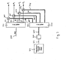
- FIG. 4 shows an embodiment in accordance with the invention.
- Swept narrow linewidth optical source 410 provides the swept local oscillator reference source needed for a heterodyne system.
- Optical source 410 connects to polarizer 420 by single mode optical fiber 415.
- Polarizer 420 connects to three way splitter 435 by polarization maintaining optical fiber 425.
- Three way splitter 435 splits the reference signal lightwave three ways into polarization maintaining fibers 445, 446 and 448.
- Polarization maintaining optical fibers 445 and 446 connect three way splitter 435 to polarization resolving receiver 480, single polarization receiver 465 and single polarization receiver 470, respectively.
- Polarization maintaining optical fiber 448 connects to single mode optical fiber 449 via quarter wave retarder 455.
- Single mode optical fiber 449 connects quarter wave retarder 455 to single polarization receiver 470.
- quarter wave retarder 455 may be placed in the input signal path between single mode fiber 453 and receiver 470.
- An input signal lightwave enters three way splitter 440 on single mode optical fiber 430 and the signal lightwave is split three ways into single mode fibers 451, 452 and 453.
- Single mode fibers 451, 452 and 453 are also connected to polarization resolving receiver 480, single polarization receiver 465 and single polarization receiver 470. Note that receivers 480, 465 and 470 may be balanced receivers to reduce intensity noise.
- Polarizer 420 receives the reference lightwave from optical source 410 and ensures that the reference lightwave entering polarization maintaining optical fiber 425 is linearly polarized and is properly aligned with the polarization direction of polarization maintaining optical fiber 425.
- Polarization of the reference lightwave is maintained after splitting by three way splitter 435 into polarization maintaining optical fibers 445, 446 and 448.
- Polarization maintaining optical fiber 445 is oriented such that the linear polarization of the reference lightwave entering polarization resolving receiver 480 is 45 degrees.
- Polarization maintaining optical fiber 446 is oriented such that the linear polarization of the reference lightwave entering single polarization receiver 465 is 45 degrees.
- Polarization maintaining optical fiber 448 is connected to quarter wave retarder 455.
- Quarter wave retarder 455 converts the linearly polarized reference lightwave coming from polarization maintaining optical fiber 448 to circularly polarized light that passes to single polarization receiver 470 on single mode optical fiber 449.
- Single polarization receivers 465 and 470 function as polarization sensitive optical heterodyne receivers that convert the input lightwaves into electrical representations.
- the electrical signal output is related to the intensity of the component of the input signal lightwave polarized in the direction of the reference lightwave.
- the electrical output of single polarization receivers 465 and 470 corresponds to P 2 and P 3 , respectively, and provides measurements of P 2 and P 3 .
- Polarization resolving receiver 480 provides two outputs x and y proportional to the input lightwave polarized in the x direction and the input lightwave polarized in the y direction.
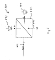
- FIG. 5 shows an embodiment in accordance with the invention of polarization resolving receiver 480 of FIG. 4.
- Polarizing beam splitter 530 splits the incoming lightwave from swept narrow linewidth optical source 410 which has a 45 degree polarization into two equal components that mix with the input lightwave from single mode fiber 451.
- the input signal is polarized with an unknown angle ⁇ with respect to polarizing beam splitter 530 and is split as cos ⁇ (x direction) and sin ⁇ (y direction).
- the reference lightwave from swept narrow linewidth optical source 410 is polarized at 45 degrees, the reference lightwave is equally divided between photodetectors 545 and 550. Squaring and summing the electrical output from photodetectors 545 and 550 in digital processor 499 produces a signal that is independent of the unknown angle ⁇ and taking the square root gives total power P 0 .
- the signal in the x direction is proportional to the power in the 0 degree polarization direction and is scaled to P 1 by scaler 490. Determining P 0 , P 1 , P 2 and P 3 allows calculation of the Stokes parameters and characterization of the degree of polarization of the input signal.
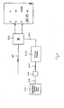
- FIG. 6 shows an embodiment in accordance with the invention using polarization synthesizer 630.
- the embodiment shown in FIG. 6 reduces the number of receivers required to one by introducing polarization synthesizer 630.
- Swept narrow line width optical source 610 is coupled to polarizer 620 by single mode fiber 615.
- Polarizer 620 is coupled to polarization synthesizer 630 by polarization maintaining fiber 605.
- polarization maintaining fiber 605 typically, for the output of a polarization synthesizer to be known and well-defined, it is necessary to have a well-defined input polarization which is accomplished by using polarization maintaining fiber 605 to couple polarizer 620 to polarization synthesizer 630.
- Polarization synthesizer 630 is coupled to polarization resolving receiver 660 via single mode fiber 640.
- Polarization resolving receiver 660 is similar to polarization resolving receiver 480 shown in FIG. 5 and has an x and y component output.
- Polarization resolving receiver 660 is typically a balanced receiver.
- Polarization resolving receiver 660 is also coupled to receive input signal 651.
- Polarization resolving receiver 660 functions as a coherent receiver that converts the input lightwaves into electrical representations.
Landscapes
- Physics & Mathematics (AREA)
- Electromagnetism (AREA)
- Engineering & Computer Science (AREA)
- Computer Networks & Wireless Communication (AREA)
- Signal Processing (AREA)
- General Physics & Mathematics (AREA)
- Spectroscopy & Molecular Physics (AREA)
- Optical Communication System (AREA)
Abstract
Description
Claims (16)
- A polarization resolving heterodyne receiver apparatus comprising:an optical source (610);a polarization synthesizer (630) coupled to said optical source (610); anda polarization resolving receiver (660) coupled to said polarization synthesizer (630) and to an input signal line (651), said polarization resolving receiver (660) capable of outputting a signal related to the power in a polarization direction selected by said polarization synthesizer (630).
- The apparatus of Claim 1 wherein said optical source is a swept narrow line width optical source (610).
- The apparatus of Claim 1 or 2 wherein said optical source is coupled to said polarization synthesizer (630) using a polarization maintaining optical fiber (605).
- The apparatus of one of Claims 1 to 3 wherein said polarization synthesizer (630) is coupled to said polarization resolving receiver (660) using a single mode optical fiber (640).
- The apparatus of one of Claims 1 to 4 wherein said polarization direction is circular.
- The apparatus of one of Claims 1 to 5 wherein said polarization resolving receiver (660) is capable of outputting a first and second output signal.
- The apparatus of one of Claims 1 to 6 wherein a polarizer (620) is interposed between said optical source (610) and said polarization synthesizer (630).
- A polarization resolving heterodyne receiver apparatus comprising:an optical source (310, 410);a first splitter (335, 435) coupled to said optical source (310,410);a plurality of polarization receivers (360, 365, 370,375,480,465,470) coupled to said first splitter (335,435); anda second splitter (340, 440)coupled to said plurality of polarization receivers (360, 365, 370,375,480,465,470) and to an input signal line (330, 430), such that each of said plurality of polarization receivers (360, 365, 370,375,480,465,470) are operable to output an electrical signal proportional to an optical power.
- The apparatus of Claim 8 wherein said first splitter (335,435) is coupled to at least one of said plurality of polarization receivers (360,365,370,375,445,446) using a polarization maintaining optical fiber (345,346,347,348,445,446).
- The apparatus of Claim 8 or 9 wherein said optical source (310,410)is a swept narrow linewidth optical source.
- The apparatus of one of Claims 8 to 10 wherein a polarizer (320,420) is interposed between said optical source and said first splitter.
- The apparatus of one of Claims 8 to 11 wherein a waveplate (355) is interposed between said second splitter (340) and one of said plurality of polarization receivers (370).
- The apparatus of one of Claims 8 to 12 wherein one of said plurality of polarization receivers (480) is coupled to a scaler (490).
- The apparatus of one of Claims 8 to 13 wherein one of said plurality of polarization receivers (480) is capable of outputing a first and second output signal, said first output signal being proportional to the input lightwave polarized in the x direction and said second output signal being proportional to the input lightwave polarized in the y direction.
- The apparatus of one of Claims 8 to 14 wherein one of said plurality of polarization receivers is a polarization diversity receiver (375).
- The apparatus of one of Claims 8 to 15 wherein a waveplate (455) is interposed between said first splitter (435) and one of said plurality of polarization receivers (470).
Applications Claiming Priority (2)
| Application Number | Priority Date | Filing Date | Title |
|---|---|---|---|
| US355334 | 2003-01-31 | ||
| US10/355,334 US20060159452A1 (en) | 2003-01-31 | 2003-01-31 | Polarization resolving heterodyne optical receiver |
Publications (2)
| Publication Number | Publication Date |
|---|---|
| EP1443688A2 true EP1443688A2 (en) | 2004-08-04 |
| EP1443688A3 EP1443688A3 (en) | 2006-04-05 |
Family
ID=32655571
Family Applications (1)
| Application Number | Title | Priority Date | Filing Date |
|---|---|---|---|
| EP03021207A Withdrawn EP1443688A3 (en) | 2003-01-31 | 2003-09-18 | Optical heterodyne receiver |
Country Status (4)
| Country | Link |
|---|---|
| US (1) | US20060159452A1 (en) |
| EP (1) | EP1443688A3 (en) |
| JP (1) | JP2004233347A (en) |
| CN (1) | CN1519604A (en) |
Families Citing this family (1)
| Publication number | Priority date | Publication date | Assignee | Title |
|---|---|---|---|---|
| CN110945803B (en) * | 2017-07-25 | 2022-04-19 | 凯迪迪爱通信技术有限公司 | Optical receiver and coherent optical receiving method |
Family Cites Families (6)
| Publication number | Priority date | Publication date | Assignee | Title |
|---|---|---|---|---|
| US5102222A (en) * | 1990-02-08 | 1992-04-07 | Harmonic Lightwaves, Inc. | Light wave polarization determination using a hybrid system |
| US5227623A (en) * | 1992-01-31 | 1993-07-13 | Hewlett-Packard Company | Method and apparatus for measuring polarization mode dispersion in optical devices |
| WO1997002476A1 (en) * | 1995-06-30 | 1997-01-23 | Furukawa Denki Kogyo Kabushiki Kaisha | Method of evaluating and measuring polarization state, polarization state and polarization mode dispersion and apparatus therefor |
| US6535289B1 (en) * | 2000-06-02 | 2003-03-18 | Agilent Technologies, Inc. | System and method for optical heterodyne detection of an optical signal |
| US6563590B2 (en) * | 2001-02-16 | 2003-05-13 | Corning Incorporated | System and method for measurement of the state of polarization over wavelength |
| US6940594B2 (en) * | 2002-06-18 | 2005-09-06 | Agilent Technologies, Inc. | Measurement of polarization-resolved optical scattering parameters |
-
2003
- 2003-01-31 US US10/355,334 patent/US20060159452A1/en not_active Abandoned
- 2003-09-18 EP EP03021207A patent/EP1443688A3/en not_active Withdrawn
- 2003-10-30 CN CNA2003101030720A patent/CN1519604A/en active Pending
-
2004
- 2004-01-16 JP JP2004009302A patent/JP2004233347A/en active Pending
Also Published As
| Publication number | Publication date |
|---|---|
| US20060159452A1 (en) | 2006-07-20 |
| CN1519604A (en) | 2004-08-11 |
| JP2004233347A (en) | 2004-08-19 |
| EP1443688A3 (en) | 2006-04-05 |
Similar Documents
| Publication | Publication Date | Title |
|---|---|---|
| US7218436B2 (en) | Optical instrument and measurements using multiple tunable optical polarization rotators | |
| US7466471B2 (en) | Optical instrument and measurements using multiple tunable optical polarization rotators | |
| US5227623A (en) | Method and apparatus for measuring polarization mode dispersion in optical devices | |
| US5102222A (en) | Light wave polarization determination using a hybrid system | |
| US7889352B2 (en) | Integrated polarization beam splitter with quarter-wave plate for polarimeter and PMD compensation applications | |
| US5834933A (en) | Method for magnetooptic current measurement and magnetooptic current-measuring device | |
| EP1278087B1 (en) | Polarization diversity receiver with planar waveguide and polarizing beam splitter | |
| US11719598B2 (en) | Optical device for measuring power of test light and optical device testing method | |
| EP1231455A2 (en) | Method and system for optical spectrum analysis with a depolarized local oscillator signal | |
| US6856398B2 (en) | Method of and apparatus for making wavelength-resolved polarimetric measurements | |
| US6941081B2 (en) | Method and apparatus for polarization measurements | |
| JP2001281105A (en) | System and method for optical heterodyne detection of optical signals | |
| US6766115B1 (en) | Multiport optical component testing using a single optical receiver | |
| US7280770B2 (en) | Polarization diverse optical receiver using a polarization-dependent beam splitter | |
| US7095963B2 (en) | Multi-channel optical receiver for processing tri-cell polarization diversity detector outputs | |
| US6894780B2 (en) | Pilot tone multiplexing of polarization states in heterodyne optical component analysis | |
| JP2000131193A (en) | Optical module extinction ratio measurement device | |
| US6548801B1 (en) | System and method for optical heterodyne detection of an optical signal | |
| CA2351966A1 (en) | Method and apparatus for polarization measurements | |
| US20060159452A1 (en) | Polarization resolving heterodyne optical receiver | |
| US6850326B2 (en) | Determination of an optical parameter of an optical signal | |
| EP1207417B1 (en) | Polarization-corrected optical measuring unit | |
| US20030043467A1 (en) | Polarization delay unit | |
| JPH08278202A (en) | Polarization analysis optical system device and polarization analysis device using the same | |
| JP2002243585A (en) | Method and apparatus for determining characteristics of optical device |
Legal Events
| Date | Code | Title | Description |
|---|---|---|---|
| PUAI | Public reference made under article 153(3) epc to a published international application that has entered the european phase |
Free format text: ORIGINAL CODE: 0009012 |
|
| AK | Designated contracting states |
Kind code of ref document: A2 Designated state(s): AT BE BG CH CY CZ DE DK EE ES FI FR GB GR HU IE IT LI LU MC NL PT RO SE SI SK TR |
|
| AX | Request for extension of the european patent |
Extension state: AL LT LV MK |
|
| RIC1 | Information provided on ipc code assigned before grant |
Ipc: G01M 11/00 20060101ALI20051221BHEP Ipc: G01J 4/04 20060101ALI20051221BHEP Ipc: H04B 10/08 20060101AFI20051221BHEP |
|
| PUAL | Search report despatched |
Free format text: ORIGINAL CODE: 0009013 |
|
| AK | Designated contracting states |
Kind code of ref document: A3 Designated state(s): AT BE BG CH CY CZ DE DK EE ES FI FR GB GR HU IE IT LI LU MC NL PT RO SE SI SK TR |
|
| AX | Request for extension of the european patent |
Extension state: AL LT LV MK |
|
| 17P | Request for examination filed |
Effective date: 20060523 |
|
| 17Q | First examination report despatched |
Effective date: 20060714 |
|
| 17Q | First examination report despatched |
Effective date: 20060714 |
|
| AKX | Designation fees paid |
Designated state(s): DE FR GB |
|
| RAP1 | Party data changed (applicant data changed or rights of an application transferred) |
Owner name: AGILENT TECHNOLOGIES, INC. |
|
| STAA | Information on the status of an ep patent application or granted ep patent |
Free format text: STATUS: THE APPLICATION IS DEEMED TO BE WITHDRAWN |
|
| 18D | Application deemed to be withdrawn |
Effective date: 20071206 |