EP1443674A1 - Echo cancellation with double-talk detection - Google Patents
Echo cancellation with double-talk detection Download PDFInfo
- Publication number
- EP1443674A1 EP1443674A1 EP04250395A EP04250395A EP1443674A1 EP 1443674 A1 EP1443674 A1 EP 1443674A1 EP 04250395 A EP04250395 A EP 04250395A EP 04250395 A EP04250395 A EP 04250395A EP 1443674 A1 EP1443674 A1 EP 1443674A1
- Authority
- EP
- European Patent Office
- Prior art keywords
- echo
- echo signal
- signal
- mask
- power level
- Prior art date
- Legal status (The legal status is an assumption and is not a legal conclusion. Google has not performed a legal analysis and makes no representation as to the accuracy of the status listed.)
- Granted
Links
Images

Classifications
-
- H—ELECTRICITY
- H04—ELECTRIC COMMUNICATION TECHNIQUE
- H04M—TELEPHONIC COMMUNICATION
- H04M9/00—Arrangements for interconnection not involving centralised switching
- H04M9/08—Two-way loud-speaking telephone systems with means for conditioning the signal, e.g. for suppressing echoes for one or both directions of traffic
- H04M9/082—Two-way loud-speaking telephone systems with means for conditioning the signal, e.g. for suppressing echoes for one or both directions of traffic using echo cancellers
-
- H—ELECTRICITY
- H04—ELECTRIC COMMUNICATION TECHNIQUE
- H04B—TRANSMISSION
- H04B3/00—Line transmission systems
- H04B3/02—Details
- H04B3/20—Reducing echo effects or singing; Opening or closing transmitting path; Conditioning for transmission in one direction or the other
- H04B3/23—Reducing echo effects or singing; Opening or closing transmitting path; Conditioning for transmission in one direction or the other using a replica of transmitted signal in the time domain, e.g. echo cancellers
-
- H—ELECTRICITY
- H04—ELECTRIC COMMUNICATION TECHNIQUE
- H04B—TRANSMISSION
- H04B3/00—Line transmission systems
- H04B3/02—Details
- H04B3/20—Reducing echo effects or singing; Opening or closing transmitting path; Conditioning for transmission in one direction or the other
- H04B3/23—Reducing echo effects or singing; Opening or closing transmitting path; Conditioning for transmission in one direction or the other using a replica of transmitted signal in the time domain, e.g. echo cancellers
- H04B3/234—Reducing echo effects or singing; Opening or closing transmitting path; Conditioning for transmission in one direction or the other using a replica of transmitted signal in the time domain, e.g. echo cancellers using double talk detection
Definitions
- the present invention relates generally to telecommunications and in particular to echo cancellation/suppression and double-talk detection in communication paths.
- Acoustic coupling in telephone device handsets is common and occurs when signals broadcast by the speaker of a telephone device are coupled to the microphone of the same telephone device. This acoustic coupling causes echo signals in the network over which the communication channel is established.
- the acoustic suppression of signals broadcast by the handset speaker before they are picked up by the handset microphone is variable and depends on a number of factors, such as for example, the pressure exerted on the user's ear by the handset speaker and how well the handset speaker seals the user's ear.
- the loss in power of these signals as a result of acoustic suppression can vary from about -50db to as low as -24db when the telephone device handset is placed on a hard surface. If delays in the network are short (i.e.
- the normal acoustic suppression of signals broadcast by the handset speaker is generally sufficient to inhibit voice quality from being noticeably degraded by echo signals picked up by the handset microphone.
- the delays in the network are significant, echo signals in the network due to acoustic coupling will noticeably degrade voice quality over the communication channel. As such, suppressing echo signals resulting from acoustic coupling in telephone devices is important.
- Echo cancellers in telephone devices have been considered.
- a typical echo canceller attempts to model the transfer function of the echo signal path using a linear algorithm such as a Least-Mean-Squared (LMS) algorithm.
- LMS Least-Mean-Squared
- the estimated echo signals generated by the echo canceller are subtracted from the echo signals picked up by the handset microphone. Differences between the estimated echo signals and the actual echo signals result in error signals, which are fed back to the echo canceller.
- the algorithm executed by the echo canceller is linear, the echo canceller cannot deal with non-linear effects and can only converge to a transfer function that approximates the echo signals. As a result, residual echo signals propagate through the echo canceller to the network.
- This echo suppressor includes a power level calculator that determines the power level of signals broadcast by the handset speaker.
- a mask generator is responsive to the power level calculator and generates masks that are a function of the determined power levels to suppress echo signals received by the handset microphone.
- the echo suppressor can be conditioned to generate leaky masks. This is achieved by setting one or a few of the least significant bits (LSBs) in the masks to one (1) so that the lower bits of the received echo signals are leaked through the echo suppressor.
- LSBs least significant bits
- a method of suppressing an echo signal in a communication path comprising the steps of:
- the attribute of the transmitted signal is the power level thereof and the attribute of the received echo signal is the noise level thereof.
- the generating includes the steps of generating a suppression mask based on the power level of the transmitted signal; generating noise leaking bits based on the noise level of the received echo signal; and combining the suppression mask and the noise leaking bits to yield the leaky mask.
- Double-talk is declared when the power level of the received echo signal exceeds a threshold value.
- an estimated echo signal is also generated based on the power level of the transmitted signal and that the partially cancelling step is performed after the estimated echo signal is subtracted from the received echo signal.
- an echo suppressor to suppress an echo signal in a communication path comprising:
- the present invention provides advantages in that since the echo suppressor generates adaptive leaky masks, echo suppression is achieved while maintaining voice quality and avoiding switching effects in the presence of background noise. Also, since echo suppression is switched off in the presence of double-talk, voice quality is maintained in double-talk situations.
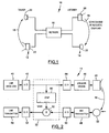
- a communication channel established between a pair of telephone devices 12 and 14 over a network 16 is shown and is generally identified by reference numeral 10.
- acoustic signals 18 broadcast by the handset speaker 20 of receiving telephone device 14 are acoustically coupled to the handset microphone 22 of the telephone device 14.
- the echo signals picked up by the handset microphone 22 as a result of the acoustic coupling cause echoes in the network 16, which degrade voice quality.
- the delay in the network 16 is long, such as for example 150ms, which may be caused by voice packetization and local area network (LAN) propagation delays, echoes in the network 16 as a result of the acoustic coupling become audile detracting from voice quality.
- LAN local area network
- an echo suppressor 32 in accordance with the present invention is provided in each of the telephone devices 12 and 14 respectively.
- Figure 2 better illustrates telephone device 14.
- telephone device 14 includes a line receiver 40 coupled between the network 16 and an analog to digital converter 42.
- Analog to digital converter 42 provides digital output to the echo suppressor 32 and to a digital to analog converter 44.
- the digital to analog converter 44 conveys its analog output to a speaker driver 46, which amplifies the analog signals before they are broadcast by the handset speaker 20.
- a microphone receiver 48 which provides output to an analog to digital converter 50.
- Analog to digital converter 50 provides digital output to the echo suppressor 32.
- Echo suppressor 32 in turn supplies output to a digital to analog converter 52 that is coupled to the network 16 via a line transmitter 54.
- the echo suppressor 32 couples the handset speaker 20 and the handset microphone 22 of the telephone device 14.
- the echo suppressor 32 adaptively masks echo signals picked up by the handset microphone 22 to inhibit echo in the network 16 using leaky masks to reduce switching effects in the presence of background noise.
- the echo suppressor 32 generates suppressions mask based on the power level of signals broadcast by the handset speaker 20. This is due to the fact that typically, the larger the signals broadcast by the handset speaker 20, the larger the echo signals picked up by the handset microphone 22 as a result of acoustic coupling tend to be.
- the echo suppressor 32 also generates noise leaking least significant bits based on the noise level of the received echo signals that are needed to leak background noise through the echo suppressor 32.
- the suppression masks and the noise leaking LSBs are combined to yield echo suppression adaptive masks that are used by the echo suppressor 32 to suppress the received echo signals.
- the echo suppressor 32 performs double-talk detection based on the power level of the received echo signals and the acoustic coupling loss between the handset speaker 20 and the handset microphone 22.
- double-talk is declared, the bits of the adaptive masks generated by the echo suppressor 32 are all set to one (1) allowing the received echo signals to pass through the echo suppressor 32 unchanged.
- the echo suppressor 32 is embodied in a programmable digital signal processor (DSP) 60.
- the DSP 60 executes an echo suppression algorithm, an echo signal noise level calculation algorithm and a double-talk detection algorithm to achieve the functionality described above. Further specifics concerning the echo suppression, echo signal noise level calculation and double-talk detection algorithms will now be described.
- the DSP 60 performs a power level calculation to determine the power level of the signal received by the telephone device 14 that is to be broadcast by the handset speaker 20 and uses the determined power level to generate the suppression mask.
- the DSP 60 calculates the noise level of the received echo signal using the method described in U.K. Patent Application Serial No. 0023975.6 filed on September 30, 2000, the content of which is incorporated herein by reference.
- the value of the calculated echo signal noise level is then used to determine the number of noise leaking bits required to leak effectively the background noise and avoid switching effects.
- the suppression mask and the noise leaking bits are then combined to yield the echo suppression adaptive mask.
- level(echo) envelope(transmit_signal)/acoustic_coupling_loss_value (e.g. 24dB) (1)
- the value for the mask is chosen based on the estimated echo signal level.
- the DSP 60 calculates the power level of the received echo signal and compares the calculated power level with a threshold value.
- the threshold value is a predefined factor of the expected echo signal level, based on the acoustic coupling loss value.
- double talk is declared whenever the signal received by the microphone 22 is bigger than the expected echo signal which, as discussed above, is equal to the envelope of transmitted signal divided by the acoustic coupling loss value.
- the expected echo signal level is determined from the power level of the signal broadcast by the handset speaker 20 and the value of the acoustic coupling loss between the handset speaker 20 and the handset microphone 22.
- the acoustic coupling loss is directly related to the acoustic properties of a given handset. It is basically always the same for a specific handset design and specific scenario/application, and has to be measured electrically or acoustically using lab equipment.
- a typical handset may be characterized by an acoustic coupling loss with the handset placed face-down on a hard desk, of -24dB, and if the handset is sealed to the ear, the acoustic coupling loss is -50dB.
- a value of -24dB is used, on the understanding that this value accomodates the worst-case scenario for the given handset.
- double-talk is declared. When double-talk is declared, all of the bits of the adaptive mask are set to one (1).
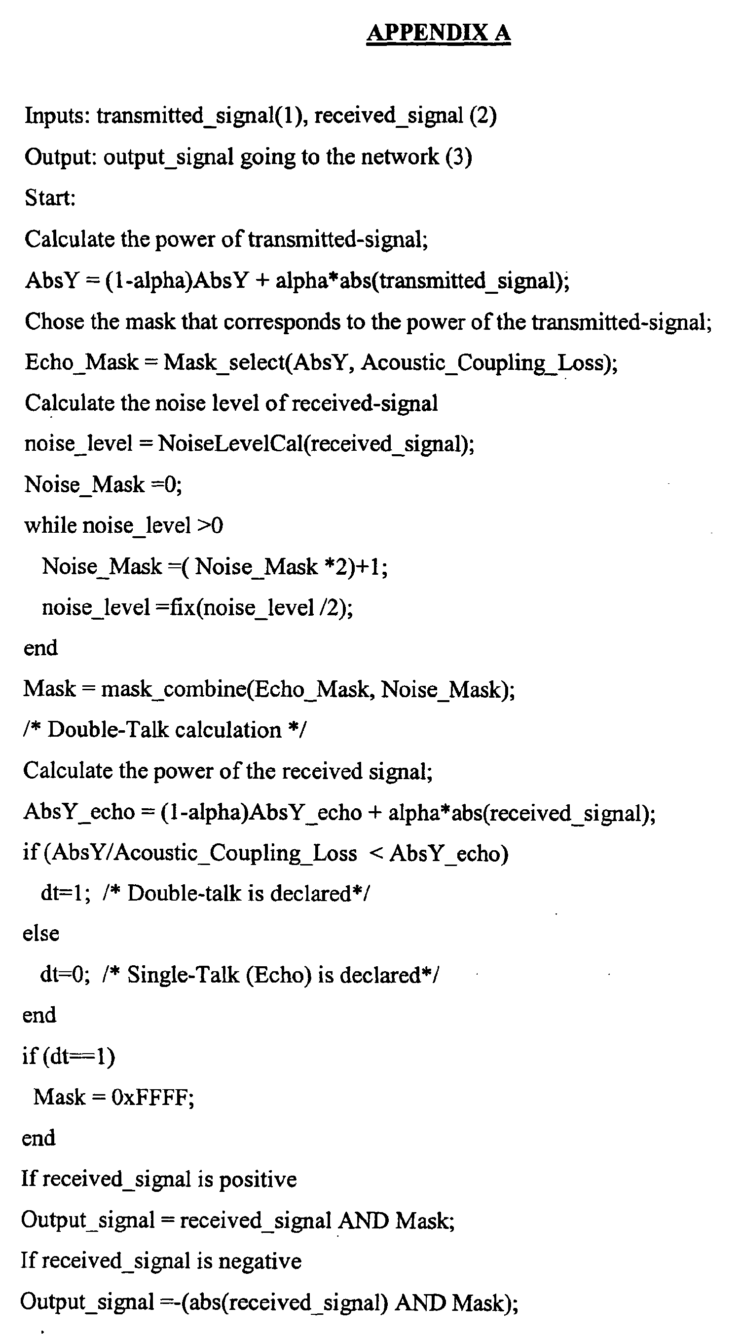
- Appendix A shows pseudo-code representing the echo suppression, echo signal noise level calculation and double-talk detection algorithms executed by the DSP 60.
- the echo suppression adaptive mask is applied to the echo signal received by the handset microphone 22 via a multiplier 62. If double-talk has been declared, the echo suppressor 32 is effectively switched off allowing the echo signal to pass through the echo suppressor 32 unchanged. If double-talk has not been declared, the echo signal is cancelled or masked with the exception of background noise that is allowed to pass through the echo suppressor 32 as a result of the noise leaking bits.
- Appendix B illustrates power level calculation and mask selection routines of the echo suppression algorithm used to calculate the power level of the signal broadcast by the handset speaker 20 and to select the appropriate suppression mask based on the calculated power level.
- an envelope following the power level of the signal broadcast by the handset speaker 20 is generated using an infinite impulse response (IIR) lowpass filter.
- the DSP 60 selects the suppression mask in accordance with the mask selection routine.
- the echo suppressor 32 by choosing these values for alpha, the echo suppressor 32 generates an envelope that reacts fast to signals broadcast by the handset speaker 20.
- the slow decay time on the other hand compensates for small signal delays and reduces the switching effect when the signals fade.
- the DSP 60 can take actual acoustic coupling between the handset speaker 20 and handset microphone 22 into account. In this case, as the envelope is generated, the DSP 60 calculates the value of the acoustic coupling loss between the handset speaker 20 and the handset microphone 22 based on the received echo signal and the measured acoustic coupling loss, as discussed above.
- level(echo) envelope(transmit_signal)/acoustic_coupling_loss_value
- a conventional echo canceller 70 is in parallel with a communication path 71 in which echo signals are generated.
- the communication path 71 may be a telephone device handset as described in the previous embodiment.
- the communication path 71 may be a hands free telephone, a network which causes network reflections, or another source of echo signals.
- the echo canceller 70 attempts to model the transfer function of the echo signal path using a least-mean-squared (LMS) algorithm and generates estimated echo signals.
- the estimated echo signals are subtracted 72 from the echo signals received by the echo canceller 70 in an attempt to cancel the received echo signals.
- the amount of cancellation is commonly referred to as ERLE.
- Differences between the estimated echo signals and the received echo signals result in residual echo signals.
- the residual echo signals are fed back to the echo canceller 70 so that the echo canceller can attempt to converge to the correct transfer function.
- the LMS algorithm only monitors linear effects in the echo path. It does not deal with non-linear effects caused for example by, clipping, telephone key rattling, and frequency shift. Therefore, the echo canceller 70 converges to a transfer function that approximates the correct transfer function resulting in non-zero residual echo signals. These non-zero residual echo signals result in echo signals in the network.
- a non-linear processor (NLP) 80 is provided and receives the estimated echo signals output by the echo canceller 70 as well as the residual echo signals output by the subtractor 72.
- the NLP 80 executes the echo suppression, echo signal noise level calculation and double-talk detection algorithms described previously.
- the leaky masks generated by the NLP 80 are combined with the residual echo signals to suppress the residual echos with the exception of background noise which is allowed to pass through the NLP 80 as a result of the noise leaking bits.
- the NLP 80 needs to be active only during the echo periods, and should be switched off during double-silence and double-talk periods. Since it is not a straightforward matter to correctly determine exactly when the NLP should be switched on, it is important to reduce the speech degradation in cases when the NLP 80 has been incorrectly switched on during periods of double-talk.
- Some NLP designs totally cut-off the signal when echo is present and replace the signal with regenerated noise or even silence. Obviously, if such an NLP is active when near end speech signal is present, instead of echo, the speech will be cut-off and distorted. According to the present invention, the large mask introduces more distortion to the speech than a smaller mask, because it clears more bits of information.
- the preferred embodiment of the echo suppressor 32 is described with reference to a programmable DSP, those of skill in the art will appreciate that alternative implementations can be used.
- the algorithms may be run on a hardware ASIC (i.e. a non-programmable digital processing device) or other comparable hardware device.
Landscapes
- Engineering & Computer Science (AREA)
- Signal Processing (AREA)
- Computer Networks & Wireless Communication (AREA)
- Cable Transmission Systems, Equalization Of Radio And Reduction Of Echo (AREA)
- Telephone Function (AREA)
- Interconnected Communication Systems, Intercoms, And Interphones (AREA)
Abstract
Description
- The present invention relates generally to telecommunications and in particular to echo cancellation/suppression and double-talk detection in communication paths.
- Acoustic coupling in telephone device handsets is common and occurs when signals broadcast by the speaker of a telephone device are coupled to the microphone of the same telephone device. This acoustic coupling causes echo signals in the network over which the communication channel is established. The acoustic suppression of signals broadcast by the handset speaker before they are picked up by the handset microphone is variable and depends on a number of factors, such as for example, the pressure exerted on the user's ear by the handset speaker and how well the handset speaker seals the user's ear. The loss in power of these signals as a result of acoustic suppression can vary from about -50db to as low as -24db when the telephone device handset is placed on a hard surface. If delays in the network are short (i.e. 30ms), the normal acoustic suppression of signals broadcast by the handset speaker is generally sufficient to inhibit voice quality from being noticeably degraded by echo signals picked up by the handset microphone. However, if the delays in the network are significant, echo signals in the network due to acoustic coupling will noticeably degrade voice quality over the communication channel. As such, suppressing echo signals resulting from acoustic coupling in telephone devices is important.
- Echo cancellers in telephone devices have been considered. A typical echo canceller attempts to model the transfer function of the echo signal path using a linear algorithm such as a Least-Mean-Squared (LMS) algorithm. The estimated echo signals generated by the echo canceller are subtracted from the echo signals picked up by the handset microphone. Differences between the estimated echo signals and the actual echo signals result in error signals, which are fed back to the echo canceller. Unfortunately, since the algorithm executed by the echo canceller is linear, the echo canceller cannot deal with non-linear effects and can only converge to a transfer function that approximates the echo signals. As a result, residual echo signals propagate through the echo canceller to the network.
- To deal with the deficiencies noted above, an echo suppressor has been considered and is described in U.K. Patent Application Serial No. 9907102.9 filed on March 26, 1999. This echo suppressor includes a power level calculator that determines the power level of signals broadcast by the handset speaker. A mask generator is responsive to the power level calculator and generates masks that are a function of the determined power levels to suppress echo signals received by the handset microphone. To avoid noticeable switching effects in the presence of background noise, the echo suppressor can be conditioned to generate leaky masks. This is achieved by setting one or a few of the least significant bits (LSBs) in the masks to one (1) so that the lower bits of the received echo signals are leaked through the echo suppressor.
- Although this echo suppressor works well to suppress echo, since the number of least significant bits in the masks that are set to one to leak echo signals is static, switching effects that degrade voice quality still result. Also, since the echo suppressor is active all the time with the number of zeros in the masks changing depending on the power level of the signals broadcast by the handset speaker, the echo suppressor degrades speech quality during double-talk situations. As will be appreciated, improvements in echo cancellation/suppression are desired.
- It is therefore an object of the present invention to provide a novel echo suppressor and method for suppressing echoes in a communication path.
- According to one aspect of the present invention there is provided a method of suppressing an echo signal in a communication path comprising the steps of:
- monitoring a transmitted signal supplied to said communication path to determine an attribute thereof;
- generating a leaky mask based on said determined attribute and an attribute of a received echo signal; and
- partially cancelling said received echo signal using said leaky mask
-
- Preferably, the attribute of the transmitted signal is the power level thereof and the attribute of the received echo signal is the noise level thereof. In the preferred embodiment, the generating includes the steps of generating a suppression mask based on the power level of the transmitted signal; generating noise leaking bits based on the noise level of the received echo signal; and combining the suppression mask and the noise leaking bits to yield the leaky mask.
- It is also preferred that the partially cancelling of step is inhibited in the presence of double-talk. Double-talk is declared when the power level of the received echo signal exceeds a threshold value.
- In another embodiment, it is preferred that during the generating, an estimated echo signal is also generated based on the power level of the transmitted signal and that the partially cancelling step is performed after the estimated echo signal is subtracted from the received echo signal.
- According to another aspect of the present invention there is provided an echo suppressor to suppress an echo signal in a communication path comprising:
- a digital signal processor for determining the power level of a transmitted signal supplied to said communication path and for determining the noise level of a received echo signal, said digital signal processor generating a leaky mask based on the determined power level and the determined noise level; and
- a multiplier for combining said leaky mask and said received echo signal thereby to suppress partially said received echo signal.
-
- The present invention provides advantages in that since the echo suppressor generates adaptive leaky masks, echo suppression is achieved while maintaining voice quality and avoiding switching effects in the presence of background noise. Also, since echo suppression is switched off in the presence of double-talk, voice quality is maintained in double-talk situations.
- Embodiments of the present invention will now be described more fully with reference to the accompanying drawings in which:
- Figure 1 is a schematic diagram of a communication channel established between a pair of telephone devices over a network showing acoustic coupling in one of the telephone devices;
- Figure 2 is a schematic diagram of a telephone device including an echo suppressor in accordance with the present invention;
- Figure 3 is a graph showing an envelope calculated by the echo suppressor of Figure 2 following the power level of a signal broadcast by a telephone device handset speaker; and
- Figure 4 is a schematic diagram of a conventional echo canceller and a non-linear processor to suppress residual echo signals in accordance with the present invention.
-
- Turning now to Figure 1, a communication channel established between a pair of
telephone devices network 16 is shown and is generally identified byreference numeral 10. As can be seen, when a communication channel is established between thetelephone devices acoustic signals 18 broadcast by thehandset speaker 20 of receivingtelephone device 14 are acoustically coupled to thehandset microphone 22 of thetelephone device 14. The echo signals picked up by thehandset microphone 22 as a result of the acoustic coupling cause echoes in thenetwork 16, which degrade voice quality. If the delay in thenetwork 16 is long, such as for example 150ms, which may be caused by voice packetization and local area network (LAN) propagation delays, echoes in thenetwork 16 as a result of the acoustic coupling become audile detracting from voice quality. - To suppress adaptively echo signals picked up by the
handset microphone 22 as a result of acoustic coupling, anecho suppressor 32 in accordance with the present invention is provided in each of thetelephone devices telephone device 14. As can be seen,telephone device 14 includes aline receiver 40 coupled between thenetwork 16 and an analog todigital converter 42. Analog todigital converter 42 provides digital output to theecho suppressor 32 and to a digital toanalog converter 44. The digital toanalog converter 44 conveys its analog output to aspeaker driver 46, which amplifies the analog signals before they are broadcast by thehandset speaker 20. - Coupled to the
handset microphone 22 is amicrophone receiver 48, which provides output to an analog todigital converter 50. Analog todigital converter 50 provides digital output to theecho suppressor 32. Echosuppressor 32 in turn supplies output to a digital toanalog converter 52 that is coupled to thenetwork 16 via aline transmitter 54. - The
echo suppressor 32 couples thehandset speaker 20 and thehandset microphone 22 of thetelephone device 14. Theecho suppressor 32 adaptively masks echo signals picked up by thehandset microphone 22 to inhibit echo in thenetwork 16 using leaky masks to reduce switching effects in the presence of background noise. Specifically, theecho suppressor 32 generates suppressions mask based on the power level of signals broadcast by thehandset speaker 20. This is due to the fact that typically, the larger the signals broadcast by thehandset speaker 20, the larger the echo signals picked up by thehandset microphone 22 as a result of acoustic coupling tend to be. Theecho suppressor 32 also generates noise leaking least significant bits based on the noise level of the received echo signals that are needed to leak background noise through theecho suppressor 32. The suppression masks and the noise leaking LSBs are combined to yield echo suppression adaptive masks that are used by theecho suppressor 32 to suppress the received echo signals. - In addition, the
echo suppressor 32 performs double-talk detection based on the power level of the received echo signals and the acoustic coupling loss between thehandset speaker 20 and thehandset microphone 22. When double-talk is declared, the bits of the adaptive masks generated by theecho suppressor 32 are all set to one (1) allowing the received echo signals to pass through theecho suppressor 32 unchanged. - In the present embodiment, the
echo suppressor 32 is embodied in a programmable digital signal processor (DSP) 60. TheDSP 60 executes an echo suppression algorithm, an echo signal noise level calculation algorithm and a double-talk detection algorithm to achieve the functionality described above. Further specifics concerning the echo suppression, echo signal noise level calculation and double-talk detection algorithms will now be described. During execution of the echo suppression algorithm, theDSP 60 performs a power level calculation to determine the power level of the signal received by thetelephone device 14 that is to be broadcast by thehandset speaker 20 and uses the determined power level to generate the suppression mask. - During execution of the echo signal noise level calculation routine, the
DSP 60 calculates the noise level of the received echo signal using the method described in U.K. Patent Application Serial No. 0023975.6 filed on September 30, 2000, the content of which is incorporated herein by reference. The value of the calculated echo signal noise level is then used to determine the number of noise leaking bits required to leak effectively the background noise and avoid switching effects. The suppression mask and the noise leaking bits are then combined to yield the echo suppression adaptive mask. - More particularly, the level of echo signal is calculated based on the envelope of transmitted signal and echo suppression value using the formula: level(echo) = envelope(transmit_signal)/acoustic_coupling_loss_value (e.g. 24dB) (1) The value for the mask is chosen based on the estimated echo signal level. The number of noise leaking bits is chosen based on the calculated level of background noise picked up by the
microphone 22. For example, if the estimated echo signal level is equal to 256 (2^8), then the mask needed to completely suppress the echo will have 8 LSBs equal to zero (i.e. ECHO_MASK=0xFF00). If the value for the estimated noise is equal to 7, the number of bits needed to leak the noise through is 3, (i.e. NOISE_MASK = 0x0007). The echo suppression adaptive mask is then calculated using the formula: - During execution of the double-talk detection algorithm, the
DSP 60 calculates the power level of the received echo signal and compares the calculated power level with a threshold value. The threshold value is a predefined factor of the expected echo signal level, based on the acoustic coupling loss value. In simple terms, double talk is declared whenever the signal received by themicrophone 22 is bigger than the expected echo signal which, as discussed above, is equal to the envelope of transmitted signal divided by the acoustic coupling loss value. The expected echo signal level is determined from the power level of the signal broadcast by thehandset speaker 20 and the value of the acoustic coupling loss between thehandset speaker 20 and thehandset microphone 22. The acoustic coupling loss is directly related to the acoustic properties of a given handset. It is basically always the same for a specific handset design and specific scenario/application, and has to be measured electrically or acoustically using lab equipment. - For example, a typical handset may be characterized by an acoustic coupling loss with the handset placed face-down on a hard desk, of -24dB, and if the handset is sealed to the ear, the acoustic coupling loss is -50dB. In the algorithm for implementing the preferred embodiment of the invention, a value of -24dB is used, on the understanding that this value accomodates the worst-case scenario for the given handset. If the calculated echo signal power level is greater than the threshold value, double-talk is declared. When double-talk is declared, all of the bits of the adaptive mask are set to one (1). Appendix A shows pseudo-code representing the echo suppression, echo signal noise level calculation and double-talk detection algorithms executed by the
DSP 60. - Once the echo suppression adaptive mask is established, the echo suppression adaptive mask is applied to the echo signal received by the
handset microphone 22 via amultiplier 62. If double-talk has been declared, theecho suppressor 32 is effectively switched off allowing the echo signal to pass through theecho suppressor 32 unchanged. If double-talk has not been declared, the echo signal is cancelled or masked with the exception of background noise that is allowed to pass through theecho suppressor 32 as a result of the noise leaking bits. - Appendix B illustrates power level calculation and mask selection routines of the echo suppression algorithm used to calculate the power level of the signal broadcast by the
handset speaker 20 and to select the appropriate suppression mask based on the calculated power level. During execution of the power level calculation routine, an envelope following the power level of the signal broadcast by thehandset speaker 20 is generated using an infinite impulse response (IIR) lowpass filter. The IIR filter generates the envelope by estimating the long-range average of the absolute value of the signal broadcast by thehandset speaker 20 and is of the form:handset speaker 20. Once the envelope has been generated, theDSP 60 selects the suppression mask in accordance with the mask selection routine. - Figure 3 shows an example of an
envelope 64 generated by theecho suppressor 32 in response to a signal broadcast by thehandset speaker 20 where alpha_fast = 1 and alpha_slow = 2-12. As will be appreciated, by choosing these values for alpha, theecho suppressor 32 generates an envelope that reacts fast to signals broadcast by thehandset speaker 20. The slow decay time on the other hand compensates for small signal delays and reduces the switching effect when the signals fade. - If desired, the
DSP 60 can take actual acoustic coupling between thehandset speaker 20 andhandset microphone 22 into account. In this case, as the envelope is generated, theDSP 60 calculates the value of the acoustic coupling loss between thehandset speaker 20 and thehandset microphone 22 based on the received echo signal and the measured acoustic coupling loss, as discussed above. After the value of the acoustic coupling loss has been calculated, the mask selection routine selects the suppression mask in accordance with the routine illustrated in Appendix B, from which it will be noted that suppression mask is calculated based on the level of expected echo, which is: - Turning now to Figure 4, an alternative embodiment of the present invention is shown. In this embodiment, a
conventional echo canceller 70 is in parallel with acommunication path 71 in which echo signals are generated. Thecommunication path 71 may be a telephone device handset as described in the previous embodiment. Alternatively, thecommunication path 71 may be a hands free telephone, a network which causes network reflections, or another source of echo signals. The echo canceller 70 attempts to model the transfer function of the echo signal path using a least-mean-squared (LMS) algorithm and generates estimated echo signals. The estimated echo signals are subtracted 72 from the echo signals received by theecho canceller 70 in an attempt to cancel the received echo signals. The amount of cancellation is commonly referred to as ERLE. Differences between the estimated echo signals and the received echo signals result in residual echo signals. The residual echo signals are fed back to theecho canceller 70 so that the echo canceller can attempt to converge to the correct transfer function. - Unfortunately, the LMS algorithm only monitors linear effects in the echo path. It does not deal with non-linear effects caused for example by, clipping, telephone key rattling, and frequency shift. Therefore, the
echo canceller 70 converges to a transfer function that approximates the correct transfer function resulting in non-zero residual echo signals. These non-zero residual echo signals result in echo signals in the network. - To suppress the residual echo signals, a non-linear processor (NLP) 80 is provided and receives the estimated echo signals output by the
echo canceller 70 as well as the residual echo signals output by thesubtractor 72. TheNLP 80 executes the echo suppression, echo signal noise level calculation and double-talk detection algorithms described previously. The leaky masks generated by theNLP 80 are combined with the residual echo signals to suppress the residual echos with the exception of background noise which is allowed to pass through theNLP 80 as a result of the noise leaking bits. - Taking actual acoustic coupling into account is particularly of interest in this environment especially in situations where the existence of double-talk is indeterminate. The
NLP 80 needs to be active only during the echo periods, and should be switched off during double-silence and double-talk periods. Since it is not a straightforward matter to correctly determine exactly when the NLP should be switched on, it is important to reduce the speech degradation in cases when theNLP 80 has been incorrectly switched on during periods of double-talk. Some NLP designs totally cut-off the signal when echo is present and replace the signal with regenerated noise or even silence. Obviously, if such an NLP is active when near end speech signal is present, instead of echo, the speech will be cut-off and distorted. According to the present invention, the large mask introduces more distortion to the speech than a smaller mask, because it clears more bits of information. - Although the preferred embodiment of the
echo suppressor 32 is described with reference to a programmable DSP, those of skill in the art will appreciate that alternative implementations can be used. For example, the algorithms may be run on a hardware ASIC (i.e. a non-programmable digital processing device) or other comparable hardware device. - Although preferred embodiments of the present invention have been described, those of skill in the art will appreciate that variations and modifications may be made without departing from the spirit and scope thereof as defined by the appended claims.


Claims (12)
- A method of suppressing an echo signal in a communication path comprising the steps of:monitoring a transmitted signal supplied to said communication path to determine an attribute thereof;generating a leaky mask based on said determined attribute and an attribute of a received echo signal; andpartially cancelling said received echo signal using said leaky mask.
- The method of claim 1 wherein the attribute of said transmitted signal is the power level thereof.
- The method of claim 1 or 2 wherein the attribute of the received echo signal is the noise level thereof.
- The method of claim 3 wherein said generating includes the steps of:generating a suppression mask based on the power level of said transmitted signal;generating noise leaking bits based on the noise level of said received echo signal; andcombining said suppression mask and noise leaking bits to yield said leaky mask.
- The method of any one of claims 1 to 4 further comprising the step of inhibiting said partial cancelling in the presence of double-talk.
- The method of claim 5 wherein double-talk is declared when the power level of said received echo signal exceeds a threshold value.
- The method of claim 2 wherein during said generating, an estimated echo signal is also generated based on the power level of said transmitted signal and wherein the partially cancelling step is performed after the estimated echo signal is subtracted from the received echo signal.
- The method of claim 7 further comprising the step of inhibiting said partial cancelling in the presence of double-talk.
- The method of claim 8 wherein double-talk is declared when the power level of said received echo signal exceeds a threshold value.
- An echo suppressor to suppress an echo signal in a communication path comprising:a digital signal processor for determining the power level of a transmitted signal supplied to said communication path and for determining the noise level of a received echo signal, said digital signal processor generating a leaky mask based on the determined power level and the determined noise level; anda multiplier for combining said leaky mask and said received echo signal thereby to suppress partially said received echo signal.
- An echo suppressor according to claim 10 wherein said digital signal processor conditions said leaky mask to a full pass state in the presence of double-talk on said communication path.
- An echo suppressor according to claim 11 wherein said digital signal processor conditions said leaky mask to said full pass state when the power level of the received echo signal exceeds a threshold value.
Applications Claiming Priority (2)
| Application Number | Priority Date | Filing Date | Title |
|---|---|---|---|
| GB0302219A GB2397990A (en) | 2003-01-31 | 2003-01-31 | Echo cancellation/suppression and double-talk detection in communication paths |
| GB0302219 | 2003-01-31 |
Publications (2)
| Publication Number | Publication Date |
|---|---|
| EP1443674A1 true EP1443674A1 (en) | 2004-08-04 |
| EP1443674B1 EP1443674B1 (en) | 2011-07-20 |
Family
ID=9952173
Family Applications (1)
| Application Number | Title | Priority Date | Filing Date |
|---|---|---|---|
| EP04250395A Expired - Lifetime EP1443674B1 (en) | 2003-01-31 | 2004-01-24 | Echo cancellation with double-talk detection |
Country Status (5)
| Country | Link |
|---|---|
| US (1) | US7212628B2 (en) |
| EP (1) | EP1443674B1 (en) |
| AT (1) | ATE517473T1 (en) |
| CA (1) | CA2453867C (en) |
| GB (1) | GB2397990A (en) |
Families Citing this family (40)
| Publication number | Priority date | Publication date | Assignee | Title |
|---|---|---|---|---|
| US8457614B2 (en) | 2005-04-07 | 2013-06-04 | Clearone Communications, Inc. | Wireless multi-unit conference phone |
| JP2007235502A (en) * | 2006-03-01 | 2007-09-13 | Sony Corp | Audio communication system |
| US8949120B1 (en) | 2006-05-25 | 2015-02-03 | Audience, Inc. | Adaptive noise cancelation |
| US8199927B1 (en) | 2007-10-31 | 2012-06-12 | ClearOnce Communications, Inc. | Conferencing system implementing echo cancellation and push-to-talk microphone detection using two-stage frequency filter |
| US8050398B1 (en) | 2007-10-31 | 2011-11-01 | Clearone Communications, Inc. | Adaptive conferencing pod sidetone compensator connecting to a telephonic device having intermittent sidetone |
| TR201815047T4 (en) | 2008-12-22 | 2018-11-21 | Anheuser Busch Inbev Sa | Determining an acoustic coupling between a remote end signal and a composite signal. |
| CN101719969B (en) * | 2009-11-26 | 2013-10-02 | 美商威睿电通公司 | Method and system for judging double-end conversation and method and system for eliminating echo |
| US8718290B2 (en) | 2010-01-26 | 2014-05-06 | Audience, Inc. | Adaptive noise reduction using level cues |
| US8473287B2 (en) | 2010-04-19 | 2013-06-25 | Audience, Inc. | Method for jointly optimizing noise reduction and voice quality in a mono or multi-microphone system |
| US9343073B1 (en) * | 2010-04-20 | 2016-05-17 | Knowles Electronics, Llc | Robust noise suppression system in adverse echo conditions |
| US20120195438A1 (en) | 2011-01-28 | 2012-08-02 | Mitel Networks Corporation | Echo suppression for wireless handsets and headsets |
| US9307321B1 (en) | 2011-06-09 | 2016-04-05 | Audience, Inc. | Speaker distortion reduction |
| CN103516921A (en) | 2012-06-28 | 2014-01-15 | 杜比实验室特许公司 | Method for controlling echo through hiding audio signals |
| GB201309779D0 (en) * | 2013-05-31 | 2013-07-17 | Microsoft Corp | Echo removal |
| GB201309773D0 (en) | 2013-05-31 | 2013-07-17 | Microsoft Corp | Echo removal |
| US9554207B2 (en) | 2015-04-30 | 2017-01-24 | Shure Acquisition Holdings, Inc. | Offset cartridge microphones |
| US9565493B2 (en) | 2015-04-30 | 2017-02-07 | Shure Acquisition Holdings, Inc. | Array microphone system and method of assembling the same |
| US20170338804A1 (en) * | 2016-05-14 | 2017-11-23 | Vssl Llc | Apparatus, System, and Method for an Acoustic Response Monitor |
| US10367948B2 (en) | 2017-01-13 | 2019-07-30 | Shure Acquisition Holdings, Inc. | Post-mixing acoustic echo cancellation systems and methods |
| EP3804356A1 (en) | 2018-06-01 | 2021-04-14 | Shure Acquisition Holdings, Inc. | Pattern-forming microphone array |
| US11297423B2 (en) | 2018-06-15 | 2022-04-05 | Shure Acquisition Holdings, Inc. | Endfire linear array microphone |
| US11310596B2 (en) | 2018-09-20 | 2022-04-19 | Shure Acquisition Holdings, Inc. | Adjustable lobe shape for array microphones |
| US11363147B2 (en) | 2018-09-25 | 2022-06-14 | Sorenson Ip Holdings, Llc | Receive-path signal gain operations |
| TWI865506B (en) | 2019-03-21 | 2024-12-11 | 美商舒爾獲得控股公司 | Auto focus, auto focus within regions, and auto placement of beamformed microphone lobes with inhibition functionality |
| EP3942842B1 (en) | 2019-03-21 | 2026-03-11 | Shure Acquisition Holdings, Inc. | Housings and associated design features for ceiling array microphones |
| US11558693B2 (en) | 2019-03-21 | 2023-01-17 | Shure Acquisition Holdings, Inc. | Auto focus, auto focus within regions, and auto placement of beamformed microphone lobes with inhibition and voice activity detection functionality |
| CN114051738B (en) | 2019-05-23 | 2024-10-01 | 舒尔获得控股公司 | Steerable speaker array, system and method thereof |
| CN114051637B (en) | 2019-05-31 | 2025-10-28 | 舒尔获得控股公司 | Low-latency automatic mixer with integrated voice and noise activity detection |
| WO2021041275A1 (en) | 2019-08-23 | 2021-03-04 | Shore Acquisition Holdings, Inc. | Two-dimensional microphone array with improved directivity |
| WO2021087377A1 (en) | 2019-11-01 | 2021-05-06 | Shure Acquisition Holdings, Inc. | Proximity microphone |
| US11552611B2 (en) | 2020-02-07 | 2023-01-10 | Shure Acquisition Holdings, Inc. | System and method for automatic adjustment of reference gain |
| JP7382273B2 (en) * | 2020-04-13 | 2023-11-16 | 株式会社トランストロン | Echo suppression device, echo suppression method and echo suppression program |
| WO2021243368A2 (en) | 2020-05-29 | 2021-12-02 | Shure Acquisition Holdings, Inc. | Transducer steering and configuration systems and methods using a local positioning system |
| JP7814400B2 (en) | 2021-01-28 | 2026-02-16 | シュアー アクイジッション ホールディングス インコーポレイテッド | Hybrid Audio Beamforming System |
| US12452584B2 (en) | 2021-01-29 | 2025-10-21 | Shure Acquisition Holdings, Inc. | Scalable conferencing systems and methods |
| US12542123B2 (en) | 2021-08-31 | 2026-02-03 | Shure Acquisition Holdings, Inc. | Mask non-linear processor for acoustic echo cancellation |
| US12289584B2 (en) | 2021-10-04 | 2025-04-29 | Shure Acquisition Holdings, Inc. | Networked automixer systems and methods |
| US12525083B2 (en) | 2021-11-05 | 2026-01-13 | Shure Acquisition Holdings, Inc. | Distributed algorithm for automixing speech over wireless networks |
| US12250526B2 (en) | 2022-01-07 | 2025-03-11 | Shure Acquisition Holdings, Inc. | Audio beamforming with nulling control system and methods |
| US12598261B2 (en) | 2022-09-28 | 2026-04-07 | Shure Acquisition Holdings, Inc. | Wideband doubletalk detection for optimization of acoustic echo cancellation |
Citations (3)
| Publication number | Priority date | Publication date | Assignee | Title |
|---|---|---|---|---|
| GB2348350A (en) * | 1999-03-26 | 2000-09-27 | Mitel Corp | Echo cancelling/suppression for handsets |
| US6282286B1 (en) * | 1997-10-24 | 2001-08-28 | Mitel Corporation | Nonlinear processor for acoustic echo canceller with background noise preservation and long echo tail suppression |
| US20020184013A1 (en) * | 2001-04-20 | 2002-12-05 | Alcatel | Method of masking noise modulation and disturbing noise in voice communication |
Family Cites Families (7)
| Publication number | Priority date | Publication date | Assignee | Title |
|---|---|---|---|---|
| US3991287A (en) * | 1975-04-24 | 1976-11-09 | Bell Telephone Laboratories, Incorporated | Digital echo suppressor noise insertion |
| US4243959A (en) * | 1979-06-21 | 1981-01-06 | Bell Telephone Laboratories, Incorporated | Adaptive filter with tap coefficient leakage |
| US5295136A (en) * | 1992-04-13 | 1994-03-15 | Motorola, Inc. | Method of performing convergence in a, least mean square, adaptive filter, echo canceller |
| US5535194A (en) * | 1994-07-14 | 1996-07-09 | Motorola, Inc. | Method and apparatus for echo canceling with double-talk immunity |
| US6282176B1 (en) * | 1998-03-20 | 2001-08-28 | Cirrus Logic, Inc. | Full-duplex speakerphone circuit including a supplementary echo suppressor |
| US6347140B1 (en) * | 1999-08-12 | 2002-02-12 | Motorola, Inc. | Echo canceling method and apparatus |
| GB2367467B (en) * | 2000-09-30 | 2004-12-15 | Mitel Corp | Noise level calculator for echo canceller |
-
2003
- 2003-01-31 GB GB0302219A patent/GB2397990A/en not_active Withdrawn
- 2003-12-18 CA CA002453867A patent/CA2453867C/en not_active Expired - Lifetime
-
2004
- 2004-01-24 EP EP04250395A patent/EP1443674B1/en not_active Expired - Lifetime
- 2004-01-24 AT AT04250395T patent/ATE517473T1/en not_active IP Right Cessation
- 2004-01-26 US US10/765,465 patent/US7212628B2/en not_active Expired - Lifetime
Patent Citations (3)
| Publication number | Priority date | Publication date | Assignee | Title |
|---|---|---|---|---|
| US6282286B1 (en) * | 1997-10-24 | 2001-08-28 | Mitel Corporation | Nonlinear processor for acoustic echo canceller with background noise preservation and long echo tail suppression |
| GB2348350A (en) * | 1999-03-26 | 2000-09-27 | Mitel Corp | Echo cancelling/suppression for handsets |
| US20020184013A1 (en) * | 2001-04-20 | 2002-12-05 | Alcatel | Method of masking noise modulation and disturbing noise in voice communication |
Also Published As
| Publication number | Publication date |
|---|---|
| US7212628B2 (en) | 2007-05-01 |
| CA2453867C (en) | 2008-05-13 |
| US20040247111A1 (en) | 2004-12-09 |
| CA2453867A1 (en) | 2004-07-31 |
| ATE517473T1 (en) | 2011-08-15 |
| EP1443674B1 (en) | 2011-07-20 |
| GB2397990A (en) | 2004-08-04 |
| GB0302219D0 (en) | 2003-03-05 |
Similar Documents
| Publication | Publication Date | Title |
|---|---|---|
| EP1443674B1 (en) | Echo cancellation with double-talk detection | |
| US5668794A (en) | Variable gain echo suppressor | |
| US6999582B1 (en) | Echo cancelling/suppression for handsets | |
| US7856097B2 (en) | Echo canceling apparatus, telephone set using the same, and echo canceling method | |
| CN101262530B (en) | A device for eliminating echo of mobile terminal | |
| US5631900A (en) | Double-Talk detector for echo canceller | |
| US7203308B2 (en) | Echo canceller ensuring further reduction in residual echo | |
| US6434110B1 (en) | Full-duplex speakerphone circuit including a double-talk detector | |
| US8634569B2 (en) | Systems and methods for echo cancellation and echo suppression | |
| US5764753A (en) | Half-duplex controller | |
| JP4457639B2 (en) | Echo canceller | |
| JP5086769B2 (en) | Loudspeaker | |
| EP0914721A2 (en) | Echo canceler for non-linear circuits | |
| US20020181698A1 (en) | Sound communication device and echo processor | |
| US6178162B1 (en) | Method and apparatus for inhibiting echo in a channel of a communication system | |
| CN102405634B (en) | Speakerphone apparatus | |
| JP5712350B2 (en) | Loudspeaker | |
| GB2330746A (en) | Echo canceller with double talk | |
| JP3220979B2 (en) | Voice switch | |
| JP4900185B2 (en) | Loudspeaker | |
| JPH0459812B2 (en) | ||
| JP3082899B2 (en) | Echo canceller | |
| JP5297396B2 (en) | Loudspeaker | |
| JPS6129178B2 (en) | ||
| JP3248550B2 (en) | Echo canceler |
Legal Events
| Date | Code | Title | Description |
|---|---|---|---|
| PUAI | Public reference made under article 153(3) epc to a published international application that has entered the european phase |
Free format text: ORIGINAL CODE: 0009012 |
|
| 17P | Request for examination filed |
Effective date: 20040211 |
|
| AK | Designated contracting states |
Kind code of ref document: A1 Designated state(s): AT BE BG CH CY CZ DE DK EE ES FI FR GB GR HU IE IT LI LU MC NL PT RO SE SI SK TR |
|
| AX | Request for extension of the european patent |
Extension state: AL LT LV MK |
|
| AKX | Designation fees paid |
Designated state(s): AT BE BG CH CY CZ DE DK EE ES FI FR GB GR HU IE IT LI LU MC NL PT RO SE SI SK TR |
|
| RAP1 | Party data changed (applicant data changed or rights of an application transferred) |
Owner name: CELTIC TECH JET LIMITED |
|
| RAP1 | Party data changed (applicant data changed or rights of an application transferred) |
Owner name: MITEL NETWORKS CORPORATION |
|
| 17Q | First examination report despatched |
Effective date: 20090910 |
|
| GRAP | Despatch of communication of intention to grant a patent |
Free format text: ORIGINAL CODE: EPIDOSNIGR1 |
|
| GRAS | Grant fee paid |
Free format text: ORIGINAL CODE: EPIDOSNIGR3 |
|
| GRAA | (expected) grant |
Free format text: ORIGINAL CODE: 0009210 |
|
| AK | Designated contracting states |
Kind code of ref document: B1 Designated state(s): AT BE BG CH CY CZ DE DK EE ES FI FR GB GR HU IE IT LI LU MC NL PT RO SE SI SK TR |
|
| REG | Reference to a national code |
Ref country code: GB Ref legal event code: FG4D |
|
| REG | Reference to a national code |
Ref country code: CH Ref legal event code: EP |
|
| REG | Reference to a national code |
Ref country code: DE Ref legal event code: R096 Ref document number: 602004033521 Country of ref document: DE Effective date: 20110908 |
|
| REG | Reference to a national code |
Ref country code: NL Ref legal event code: VDEP Effective date: 20110720 |
|
| REG | Reference to a national code |
Ref country code: AT Ref legal event code: MK05 Ref document number: 517473 Country of ref document: AT Kind code of ref document: T Effective date: 20110720 |
|
| PG25 | Lapsed in a contracting state [announced via postgrant information from national office to epo] |
Ref country code: FI Free format text: LAPSE BECAUSE OF FAILURE TO SUBMIT A TRANSLATION OF THE DESCRIPTION OR TO PAY THE FEE WITHIN THE PRESCRIBED TIME-LIMIT Effective date: 20110720 Ref country code: NL Free format text: LAPSE BECAUSE OF FAILURE TO SUBMIT A TRANSLATION OF THE DESCRIPTION OR TO PAY THE FEE WITHIN THE PRESCRIBED TIME-LIMIT Effective date: 20110720 Ref country code: PT Free format text: LAPSE BECAUSE OF FAILURE TO SUBMIT A TRANSLATION OF THE DESCRIPTION OR TO PAY THE FEE WITHIN THE PRESCRIBED TIME-LIMIT Effective date: 20111121 Ref country code: SE Free format text: LAPSE BECAUSE OF FAILURE TO SUBMIT A TRANSLATION OF THE DESCRIPTION OR TO PAY THE FEE WITHIN THE PRESCRIBED TIME-LIMIT Effective date: 20110720 Ref country code: BE Free format text: LAPSE BECAUSE OF FAILURE TO SUBMIT A TRANSLATION OF THE DESCRIPTION OR TO PAY THE FEE WITHIN THE PRESCRIBED TIME-LIMIT Effective date: 20110720 |
|
| PG25 | Lapsed in a contracting state [announced via postgrant information from national office to epo] |
Ref country code: CY Free format text: LAPSE BECAUSE OF FAILURE TO SUBMIT A TRANSLATION OF THE DESCRIPTION OR TO PAY THE FEE WITHIN THE PRESCRIBED TIME-LIMIT Effective date: 20110720 Ref country code: AT Free format text: LAPSE BECAUSE OF FAILURE TO SUBMIT A TRANSLATION OF THE DESCRIPTION OR TO PAY THE FEE WITHIN THE PRESCRIBED TIME-LIMIT Effective date: 20110720 Ref country code: GR Free format text: LAPSE BECAUSE OF FAILURE TO SUBMIT A TRANSLATION OF THE DESCRIPTION OR TO PAY THE FEE WITHIN THE PRESCRIBED TIME-LIMIT Effective date: 20111021 Ref country code: SI Free format text: LAPSE BECAUSE OF FAILURE TO SUBMIT A TRANSLATION OF THE DESCRIPTION OR TO PAY THE FEE WITHIN THE PRESCRIBED TIME-LIMIT Effective date: 20110720 |
|
| PG25 | Lapsed in a contracting state [announced via postgrant information from national office to epo] |
Ref country code: CZ Free format text: LAPSE BECAUSE OF FAILURE TO SUBMIT A TRANSLATION OF THE DESCRIPTION OR TO PAY THE FEE WITHIN THE PRESCRIBED TIME-LIMIT Effective date: 20110720 Ref country code: SK Free format text: LAPSE BECAUSE OF FAILURE TO SUBMIT A TRANSLATION OF THE DESCRIPTION OR TO PAY THE FEE WITHIN THE PRESCRIBED TIME-LIMIT Effective date: 20110720 |
|
| PLBE | No opposition filed within time limit |
Free format text: ORIGINAL CODE: 0009261 |
|
| STAA | Information on the status of an ep patent application or granted ep patent |
Free format text: STATUS: NO OPPOSITION FILED WITHIN TIME LIMIT |
|
| PG25 | Lapsed in a contracting state [announced via postgrant information from national office to epo] |
Ref country code: RO Free format text: LAPSE BECAUSE OF FAILURE TO SUBMIT A TRANSLATION OF THE DESCRIPTION OR TO PAY THE FEE WITHIN THE PRESCRIBED TIME-LIMIT Effective date: 20110720 Ref country code: EE Free format text: LAPSE BECAUSE OF FAILURE TO SUBMIT A TRANSLATION OF THE DESCRIPTION OR TO PAY THE FEE WITHIN THE PRESCRIBED TIME-LIMIT Effective date: 20110720 Ref country code: IT Free format text: LAPSE BECAUSE OF FAILURE TO SUBMIT A TRANSLATION OF THE DESCRIPTION OR TO PAY THE FEE WITHIN THE PRESCRIBED TIME-LIMIT Effective date: 20110720 |
|
| 26N | No opposition filed |
Effective date: 20120423 |
|
| PG25 | Lapsed in a contracting state [announced via postgrant information from national office to epo] |
Ref country code: DK Free format text: LAPSE BECAUSE OF FAILURE TO SUBMIT A TRANSLATION OF THE DESCRIPTION OR TO PAY THE FEE WITHIN THE PRESCRIBED TIME-LIMIT Effective date: 20110720 |
|
| REG | Reference to a national code |
Ref country code: DE Ref legal event code: R097 Ref document number: 602004033521 Country of ref document: DE Effective date: 20120423 |
|
| PG25 | Lapsed in a contracting state [announced via postgrant information from national office to epo] |
Ref country code: MC Free format text: LAPSE BECAUSE OF NON-PAYMENT OF DUE FEES Effective date: 20120131 |
|
| REG | Reference to a national code |
Ref country code: CH Ref legal event code: PL |
|
| REG | Reference to a national code |
Ref country code: IE Ref legal event code: MM4A |
|
| PG25 | Lapsed in a contracting state [announced via postgrant information from national office to epo] |
Ref country code: CH Free format text: LAPSE BECAUSE OF NON-PAYMENT OF DUE FEES Effective date: 20120131 Ref country code: LI Free format text: LAPSE BECAUSE OF NON-PAYMENT OF DUE FEES Effective date: 20120131 |
|
| PG25 | Lapsed in a contracting state [announced via postgrant information from national office to epo] |
Ref country code: IE Free format text: LAPSE BECAUSE OF NON-PAYMENT OF DUE FEES Effective date: 20120124 |
|
| PG25 | Lapsed in a contracting state [announced via postgrant information from national office to epo] |
Ref country code: ES Free format text: LAPSE BECAUSE OF FAILURE TO SUBMIT A TRANSLATION OF THE DESCRIPTION OR TO PAY THE FEE WITHIN THE PRESCRIBED TIME-LIMIT Effective date: 20111031 |
|
| PG25 | Lapsed in a contracting state [announced via postgrant information from national office to epo] |
Ref country code: BG Free format text: LAPSE BECAUSE OF FAILURE TO SUBMIT A TRANSLATION OF THE DESCRIPTION OR TO PAY THE FEE WITHIN THE PRESCRIBED TIME-LIMIT Effective date: 20111020 |
|
| PG25 | Lapsed in a contracting state [announced via postgrant information from national office to epo] |
Ref country code: TR Free format text: LAPSE BECAUSE OF FAILURE TO SUBMIT A TRANSLATION OF THE DESCRIPTION OR TO PAY THE FEE WITHIN THE PRESCRIBED TIME-LIMIT Effective date: 20110720 |
|
| PG25 | Lapsed in a contracting state [announced via postgrant information from national office to epo] |
Ref country code: LU Free format text: LAPSE BECAUSE OF NON-PAYMENT OF DUE FEES Effective date: 20120124 |
|
| PG25 | Lapsed in a contracting state [announced via postgrant information from national office to epo] |
Ref country code: HU Free format text: LAPSE BECAUSE OF FAILURE TO SUBMIT A TRANSLATION OF THE DESCRIPTION OR TO PAY THE FEE WITHIN THE PRESCRIBED TIME-LIMIT Effective date: 20040124 |
|
| REG | Reference to a national code |
Ref country code: FR Ref legal event code: PLFP Year of fee payment: 13 |
|
| REG | Reference to a national code |
Ref country code: FR Ref legal event code: PLFP Year of fee payment: 14 |
|
| REG | Reference to a national code |
Ref country code: FR Ref legal event code: PLFP Year of fee payment: 15 |
|
| PGFP | Annual fee paid to national office [announced via postgrant information from national office to epo] |
Ref country code: GB Payment date: 20221201 Year of fee payment: 20 Ref country code: FR Payment date: 20221208 Year of fee payment: 20 |
|
| PGFP | Annual fee paid to national office [announced via postgrant information from national office to epo] |
Ref country code: DE Payment date: 20221130 Year of fee payment: 20 |
|
| REG | Reference to a national code |
Ref country code: DE Ref legal event code: R071 Ref document number: 602004033521 Country of ref document: DE |
|
| REG | Reference to a national code |
Ref country code: GB Ref legal event code: PE20 Expiry date: 20240123 |
|
| PG25 | Lapsed in a contracting state [announced via postgrant information from national office to epo] |
Ref country code: GB Free format text: LAPSE BECAUSE OF EXPIRATION OF PROTECTION Effective date: 20240123 |