EP1443637A2 - Controller - Google Patents
Controller Download PDFInfo
- Publication number
- EP1443637A2 EP1443637A2 EP04250416A EP04250416A EP1443637A2 EP 1443637 A2 EP1443637 A2 EP 1443637A2 EP 04250416 A EP04250416 A EP 04250416A EP 04250416 A EP04250416 A EP 04250416A EP 1443637 A2 EP1443637 A2 EP 1443637A2
- Authority
- EP
- European Patent Office
- Prior art keywords
- control section
- detecting
- magnetic pole
- magnetic poles
- motor
- Prior art date
- Legal status (The legal status is an assumption and is not a legal conclusion. Google has not performed a legal analysis and makes no representation as to the accuracy of the status listed.)
- Granted
Links
Images

Classifications
-
- H—ELECTRICITY
- H02—GENERATION; CONVERSION OR DISTRIBUTION OF ELECTRIC POWER
- H02P—CONTROL OR REGULATION OF ELECTRIC MOTORS, ELECTRIC GENERATORS OR DYNAMO-ELECTRIC CONVERTERS; CONTROLLING TRANSFORMERS, REACTORS OR CHOKE COILS
- H02P6/00—Arrangements for controlling synchronous motors or other dynamo-electric motors using electronic commutation dependent on the rotor position; Electronic commutators therefor
- H02P6/04—Arrangements for controlling or regulating the speed or torque of more than one motor
-
- H—ELECTRICITY
- H02—GENERATION; CONVERSION OR DISTRIBUTION OF ELECTRIC POWER
- H02P—CONTROL OR REGULATION OF ELECTRIC MOTORS, ELECTRIC GENERATORS OR DYNAMO-ELECTRIC CONVERTERS; CONTROLLING TRANSFORMERS, REACTORS OR CHOKE COILS
- H02P6/00—Arrangements for controlling synchronous motors or other dynamo-electric motors using electronic commutation dependent on the rotor position; Electronic commutators therefor
- H02P6/14—Electronic commutators
- H02P6/16—Circuit arrangements for detecting position
Definitions
- the present invention relates to a controller of a synchronous motor, and more specifically to a controller capable of detecting position of magnetic poles of a movable member of a synchronous motor (a rotor in the case of a rotary synchronous motor and a linear movable member in the case of a linear synchronous motor).
- a synchronous motor it is required to detect a position of a magnetic pole of a movable member since control is performed by detecting the position of the magnetic pole of the movable member to determine an excitation phase for applying an electric current.
- dedicated sensors such as an encoder, a resolver and a Hall element for detection of position of the magnetic pole have been conventionally used.
- dedicated sensors for detection of position of a magnetic pole are expensive.
- it is required to perform the positioning of the sensor and the magnetic pole position of the motor, and the work of installing the dedicated sensor is also difficult, resulting in depravation of productivity of the motor.
- a detecting method for detecting position of the magnetic pole by using a sensor such as a position detector and a velocity detector for detecting a position and velocity of a rotor, without using a dedicated sensor for detection of the magnetic pole position has been developed.
- This method includes the steps of applying a direct current to the given excitation phase, detecting a direction of motion of a movable part at the time of the application of the direct current, estimating the magnetic pole position of the rotor, and determining the subsequent excitation phase based on the predicted magnetic pole position, and applying the direct current thereto. This operation is repeated to detect the magnetic pole position of the rotor (see JP 2001-78487A, for example).
- a direct current is flown at a predetermined excitation phase, and the magnetic pole position is predicted on the basis of the displacing direction of the rotor or the movable member.
- the direct current is applied, however, the rotor or the movable member is moved by a large amount in spite that the motion of the rotor should take place within the given range, which occasionally causes an operation abnormality.
- one axis namely one object to be driven
- two or more motors if only one of the motors is provided with a sensor for detecting a position and velocity, when a magnetic pole position is detected using the sensor mounted on one of the motors, the axis (object to be driven) driven by two or more motors twists or bends on account of a disparity between the magnetic pole position of the motor and the magnetic pole positions of the other motors. As a consequence, it is sometimes impossible to detect an exact position of the magnetic pole.
- the present invention provides a controller capable of monitoring an operating state and detecting an operation abnormality when detecting a magnetic pole position by means of a sensor for detecting a position and velocity of a movable member (a rotor or a linear motion member) of a synchronous motor, and also capable of detecting an exact position of the magnetic pole even in the case of tandem control.
- a controller of the present invention controls a synchronous motor having a movable member and a stationary member, one of said movable member and stationary member being provided with magnetic poles and the other thereof provided with excitation coils.
- the controller comprising: a motor control section for drivingly controlling the synchronous motor and detecting position of the magnetic poles relative to the excitation coils by exciting the excitation coils at a predetermined excitation phase using a sensor for detecting position or velocity of the movable member; and a numerical control section for performing numerical control by issuing commands to said motor control section, wherein the numerical control section outputs a start command to start detection of the position of the magnetic poles to said motor control section, said motor control section starts detection of the position of the magnetic poles in response to the start command and informs said numerical control section of a state of the detection of the position of the magnetic poles, and said numerical control section determines a normal completion or an abnormality of the detection based on the state of the detection informed by said motor control section.
- the numerical control section may stop the detection of the position of the magnetic poles and issue an alarm when an abnormality of the detection is determined.
- a plurality of motor control sections may be provided for respectively drivingly controlling a plurality of synchronous motors for cooperatively driving one driven element.
- the numerical control section may output a start command to one of the plurality of motor control sections to start detection of position of the magnetic poles to enable the detection of the magnetic poles in an associated synchronous motor, and issue commands to the others of the motor control sections to release excitation of associated synchronous motors to eliminate interference with the detection of the position of the magnetic poles by the one motor control section.
- the numerical control section may issue start commands for starting detections of positions of the magnetic poles to the plurality of motor control sections to enable the detections of the positions of the magnetic poles of associated synchronous motors simultaneously.
- the controller may further comprise a storage device storing a relative motion between positions of the magnetic poles of the plurality of synchronous motors, and the plurality of motor control sections may perform the detections of the positions of the magnetic poles using the relative motion between the positions of the magnetic poles stored in the storage device.
- the synchronous motor may comprise a linear synchronous motor in which one of the movable member and the stationary member is provided with magnetic poles, and the other thereof provided with excitation coils.
- the synchronous motor may comprise a rotary synchronous motor having a rotor as the movable member provided with magnetic poles and a stator as the stationary member provided with excitation coils.
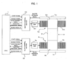
- FIG. 1 is a block diagram showing one embodiment of the present invention. According to this embodiment, position of a magnetic pole is detected using a linear scale for detecting a position and velocity, that is provided to each synchronous linear motor, in tandem control for driving one table serving as an object to be driven by means of two synchronous linear motors.
- the present embodiment includes a numerical control section 1 comprising a numerical controller, a master control section 2m constructing a motor control section for performing drive control on a synchronous linear motor 4m of a master axis, a slave control section 2s constructing a motor control section for performing drive control on a synchronous linear motor 4s of a slave axis, a master amplifier 3m and a slave amplifier 3s.
- the synchronous linear motor 4m of the master axis comprises a stator 5m and a movable member 6m
- the synchronous linear motor 4s of the slave axis comprises a stator 5s and a movable member 6s.
- Either the stator 5m or the movable member 6m, and either the stator 5s or the movable member 6s, are provided with respective magnetic poles, and the others with respective excitation coils.
- the stators 5m and 5s are provided with their respective magnetic poles, while the movable members 6m and 6s with their respective excitation coils.
- linear scales 7m and 7s for detecting positions and velocity of the movable members 6m and 6s are fixed to the master axis and the slave axis, respectively.
- the positions and velocity that are detected by the linear scales 7m and 7s are feedbacked to the master control section 2m and the slave control section 2s, respectively.
- a table 8 fixed to both the movable members 6m and 6s is a table 8 as an object to be driven.
- the numerical control section 1 outputs motion commands to the master control section 2m and the slave control section 2s. Based on the motion commands, the master control section 2m and the slave control section 2s perform the drive control on the synchronous linear motors 4m and 4s by way of the master amplifier 3m and the slave amplifier 3s, respectively, and are synchronized with the table 8 that is fixed to both the movable members 6m and 6s to perform the drive control.
- the numerical control section 1 outputs to the master control section 2m and the slave control section 2s, a magnetic pole detection-start signal for detection of the magnetic pole position and an enable signal that commands to enable a PWM signal to the master amplifier 3m and the slave amplifier 3s.
- the master control section 2m and the slave control section 2s output to the numerical control section 1, a signal indicating midst of the detection of the magnetic pole position, a signal indicating completion of the detection of the magnetic pole position, and even position feedback signals that are feedbacked from the linear scales 7m and 7s.
- the numerical control section 1 controls a process for detecting the magnetic pole position that is carried out by the master control section 2m and the slave control section 2s. Moreover, based on the "midst of detection of the magnetic pole position" signal sent back from the master control section 2m and the slave control section 2s and the position feedback signals, the numerical control section 1 monitors the operation of detecting the magnetic pole position until the "completion of the detection of the magnetic pole position" signal is sent back, and also stops the operation of detecting the magnetic pole position and outputs an alarm or the like when determining that there is an operation abnormality.
- FIG. 2 is a flowchart showing a process for managing and monitoring operation of detecting the magnetic pole position that is implemented by a processor of the numerical control section 1.
- FIG. 2 is so constructed as to be applicable to various systems in which the numerical control section 1 is employed, and is also designed to be able to manage and monitor the detection of the magnetic pole position with or without means (sensor) for detecting the magnetic pole position and even in the case of the tandem control in which a plurality synchronous motors are connected to one another.
- the processor of the numerical control section 1 first determines whether or not a synchronous motor connected to the numerical control section 1 has a dedicated sensor for detecting the magnetic pole position (Step 100). If the synchronous motor has the dedicated sensor, the process is terminated since there is no need for the process for detecting the magnetic pole position. On the contrary, if the synchronous motor has no dedicated sensor for detecting the magnetic pole position, the processor determines whether the tandem control performing the drive control on one object to be driven by using a plurality of synchronous motors is employed or not (Step 101).
- the processor determines the tandem control is employed since the table 8 serving as an object to be driven is driven synchronously by way of two synchronous linear motors 4m and 4s, and thereafter determination is made as to whether the position is detected using one scale or using two or more scales (Step 102). Since there are two linear scales in the embodiment illustrated in FIG. 1, the process advances to Step 110. First of all, the master control section 2m is given a command that an enable signal be ON, whereas the slave control section 2s is given a command that an enable signal be OFF.
- the master control section 2m brings a PWM signal to the master amplifier 3m for driving the synchronous linear motor 4m into an ON state
- the slave control section 2s brings a PWM signal to the slave amplifier 3s into an OFF state.
- the excitation of the synchronous linear motor 4s of the slave axis is released, which brings the synchronous linear motor 4s into a free state that allows free motion.
- the processor of the numerical control section 1 outputs to the master control section 2m a command to start detecting the magnetic pole position (Step 111).
- the processor of the master control section 2m commences a process of operation of detecting the magnetic pole position, that is disclosed in JP 2001-78487A and the like.
- the processor of the numerical control section 1 stays in standby until receiving the "midst of detection of the magnetic pole position" signal from the master control section 2m (Step 112).
- the processor of the numerical control section 1 monitors a position feedback signal transmitted from the master control section 2m and repeatedly makes determinations as to whether the motion within a given time interval is at or under a given value, whether the motion is over a given value, which means an operation abnormality, and whether the detection-completion signal is received (Steps 113 through 115), thereby monitoring the operation of detecting the magnetic pole position.
- the movable member 6m of the synchronous linear motor 4m of the master axis and the movable member 6s of the synchronous linear motor 4s of the slave axis are connected to the table 8, there generates neither torsion nor flexure in a drive transmission structure of the table 8 and the master and slave axes.
- Step 123 of outputting enable OFF to the master control section 2m and outputting an alarm to indicate the alarm of the operation abnormality in detection of the magnetic pole position by way of indicating means or the like.
- the master control section 2m that has received the enable OFF brings the PWM signal into the disable state, brings the movable member 6m into the free state that allows free motion, and terminates the process of operation of detecting the magnetic pole position.
- the processor of the numerical control section 1 gives the master control section 2m a command that the enable signal be OFF and gives the slave control section 2s a command that the enable signal be ON. Accordingly, the master control section 2m brings the PWM signal into the OFF state (disable state), and brings the movable member 6m of the synchronous linear motor 4m of the master axis into the free state that allows free motion. The slave control section 2s brings the PWM signal to the slave amplifier 3s into the ON state, thereby enabling the operation of detecting the magnetic pole position of the synchronous linear motor 4s of the slave axis (Step 116).
- a signal commanding to start detecting the magnetic pole position is outputted to the slave control section 2s (Step 117).
- the slave control section 2s commences the process of operation of detecting the magnetic pole position.
- the processor of the numerical control section 1 receives the "detection midst" signal that is transmitted from the slave control section 2s (Step 120), and repeatedly performs the abnormality-detecting process of Steps 121 through 124 identical to the Steps 112 through 115 until receiving the "completion of detection of the magnetic pole position" signal from the slave control section 2s.
- the process for managing and monitoring the operation of detecting the magnetic pole position is terminated. Also during the operation of detecting the magnetic pole position of the linear motor 4s for driving the slave axis, the movable member 6m of the linear motor 4m of the master axis is in the state where it is freely moved since the linear motor 4m of the master axis is released from excitation in response to the OFF state of the PWM, thus generating neither torsion nor flexure in a machine, such as the table 8 and the like.
- the synchronous motor independently drives the object to be driven, so that it is not required to consider relation with other synchronous motors.
- the enable signal is turned ON to bring the PWM signal to the amplifier for driving the synchronous motor into the ON state (Step 118), and the signal commanding to start detecting the magnetic pole position is turned ON to cause a controlling portion for performing the drive control on the synchronous motor to commence the operation of process for detecting the magnetic pole position (Step 119).
- the processor of the numerical control section 1 carries out the aforementioned process of after the Step 119, thereby monitoring the operation of detecting the magnetic pole position.
- Step 102 there is only one detector for detecting the position and velocity in spite that a plurality of synchronous motors synchronously drive the object to be driven.
- An example of the foregoing would be modification of the embodiment shown in FIG. 1, the modification in which only the master axis is provided with the linear scale 7m, and the slave axis is not provided with the linear scale 7s.
- the linear scale 7m is fixed only to the master axis.
- the enable signal ON is outputted to the master control section 2m and the slave control section 2s.
- the master control section 2m and the slave control section 2s bring the PWM signal into the enable state, thus causing the synchronous linear motors of the master and slave axes to be operational (Step 103).
- the signal commanding to start detecting the magnetic pole position is outputted to the master control section 2m and the slave control section 2s (Step 104).
- the "detection midst" signal is expected to be transmitted from the master control section 2m and the slave control section 2s, and once the signal is received (Step 105), the detection of abnormality and the monitoring process concerning the operation of detecting the magnetic pole position in the Steps 106 through 109 are implemented with respect to both the master and slave axes.
- the detection of abnormality and the monitoring process concerning the operation of detecting the magnetic pole position in the Steps 106 through 109 are equivalent to the process in the Steps 113 through 115 and that of the Steps 121 through 124.
- the enable OFF is outputted to the master control section 2m and the slave control section 2s.
- the PWM signal is made disable, and both the synchronous linear motors 4m and 4s are brought into a free state, which stops the operation of detecting the magnetic pole position.
- an alarm signal is outputted, thereby announcing the occurrence of abnormality in operation of detecting the magnetic pole position.
- the process for managing and monitoring the operation of detecting the magnetic pole position is terminated.
- the process for detecting the magnetic pole position is carried out by synchronously driving the synchronous motors (synchronous linear motors) of the master and slave axes. Therefore, it is required to make adjustments so that there occurs no relative displacement between the magnetic pole positions of the synchronous motors (synchronous linear motors) of the master and slave axes.
- an abnormality in operation of detecting the magnetic pole position is detected on the basis of the position feedback signal that is transmitted from the motor control section (master control section 2m and slave control section 2s)
- the abnormality in operation of detecting the magnetic pole position may be detected by using a velocity feedback signal instead of the position feedback signal.
- the tandem control performed by using the synchronous linear motor is described in the aforementioned embodiment, the present invention is also applicable to a regular rotary synchronous motor.
- the present invention is capable of monitoring the detecting operation and detecting an operation abnormality. Furthermore, even in cases where tandem control is performed, the present invention is capable of normally implementing the operation of detecting the magnetic pole position without generating torsion and flexure in the machine.
Landscapes
- Engineering & Computer Science (AREA)
- Power Engineering (AREA)
- Control Of Linear Motors (AREA)
- Control Of Multiple Motors (AREA)
- Control Of Motors That Do Not Use Commutators (AREA)
Abstract
Description
Claims (7)
- A controller for controlling a synchronous motor having a movable member and a stationary member, one of said movable member and stationary member being provided with magnetic poles and the other thereof provided with excitation coils, said controller comprising:wherein said numerical control section outputs a start command to start detection of the position of the magnetic poles to said motor control section, said motor control section starts detection of the position of the magnetic poles in response to the start command and informs said numerical control section of a state of the detection of the position of the magnetic poles, and said numerical control section determines a normal completion or an abnormality of the detection based on the state of the detection informed by said motor control section.a motor control section for drivingly controlling the synchronous motor and detecting position of the magnetic poles relative to the excitation coils by exciting the excitation coils at a predetermined excitation phase using a sensor for detecting position or velocity of the movable member; anda numerical control section for performing numerical control by issuing commands to said motor control section,
- A controller according to claim 1, wherein said numerical control section stops the detection of the position of the magnetic poles and issues an alarm when an abnormality of the detection is determined.
- A controller according to claim 1, wherein a plurality of motor control sections are provided for respectively drivingly controlling a plurality of synchronous motors for cooperatively driving one driven element, and said numerical control section outputs a start command to one of said plurality of motor control sections to start detection of position of the magnetic poles to enable the detection of the magnetic poles in an associated synchronous motor, and issues commands to the others of said motor control sections to release excitation of associated synchronous motors to eliminate interference with the detection of the position of the magnetic poles by the one motor control section.
- A controller according to claim 1, wherein a plurality of motor control sections are provided for respectively drivingly controlling a plurality of synchronous motors for cooperatively driving one driven element, and said numerical control section issues start commands for starting detections of positions of the magnetic poles to said plurality of motor control sections to enable the detections of the positions of the magnetic poles of associated synchronous motors simultaneously.
- A controller according to claim 4, further comprising a storage device storing a relative displacement between positions of the magnetic poles of the plurality of synchronous motors, wherein said plurality of motor control sections perform the detections of the positions of the magnetic poles using the relative displacement between the positions of the magnetic poles stored in said storage device.
- A controller according to any one of claims 1 through 5, wherein the synchronous motor comprises a linear synchronous motor in which one of the movable member and the stationary member is provided with magnetic poles, and the other thereof provided with excitation coils.
- A controller according to any one of claims 1 through 5, wherein the synchronous motor comprises a rotary synchronous motor having a rotor as the movable member provided with magnetic poles and a stator as the stationary member provided with excitation coils.
Applications Claiming Priority (2)
| Application Number | Priority Date | Filing Date | Title |
|---|---|---|---|
| JP2003021765 | 2003-01-30 | ||
| JP2003021765A JP3689409B2 (en) | 2003-01-30 | 2003-01-30 | Control device |
Publications (3)
| Publication Number | Publication Date |
|---|---|
| EP1443637A2 true EP1443637A2 (en) | 2004-08-04 |
| EP1443637A3 EP1443637A3 (en) | 2006-05-17 |
| EP1443637B1 EP1443637B1 (en) | 2008-12-10 |
Family
ID=32652887
Family Applications (1)
| Application Number | Title | Priority Date | Filing Date |
|---|---|---|---|
| EP04250416A Expired - Lifetime EP1443637B1 (en) | 2003-01-30 | 2004-01-27 | Controller |
Country Status (5)
| Country | Link |
|---|---|
| US (1) | US6876170B2 (en) |
| EP (1) | EP1443637B1 (en) |
| JP (1) | JP3689409B2 (en) |
| CN (1) | CN1269301C (en) |
| DE (1) | DE602004018208D1 (en) |
Families Citing this family (8)
| Publication number | Priority date | Publication date | Assignee | Title |
|---|---|---|---|---|
| KR100985946B1 (en) * | 2006-06-23 | 2010-10-06 | 미쓰비시덴키 가부시키가이샤 | Brushless motor device and method |
| KR101440644B1 (en) | 2006-08-02 | 2014-09-22 | 티에치케이 가부시끼가이샤 | Power branch system and power branch method |
| US7962240B2 (en) | 2007-12-20 | 2011-06-14 | Ge Intelligent Platforms, Inc. | Methods and systems for synchronizing a control signal of a slave follower with a master source |
| JP2009261041A (en) * | 2008-04-11 | 2009-11-05 | Hitachi Ltd | Synchronous motor and method of controlling synchronous motor |
| CN101997463B (en) * | 2010-10-20 | 2012-09-26 | 夷中机科技(北京)有限公司 | Double-direct current brushless motor controller of currency counting machine and control method thereof |
| JP6191665B2 (en) * | 2015-08-21 | 2017-09-06 | 村田機械株式会社 | Moving body |
| CN113711486A (en) * | 2019-04-22 | 2021-11-26 | 三菱电机株式会社 | Motor drive system and motor drive device |
| JP2023135070A (en) * | 2022-03-15 | 2023-09-28 | オムロン株式会社 | servo system |
Family Cites Families (5)
| Publication number | Priority date | Publication date | Assignee | Title |
|---|---|---|---|---|
| DE3120559A1 (en) * | 1981-05-23 | 1982-12-09 | Robert Bosch Gmbh, 7000 Stuttgart | REACTIVE SERVO DRIVE |
| JPH06098585A (en) * | 1992-09-14 | 1994-04-08 | Aisin Aw Co | Motor-driven vehicle |
| JP3042385B2 (en) * | 1995-10-12 | 2000-05-15 | 日本電気株式会社 | Failure detection method and detection device for AC servomotor position detection circuit |
| JP3408468B2 (en) * | 1999-09-07 | 2003-05-19 | ファナック株式会社 | Method for detecting rotor magnetic pole position of synchronous motor |
| JP2002190695A (en) * | 2000-12-22 | 2002-07-05 | Juki Corp | XY moving device and electronic component mounting device using XY moving device |
-
2003
- 2003-01-30 JP JP2003021765A patent/JP3689409B2/en not_active Expired - Fee Related
-
2004
- 2004-01-27 EP EP04250416A patent/EP1443637B1/en not_active Expired - Lifetime
- 2004-01-27 DE DE602004018208T patent/DE602004018208D1/en not_active Expired - Lifetime
- 2004-01-28 US US10/765,190 patent/US6876170B2/en not_active Expired - Lifetime
- 2004-01-30 CN CNB2004100393577A patent/CN1269301C/en not_active Expired - Fee Related
Also Published As
| Publication number | Publication date |
|---|---|
| US20040183497A1 (en) | 2004-09-23 |
| CN1269301C (en) | 2006-08-09 |
| JP2004236433A (en) | 2004-08-19 |
| US6876170B2 (en) | 2005-04-05 |
| EP1443637B1 (en) | 2008-12-10 |
| DE602004018208D1 (en) | 2009-01-22 |
| JP3689409B2 (en) | 2005-08-31 |
| CN1520023A (en) | 2004-08-11 |
| EP1443637A3 (en) | 2006-05-17 |
Similar Documents
| Publication | Publication Date | Title |
|---|---|---|
| US6252367B1 (en) | Servo controller | |
| US9110451B2 (en) | Motor control system and safety monitoring system therefor | |
| US20140265960A1 (en) | Control system for synchronous motor including abnormality detection and diagnosis function | |
| US6876170B2 (en) | Controller | |
| CN109581970B (en) | Parameter determination support device | |
| CN110376970B (en) | Parameter determination support device and computer-readable medium having program recorded thereon | |
| US10527676B2 (en) | Abnormality diagnosing device and abnormality diagnosing method | |
| US12301064B2 (en) | Method for determining an air gap between a transport rotor and a stator segment aided by an automation device | |
| CN110161974B (en) | Parameter determination support device and computer-readable medium having program recorded thereon | |
| JP3220587B2 (en) | Numerical controller with torque ripple analysis function | |
| CN113067524A (en) | Position information processing method of hub servo motor | |
| EP0667203A1 (en) | System for controlling tension of wire | |
| JP4206374B2 (en) | Synchronous motor control device and initial phase setting method thereof | |
| CN110161971B (en) | Parameter determination support device and computer-readable medium having program recorded thereon | |
| JP3042385B2 (en) | Failure detection method and detection device for AC servomotor position detection circuit | |
| JPH06351278A (en) | Vector controller for induction motor | |
| CN110161844B (en) | Parameter determination support device and computer-readable medium having program recorded thereon | |
| JP4087374B2 (en) | Numerical controller with load torque monitoring function | |
| JP2007156510A (en) | Numerical control system | |
| JP6705782B2 (en) | Synchronous motor magnetic pole position detection device and synchronous motor magnetic pole position detection method | |
| JP2007506397A (en) | Method and apparatus for controlling motor | |
| JP2016056548A (en) | Automatic door device | |
| JPH0772045B2 (en) | Electric machine controller for paper machine | |
| JPH11267900A (en) | Monitoring device of stopping motion in servo press | |
| KR20160068677A (en) | Method for ascertaining a commutation angle |
Legal Events
| Date | Code | Title | Description |
|---|---|---|---|
| PUAI | Public reference made under article 153(3) epc to a published international application that has entered the european phase |
Free format text: ORIGINAL CODE: 0009012 |
|
| AK | Designated contracting states |
Kind code of ref document: A2 Designated state(s): AT BE BG CH CY CZ DE DK EE ES FI FR GB GR HU IE IT LI LU MC NL PT RO SE SI SK TR |
|
| AX | Request for extension of the european patent |
Extension state: AL LT LV MK |
|
| PUAL | Search report despatched |
Free format text: ORIGINAL CODE: 0009013 |
|
| AK | Designated contracting states |
Kind code of ref document: A3 Designated state(s): AT BE BG CH CY CZ DE DK EE ES FI FR GB GR HU IE IT LI LU MC NL PT RO SE SI SK TR |
|
| AX | Request for extension of the european patent |
Extension state: AL LT LV MK |
|
| RIC1 | Information provided on ipc code assigned before grant |
Ipc: H02P 5/46 20060101ALI20060329BHEP Ipc: H02P 6/20 20060101AFI20060329BHEP |
|
| 17P | Request for examination filed |
Effective date: 20061113 |
|
| AKX | Designation fees paid |
Designated state(s): DE |
|
| 17Q | First examination report despatched |
Effective date: 20070312 |
|
| GRAP | Despatch of communication of intention to grant a patent |
Free format text: ORIGINAL CODE: EPIDOSNIGR1 |
|
| GRAS | Grant fee paid |
Free format text: ORIGINAL CODE: EPIDOSNIGR3 |
|
| GRAS | Grant fee paid |
Free format text: ORIGINAL CODE: EPIDOSNIGR3 |
|
| GRAA | (expected) grant |
Free format text: ORIGINAL CODE: 0009210 |
|
| AK | Designated contracting states |
Kind code of ref document: B1 Designated state(s): DE |
|
| REF | Corresponds to: |
Ref document number: 602004018208 Country of ref document: DE Date of ref document: 20090122 Kind code of ref document: P |
|
| PLBE | No opposition filed within time limit |
Free format text: ORIGINAL CODE: 0009261 |
|
| STAA | Information on the status of an ep patent application or granted ep patent |
Free format text: STATUS: NO OPPOSITION FILED WITHIN TIME LIMIT |
|
| 26N | No opposition filed |
Effective date: 20090911 |
|
| REG | Reference to a national code |
Ref country code: DE Ref legal event code: R082 Ref document number: 602004018208 Country of ref document: DE Representative=s name: HL KEMPNER PATENTANWALT, RECHTSANWALT, SOLICIT, DE |
|
| PGFP | Annual fee paid to national office [announced via postgrant information from national office to epo] |
Ref country code: DE Payment date: 20210112 Year of fee payment: 18 |
|
| REG | Reference to a national code |
Ref country code: DE Ref legal event code: R119 Ref document number: 602004018208 Country of ref document: DE |
|
| PG25 | Lapsed in a contracting state [announced via postgrant information from national office to epo] |
Ref country code: DE Free format text: LAPSE BECAUSE OF NON-PAYMENT OF DUE FEES Effective date: 20220802 |