EP1443608A2 - Connector door having overtravel stops - Google Patents
Connector door having overtravel stops Download PDFInfo
- Publication number
- EP1443608A2 EP1443608A2 EP04250150A EP04250150A EP1443608A2 EP 1443608 A2 EP1443608 A2 EP 1443608A2 EP 04250150 A EP04250150 A EP 04250150A EP 04250150 A EP04250150 A EP 04250150A EP 1443608 A2 EP1443608 A2 EP 1443608A2
- Authority
- EP
- European Patent Office
- Prior art keywords
- plug
- chamber
- jack
- door
- orifice
- Prior art date
- Legal status (The legal status is an assumption and is not a legal conclusion. Google has not performed a legal analysis and makes no representation as to the accuracy of the status listed.)
- Withdrawn
Links
Images



Classifications
-
- H—ELECTRICITY
- H01—ELECTRIC ELEMENTS
- H01R—ELECTRICALLY-CONDUCTIVE CONNECTIONS; STRUCTURAL ASSOCIATIONS OF A PLURALITY OF MUTUALLY-INSULATED ELECTRICAL CONNECTING ELEMENTS; COUPLING DEVICES; CURRENT COLLECTORS
- H01R13/00—Details of coupling devices of the kinds covered by groups H01R12/70 or H01R24/00 - H01R33/00
- H01R13/44—Means for preventing access to live contacts
- H01R13/447—Shutter or cover plate
- H01R13/453—Shutter or cover plate opened by engagement of counterpart
- H01R13/4536—Inwardly pivoting shutter
-
- H—ELECTRICITY
- H01—ELECTRIC ELEMENTS
- H01R—ELECTRICALLY-CONDUCTIVE CONNECTIONS; STRUCTURAL ASSOCIATIONS OF A PLURALITY OF MUTUALLY-INSULATED ELECTRICAL CONNECTING ELEMENTS; COUPLING DEVICES; CURRENT COLLECTORS
- H01R24/00—Two-part coupling devices, or either of their cooperating parts, characterised by their overall structure
- H01R24/60—Contacts spaced along planar side wall transverse to longitudinal axis of engagement
- H01R24/62—Sliding engagements with one side only, e.g. modular jack coupling devices
Definitions
- U.S. Patent No. 6,004,043 discloses, for example, a shuttered fiber optic receptacle wherein an inclined planar shutter near the mouth of the receptacle helps protect against contamination while, due to its inclined state, avoiding the reflection of light back into the fiber optic core during mating.
- U.S. Patent No. 6,004,043 discloses, for example, a shuttered fiber optic receptacle wherein an inclined planar shutter near the mouth of the receptacle helps protect against contamination while, due to its inclined state, avoiding the reflection of light back into the fiber optic core during mating.
- U.S. Patent No. 6,108,482 discloses a fiber optic connector receptacle having a one-piece shutter with a recessed area for protecting the end of fiber being inserted therein. As fiber ends are commonly pre-polished, such damage may particularly thwart an expensive effort to provide hardware capable of reliable, high-performance communication.
- the point of full insertion of the plug may be marked by the electrical contacts (or a fiber end) abruptly contacting a bulkhead, stop, or housing back wall that may damage the contact (or fiber end) and thereby degrade performance of the connector. Even an abrupt mating with other electrical contacts may cause undesirable effects.
- a connector able to deter the passage of foreign debris into the connective environment while simultaneously preventing damage to the connective apparatus, such as extending terminals, throughout the insertion path of the inserted plug.
- the jack includes a pivotable prebiased door that includes a projecting portion for limiting the extent of insertion of the plug into the chamber of the jack.
- a pivotable prebiased door that includes a projecting portion for limiting the extent of insertion of the plug into the chamber of the jack.
- a jack for receiving and connecting with a compatible plug
- the jack including a housing having a plug-receiving chamber therein, the housing having an orifice through which the plug is insertable into and removable from the chamber, and a pivotable prebiased door having a closed position generally disposed over the orifice when the plug is not disposed within the chamber and an open position not generally disposed over the orifice when the plug is disposed within the chamber, the door including a projecting portion for limiting the extent of insertion of the plug into the chamber.
- a method of assembling a jack for receiving and electrically connecting with a compatible plug including the steps of providing an integrally formed housing having a pair of opposed top and bottom walls and a pair of opposed side walls extending between the top and bottom walls and having a forwardly facing orifice and rearwardly facing opening defined by the top, bottom, and side walls, providing a sled member having accessible electrical conductors proximate a forward end thereof for cooperatively engaging electrical conductors on the compatible plug when the plug is received in the jack, inserting at least the forward end of the sled member into the rearwardly facing opening proximate the bottom wall, providing a door having a pivot bar and a torsional spring mounted thereto, inserting the door into the housing through the rearwardly facing opening between the sled member and the top wall and into a position wherein the door may be biased by the spring to substantially cover the forwardly facing orifice, providing a rear bulkhead member, and inserting the rear bulkhead member
- a jack for receiving and connecting with a compatible plug, the plug including a depressible latch
- the jack including a housing including a pair of opposed top and bottom walls, a pair of opposed side walls extending between the top and bottom walls, and a rear bulkhead, the top, bottom, side walls and the rear bulkhead substantially defining a chamber having a forwardly facing orifice through which the plug is insertable into and removable from the chamber, the rear bulkhead not being integrally formed with any of the top, bottom, and side walls, and a pivotable prebiased door having a torsional spring mounted thereto and having a closed position generally disposed over and flush with the orifice when the plug is not disposed within the chamber to substantially prevent foreign matter from entering the chamber and an open position not generally disposed over the orifice when the plug is disposed within the chamber, the door including a projecting portion for limiting the extent of insertion of the plug into the chamber and including structure for cooperatively engaging the latch for facilitating latching the plug into
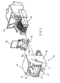
- the connector takes the form of a TX-style jack 10 that includes a housing 12 having a plug-receiving chamber therein for receiving a cooperatively engageable TX-style plug 50 and thereby connecting with the plug, as seen in Figs. 1 and 2.
- the inventive connector could alternatively take the form of a different type of electrical connector, or even a fiber optic connector.
- the housing 12 includes a top wall 14, a bottom wall 16, and a pair of side walls 18 that cooperatively define a plug-receiving chamber 20 therebetween.
- the front of the housing 12 includes an orifice 22 for receiving the appropriately configured plug 50 therethrough, the front may also preferably include a partial front wall 24 that extends inwardly from one or more of the top, bottom and side walls.
- the rear of the housing 12 also has an opening 26, as easily seen in Figs. 3 and 4, so that a door 28 and sled 30 may be inserted therethrough and into the plug-receiving chamber 20.
- Fig. 2 shows the intermatability and alignment between the plug and jack.
- the plug 50 is a standard TX plug having a latch 52 thereon for releasably securing the plug within the jack when inserted therein.
- the latch 52 depressibly fits through a notch 32 coming off the orifice 22 in the partial front wall 24.
- Fig. 3 explodedly shows the door 28 being disposable within the housing 12 in front of the sled 30 and bulkhead 35.
- the door 28 includes a torsional spring 34 for supplying bias thereto.
- the torsion spring when the torsion spring is rotated around the shaft 29 of the door 28 in the direction of the arrow shown (clockwise when viewed from the right side of the jack) so that the door may be inserted into the rear opening 26 of the housing 12, this applies pre-bias to the door 28 such that the door would be urged in a similar direction around the door shaft 29.
- the door is installed into the housing by pushing opposite ends 31 of the shaft 29 past the ramped shaft stops 33.
- the sled 30 When the sled 30 is fully inserted, the sled preferably rests entirely below the door 28, and the contacts on the sled preferably do not impede the ability of the door to rotate about its shaft 29 to abut, or nearly abut, the underside of the top wall 14 of the housing 12.
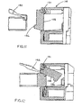
- the front face 54 of the plug 50 or the front portion 56 of the latch 52 first contacts the door 28 that is pre-biased forwardly to substantially close the front orifice 22 of the housing 12.
- the contact force rotates the door 28 (counterclockwise when seen from right side view of the figures) against the bias of the torsion spring 34 that is wrapped around the shaft 29 and flush, or nearly flush, against the underside of the top wall 14 of the housing 12.
- the plug and door are configured, depending upon whether and what type of electrical contacts, or even fiber optic fibers, are present, such that the electrical contacts (or fibers) are spared any of the contact force between the plug and door when the plug is being inserted.
- the electrical contacts of the plug would be near the bottom of the plug, while the contact with the door of the jack would occur in the upper portion of the front face 54 of the plug, or possibly on the front portion 56 of the latch.
- the signal transmission medium i.e., the set of contacts
- the door 28 includes forwardly extending projections 36.
- one or more of the projections 36 is/are the first portion(s) of the door contacted by the plug 50. This is one means by which contact forces being applied to the transmission medium during plug insertion may be averted.
- the extent of insertion is limited by at least one of the projections 36 on the door, with the projections contacting the plug in a manner so as to apply no contact forces to the signal transmission medium, i.e., the electrical contacts.
- the transmission medium is protected both upon the plug initially engaging the door as it is first entering the jack (due to the recessed portion of the door) and upon full insertion into the jack.
- This protection at full insertion prevents the bulkhead 35 or other structure within the jack from applying contact forces to the signal transmission medium as the maximum extent of plug insertion is reached. Protection throughout the insertion process can be critical to the performance of the transmission medium. Overtravel stops extending forwardly from the front of the door are provided to achieve such protection. Additionally, the door itself inhibits the entry of foreign debris into the connector, so the door having overtravel stops prevents the connector from failing to achieve high performance in two ways.
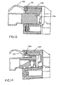
- jack 110 includes a similarly biasable door 128 that also includes forwardly directed projections 136 on the front thereof. The projections function similarly to those of the previously described embodiment(s).
- the plug latch 152 includes a truncated portion 154 that latches into the latch-receiving portion 127 of the door 128 to releasably retain the plug within the jack 110. Such an arrangement may provide space savings within the connector.
Landscapes
- Connector Housings Or Holding Contact Members (AREA)
- Mechanical Coupling Of Light Guides (AREA)
Abstract
Description
Claims (10)
- A jack for receiving and connecting with a compatible plug, said jack comprising:a housing having a plug-receiving chamber therein, said housing having an orifice through which said plug is insertable into and removable from said chamber; anda pivotable prebiased door having a closed position generally disposed over said orifice when said plug is not disposed within said chamber and an open position not generally disposed over said orifice when said plug is disposed within said chamber, said door including a projecting portion for limiting the extent of insertion of said plug into said chamber.
- A jack in accordance with claim 1 wherein said door is prebiased by a torsional spring.
- A jack in accordance with claim 1 wherein said cover is generally flush with said orifice when said plug is not disposed within said chamber, whereby said cover substantially prevents foreign matter from entering said chamber.
- A jack in accordance with claim 1 wherein said housing includes a pair of opposed top and bottom walls, a pair of opposed side walls extending between said top and bottom walls, and a rear bulkhead generally opposing said orifice, said top, bottom, side walls and said rear bulkhead substantially defining said chamber, said rear bulkhead not being integrally formed with any of said top, bottom, and side walls.
- A jack in accordance with claim 1 wherein said housing includes a protective member extending forwardly therefrom at least partially adjacent said orifice, said protective member extending forwardly beyond said projecting portion, and preferably
wherein said protective member includes a guide-in portion for facilitating insertion of said plug through said orifice. - A jack in accordance with claim 1 wherein said plug includes a depressible latch and said door includes structure for cooperatively engaging said latch for facilitating latching said plug into said chamber when said plug is inserted sufficiently far into said chamber and for facilitating unlatched removal of said plug from said chamber upon depression of said latch.
- A jack in accordance with claim 1 wherein said prebiased door is biased against said plug when said plug is disposed within said chamber to facilitate electrical connection between said plug and said jack.
- A method of assembling a jack for receiving and electrically connecting with a compatible plug, said method comprising the steps of:providing an integrally formed housing having a pair of opposed top and bottom walls and a pair of opposed side walls extending between said top and bottom walls and having a forwardly facing defined by said top, bottom, and side walls;providing electrical conductors proximate a forward end thereof for cooperatively engaging electrical conductors on said compatible plug when said plug is received in said jack; andproviding a door having a pivot bar and a torsional spring mounted thereto;inserting said door into said housing and into a position wherein said door may be biased by said spring to substantially cover said forwardly facing orifice.
- A jack for receiving and connecting with a compatible plug, said plug including a depressible latch, said jack comprising:a housing including a pair of opposed top and bottom walls, a pair of opposed side walls extending between said top and bottom walls, and a rear bulkhead, said top, bottom, side walls and said rear bulkhead substantially defining a chamber having a forwardly facing orifice through which said plug is insertable into and removable from said chamber, said rear bulkhead not being integrally formed with any of said top, bottom, and side walls; anda pivotable prebiased door having a torsional spring mounted thereto and having a closed position generally disposed over and flush with said orifice when said plug is not disposed within said chamber to substantially prevent foreign matter from entering said chamber and an open position not generally disposed over said orifice when said plug is disposed within said chamber;said door including a projecting portion for limiting the extent of insertion of said plug into said chamber and including structure for cooperatively engaging said latch for facilitating latching said plug into said chamber when said plug is inserted sufficiently far into said chamber and for facilitating unlatched removal of said plug from said chamber upon depression of said latch; andsaid housing including a protective member extending forwardly therefrom at least partially adjacent said orifice, said protective member extending forwardly beyond said projecting portion.
- A jack in accordance with claim 9 wherein said protective member includes a guide-in portion for facilitating insertion of said plug through said orifice, and preferably
wherein said prebiased door is biased against said plug when said plug is disposed within said chamber to facilitate electrical connection between said plug and said jack.
Applications Claiming Priority (2)
| Application Number | Priority Date | Filing Date | Title |
|---|---|---|---|
| US347214 | 1999-07-02 | ||
| US10/347,214 US6869297B2 (en) | 2003-01-17 | 2003-01-17 | Connector door having overtravel stops |
Publications (2)
| Publication Number | Publication Date |
|---|---|
| EP1443608A2 true EP1443608A2 (en) | 2004-08-04 |
| EP1443608A3 EP1443608A3 (en) | 2008-05-07 |
Family
ID=32655481
Family Applications (1)
| Application Number | Title | Priority Date | Filing Date |
|---|---|---|---|
| EP04250150A Withdrawn EP1443608A3 (en) | 2003-01-17 | 2004-01-14 | Connector door having overtravel stops |
Country Status (4)
| Country | Link |
|---|---|
| US (2) | US6869297B2 (en) |
| EP (1) | EP1443608A3 (en) |
| JP (1) | JP2004228079A (en) |
| CN (1) | CN1519992B (en) |
Cited By (11)
| Publication number | Priority date | Publication date | Assignee | Title |
|---|---|---|---|---|
| WO2016156643A1 (en) * | 2015-03-27 | 2016-10-06 | De Dios Martín Longinos | Cover assembly for a jack receptacle |
| EP3132510A4 (en) * | 2014-04-14 | 2017-09-27 | Leviton Manufacturing Company, Inc. | Communication outlet with shutter mechanism and wire manager |
| US9831606B2 (en) | 2015-10-14 | 2017-11-28 | Leviton Manufacturing Co., Inc. | Communication connector |
| US9859663B2 (en) | 2013-03-15 | 2018-01-02 | Leviton Manufacturing Co., Inc. | Communications connector system |
| USD818469S1 (en) | 2014-06-19 | 2018-05-22 | Leviton Manufacturing Co., Inc. | Communication outlet |
| US10135207B2 (en) | 2016-01-31 | 2018-11-20 | Leviton Manufacturing Co., Inc. | High-speed data communications connector |
| US11342718B2 (en) | 2015-03-27 | 2022-05-24 | CommScope Connectivity Spain, S.L. | Latch for telecommunications connector |
| US11356752B2 (en) | 2017-11-10 | 2022-06-07 | Commscope Technologies Llc | Telecommunications panel with grounding wire |
| US11356751B2 (en) | 2017-06-19 | 2022-06-07 | Commscope Technologies Llc | High density bezel for patch panel |
| US11367985B2 (en) | 2016-08-15 | 2022-06-21 | Commscope Technologies Llc | Connector assembly with grounding |
| US11509105B2 (en) | 2015-03-20 | 2022-11-22 | CommScope Connectivity Spain, S.L. | Connector with separable lacing fixture |
Families Citing this family (35)
| Publication number | Priority date | Publication date | Assignee | Title |
|---|---|---|---|---|
| US6869297B2 (en) * | 2003-01-17 | 2005-03-22 | Panduit Corp. | Connector door having overtravel stops |
| MY137176A (en) * | 2003-09-11 | 2009-01-30 | Clipsal Australia Pty Ltd | Shuttered electrical connecter socket |
| JP2005318227A (en) * | 2004-04-28 | 2005-11-10 | Matsushita Electric Ind Co Ltd | Electroacoustic transducer and electronic device using the same |
| WO2005115047A1 (en) * | 2004-05-20 | 2005-12-01 | Matsushita Electric Industrial Co., Ltd. | Portable electronic device |
| KR100663486B1 (en) * | 2004-06-24 | 2007-01-02 | 삼성전자주식회사 | Interface connector cover switchgear of mobile terminal |
| JP4196114B2 (en) * | 2004-07-01 | 2008-12-17 | パナソニック株式会社 | Electroacoustic transducer and electronic device using the same |
| US7001204B1 (en) * | 2005-01-12 | 2006-02-21 | Jyh Eng Technology Co., Ltd. | Transmitting jack with prong-type conductive pieces |
| FR2897230B1 (en) * | 2006-02-03 | 2008-04-04 | Legrand France | PERFECTIONAL SHUTTER DEVICE WITH MOBILE SHUTTER |
| US7744388B2 (en) | 2007-07-10 | 2010-06-29 | Adc Gmbh | Electrical connector having a protective door element |
| AU316095S (en) | 2007-07-10 | 2007-09-12 | Tyco Electronics Services Gmbh | Electrical connector |
| AU316096S (en) | 2007-07-10 | 2007-09-12 | Tyco Electronics Services Gmbh | Electrical connector |
| TWM329781U (en) * | 2007-07-24 | 2008-04-01 | Hon Hai Prec Ind Co Ltd | Optical fiber connector |
| ES2372260T3 (en) * | 2009-02-27 | 2012-01-17 | Tyco Electronics Amp España S.A. | IMPROVED PLUG AND PLUG. |
| TWI379468B (en) * | 2009-03-25 | 2012-12-11 | Protek Shanghai Ltd | Electrical connector socket and portable electrical device using the same |
| JP2010281910A (en) * | 2009-06-02 | 2010-12-16 | Japan Aviation Electronics Industry Ltd | Optical connector device |
| US20110221601A1 (en) * | 2010-03-12 | 2011-09-15 | Jerry Aguren | Detecting Engagement Conditions Of A Fiber Optic Connector |
| US8057249B1 (en) * | 2010-07-19 | 2011-11-15 | Tyco Electronics Corporation | Electrical connector with slim-line cap |
| JP5066620B2 (en) * | 2011-03-25 | 2012-11-07 | 日本航空電子工業株式会社 | Optical connector device |
| US9360648B2 (en) | 2011-09-16 | 2016-06-07 | Commscope Technologies Llc | Systems and methods for the management of fiber optic cables |
| US8805153B2 (en) | 2011-09-16 | 2014-08-12 | Adc Telecommunications, Inc. | Systems and methods for the management of fiber optic cables |
| US8764465B2 (en) * | 2012-08-22 | 2014-07-01 | Wistron Corporation | Connector mechanism having a pivotably disposed cover and a resilient component engaging the cover |
| US8827726B2 (en) * | 2012-12-14 | 2014-09-09 | Energy Full Electronics | Electric connector assembly |
| US9627827B2 (en) | 2014-04-14 | 2017-04-18 | Leviton Manufacturing Co., Inc. | Communication outlet with shutter mechanism and wire manager |
| US9515437B2 (en) | 2014-04-14 | 2016-12-06 | Leviton Manufacturing Co., Inc. | Communication outlet with shutter mechanism and wire manager |
| US9419362B2 (en) * | 2014-08-06 | 2016-08-16 | Foxconn Interconnect Technology Limited | Electrical receptacle connector |
| US9874702B2 (en) * | 2014-10-29 | 2018-01-23 | Hewlett Packard Enterprise Development Lp | Optical connector assembly apparatus |
| KR102367973B1 (en) * | 2015-02-06 | 2022-02-25 | 코닝 리서치 앤드 디벨롭먼트 코포레이션 | Connecting device for identifying lines |
| EP3387715B1 (en) * | 2015-12-08 | 2021-05-12 | Panduit Corp. | Rj45 shuttered jacks and related communication systems |
| FR3072509B1 (en) * | 2017-10-18 | 2022-06-10 | Schneider Electric Ind Sas | FEMALE CONNECTOR COMPRISING AN OPENING FOR ENGAGEMENT OF A MALE CONNECTOR EQUIPPED WITH A COVERING DOOR FOR THIS OPENING |
| JP6861612B2 (en) * | 2017-11-08 | 2021-04-21 | 株式会社Pfu | Electronics |
| WO2020003136A1 (en) * | 2018-06-29 | 2020-01-02 | 3M Innovative Properties Company | Connector with pivoting magnetic door |
| CN111817065B (en) * | 2020-06-18 | 2021-09-10 | 宁波公牛电器有限公司 | Information socket |
| EP4204875A1 (en) | 2020-08-26 | 2023-07-05 | Afl Ig Llc | Adaptor and method for mating a fiber optic connector |
| US11733745B2 (en) * | 2021-07-20 | 2023-08-22 | Dell Products L.P. | Port protection system |
| US12051872B2 (en) * | 2021-12-17 | 2024-07-30 | Hsing Chau Industrial Co., Ltd. | Shuttered keystone jack assembly |
Family Cites Families (38)
| Publication number | Priority date | Publication date | Assignee | Title |
|---|---|---|---|---|
| US3800328A (en) * | 1972-04-28 | 1974-03-26 | Motorola Inc | Two-way door assembly for a cassette tape player |
| US4779950A (en) | 1984-04-03 | 1988-10-25 | Thomas & Betts Corporation | Connection apparatus for optical fibers |
| US4712861A (en) | 1985-02-07 | 1987-12-15 | Northern Telecom Limited | Two-channel hermaphroditic fiber connector |
| JPS62172671A (en) * | 1986-01-27 | 1987-07-29 | 松下電工株式会社 | Connectiong jack for telephone line |
| US4666225A (en) | 1986-02-19 | 1987-05-19 | Siecor Corporation | Electrical jack |
| KR900004629B1 (en) | 1986-06-20 | 1990-06-30 | 미쓰비시전기 주식회사 | Electrostatic-proof door of cassette tape player |
| US4960317A (en) | 1988-08-23 | 1990-10-02 | Amp Incorporated | Wall outlet for a fiber optic connector assembly |
| JPH0714575U (en) * | 1991-12-27 | 1995-03-10 | センチュリーメディカル株式会社 | Connector locking mechanism |
| US5547401A (en) | 1992-04-08 | 1996-08-20 | Megahertz Corporation | Media connector interface for use with a thin-architecture communications card |
| US5302141A (en) * | 1992-11-23 | 1994-04-12 | Cole Hersee Company | Compatible trailer connection |
| US5506922A (en) | 1994-08-01 | 1996-04-09 | Molex Incorporated | Fiber optic component assembly with a movable protective shield |
| CA2130410C (en) * | 1994-08-18 | 2001-12-04 | Albert John Kerklaan | Retractable expandable jack |
| JPH08138785A (en) | 1994-11-10 | 1996-05-31 | Yazaki Corp | Connector with shutter mechanism |
| JP3230955B2 (en) * | 1995-08-29 | 2001-11-19 | 矢崎総業株式会社 | Connector with protective cover |
| US5769647A (en) | 1995-11-22 | 1998-06-23 | The Siemon Company | Modular outlet employing a door assembly |
| US5800188A (en) * | 1996-02-09 | 1998-09-01 | Joseph Pollak Corporation | Direct connect trailer tow interconnector |
| US5956444A (en) * | 1997-02-13 | 1999-09-21 | Amphenol Corporation | Radiation absorbing shield for fiber optic systems |
| US5873744A (en) * | 1997-02-18 | 1999-02-23 | Ramos, Jr.; Phillip M. | Electrical connector assembly |
| JP3278047B2 (en) * | 1997-08-18 | 2002-04-30 | 住友電装株式会社 | connector |
| TW343739U (en) * | 1997-09-13 | 1998-10-21 | Transian Technology Co Ltd | An optic adapter with protection feature |
| US6004043A (en) | 1997-12-19 | 1999-12-21 | The Whitaker Corporation | Shuttered connector receptacle |
| US6081647A (en) * | 1998-01-05 | 2000-06-27 | Molex Incorporated | Fiber optic connector receptacle |
| US6154597A (en) | 1998-01-05 | 2000-11-28 | Molex Incorporated | Fiber optic termination system including a fiber optic connector assembly and method of fabricating same |
| US6108482A (en) | 1998-01-14 | 2000-08-22 | Molex Incorporated | Fiber optic connector receptacle |
| GB2335314B (en) | 1998-03-14 | 2002-04-03 | Hawke Cable Glands Ltd | Electrical connectors |
| US5964600A (en) | 1998-06-05 | 1999-10-12 | Molex Incorporated | Shuttered electrical connector |
| US6106335A (en) | 1998-06-05 | 2000-08-22 | Molex Incorporated | Crosstalk correction in electrical connectors |
| US6130977A (en) * | 1998-07-17 | 2000-10-10 | Siecor Operations, Llc | Fiber optic connector sleeve having positioning ribs |
| US6292564B1 (en) * | 1999-02-09 | 2001-09-18 | Avaya Technology Corp. | Modular jack protective cover for harsh environmental conditions |
| US6287133B1 (en) * | 2000-03-08 | 2001-09-11 | Ming Fortune Industry Co., Ltd. | Dustproof cover |
| US6685362B2 (en) * | 2000-03-24 | 2004-02-03 | Tyco Electronics Corporation | Shielded adapter assembly |
| US6354746B1 (en) * | 2000-05-22 | 2002-03-12 | Fiberon Technologies, Inc. | Plug and receptacle connection for optical fiber cables |
| TW464086U (en) * | 2000-11-15 | 2001-11-11 | Hon Hai Prec Ind Co Ltd | Electric connector for socket |
| JP4588206B2 (en) * | 2000-12-18 | 2010-11-24 | 日置電機株式会社 | Connection structure between electrical equipment and connection cord |
| US6595696B1 (en) * | 2001-03-14 | 2003-07-22 | Amphenol Corporation | Internal shutter for optical adapters |
| TW493760U (en) * | 2001-11-30 | 2002-07-01 | Hon Hai Prec Ind Co Ltd | Optical fiber connector |
| TW523197U (en) * | 2001-12-26 | 2003-03-01 | Hon Hai Prec Ind Co Ltd | Electronic card connector |
| US6869297B2 (en) * | 2003-01-17 | 2005-03-22 | Panduit Corp. | Connector door having overtravel stops |
-
2003
- 2003-01-17 US US10/347,214 patent/US6869297B2/en not_active Expired - Fee Related
-
2004
- 2004-01-14 EP EP04250150A patent/EP1443608A3/en not_active Withdrawn
- 2004-01-16 JP JP2004008585A patent/JP2004228079A/en active Pending
- 2004-01-16 CN CN200410002741.XA patent/CN1519992B/en not_active Expired - Fee Related
-
2005
- 2005-02-10 US US11/054,761 patent/US20050152536A1/en not_active Abandoned
Cited By (20)
| Publication number | Priority date | Publication date | Assignee | Title |
|---|---|---|---|---|
| US9859663B2 (en) | 2013-03-15 | 2018-01-02 | Leviton Manufacturing Co., Inc. | Communications connector system |
| EP3132510A4 (en) * | 2014-04-14 | 2017-09-27 | Leviton Manufacturing Company, Inc. | Communication outlet with shutter mechanism and wire manager |
| EP4329110A3 (en) * | 2014-04-14 | 2024-07-24 | Leviton Manufacturing Company, Inc. | Communication outlet with shutter mechanism and wire manager |
| USD848430S1 (en) | 2014-06-19 | 2019-05-14 | Leviton Manufacturing Co., Inc. | Communication outlet |
| USD818469S1 (en) | 2014-06-19 | 2018-05-22 | Leviton Manufacturing Co., Inc. | Communication outlet |
| USD901509S1 (en) | 2014-06-19 | 2020-11-10 | Leviton Manufacturing Co., Inc. | Communication outlet |
| US11509105B2 (en) | 2015-03-20 | 2022-11-22 | CommScope Connectivity Spain, S.L. | Connector with separable lacing fixture |
| WO2016156643A1 (en) * | 2015-03-27 | 2016-10-06 | De Dios Martín Longinos | Cover assembly for a jack receptacle |
| US10522939B2 (en) | 2015-03-27 | 2019-12-31 | CommScope Connectivity Spain, S.L. | Cover assembly for a telecommunications connector |
| US10958012B2 (en) | 2015-03-27 | 2021-03-23 | CommScope Connectivity Spain, S.L. | Cover assembly for a telecommunications connector |
| US11342718B2 (en) | 2015-03-27 | 2022-05-24 | CommScope Connectivity Spain, S.L. | Latch for telecommunications connector |
| US12355196B2 (en) | 2015-03-27 | 2025-07-08 | CommScope Connectivity Spain, S.L. | Latch for telecommunications connector |
| US12206205B2 (en) | 2015-03-27 | 2025-01-21 | CommScope Connectivity Spain, S.L. | Cover assembly for a telecommunications connector |
| US9831606B2 (en) | 2015-10-14 | 2017-11-28 | Leviton Manufacturing Co., Inc. | Communication connector |
| US10135207B2 (en) | 2016-01-31 | 2018-11-20 | Leviton Manufacturing Co., Inc. | High-speed data communications connector |
| US11367985B2 (en) | 2016-08-15 | 2022-06-21 | Commscope Technologies Llc | Connector assembly with grounding |
| US12149032B2 (en) | 2016-08-15 | 2024-11-19 | Commscope Technologies Llc | Connector assembly with grounding |
| US11838700B2 (en) | 2017-06-19 | 2023-12-05 | Commscope Technologies Llc | High density bezel for patch panel |
| US11356751B2 (en) | 2017-06-19 | 2022-06-07 | Commscope Technologies Llc | High density bezel for patch panel |
| US11356752B2 (en) | 2017-11-10 | 2022-06-07 | Commscope Technologies Llc | Telecommunications panel with grounding wire |
Also Published As
| Publication number | Publication date |
|---|---|
| US6869297B2 (en) | 2005-03-22 |
| US20040142589A1 (en) | 2004-07-22 |
| JP2004228079A (en) | 2004-08-12 |
| CN1519992B (en) | 2010-05-05 |
| EP1443608A3 (en) | 2008-05-07 |
| US20050152536A1 (en) | 2005-07-14 |
| CN1519992A (en) | 2004-08-11 |
Similar Documents
| Publication | Publication Date | Title |
|---|---|---|
| US6869297B2 (en) | Connector door having overtravel stops | |
| US6108482A (en) | Fiber optic connector receptacle | |
| EP1014126B1 (en) | Connector assembly | |
| US6471412B1 (en) | Fiber optic connector receptacle | |
| EP0117022B1 (en) | Fiber optic connector assembly | |
| US7566224B2 (en) | Electrical connector assembly with magnetic retention device | |
| US6764222B1 (en) | Fiber optic connector assembly | |
| US6398422B1 (en) | Dual-function dust cover | |
| US6715928B1 (en) | Connector panel mount system | |
| US6425694B1 (en) | Fiber optic receptacle with protective shutter | |
| WO1985004493A1 (en) | Connection apparatus for optical fibers | |
| US6352444B1 (en) | Coaxial connector, coaxial connector assembly and method of fabrication thereof | |
| US5746622A (en) | Board-mountable electrical connector | |
| JP5117621B2 (en) | Communication module ground contact | |
| US20070258682A1 (en) | Transceiver module assembly with unlatch detection switch | |
| US5484304A (en) | Electrical connector with wire indicator and wire retainer | |
| US4458973A (en) | Connector assembly having improved internal latching system | |
| US7568949B2 (en) | Connecting socket for a data network | |
| US6364686B2 (en) | Electrical and/or optical connector with a latching arm | |
| JP3769178B2 (en) | Optical adapter | |
| CN121602174A (en) | Electric connector and electric connector assembly |
Legal Events
| Date | Code | Title | Description |
|---|---|---|---|
| PUAI | Public reference made under article 153(3) epc to a published international application that has entered the european phase |
Free format text: ORIGINAL CODE: 0009012 |
|
| AK | Designated contracting states |
Kind code of ref document: A2 Designated state(s): AT BE BG CH CY CZ DE DK EE ES FI FR GB GR HU IE IT LI LU MC NL PT RO SE SI SK TR |
|
| AX | Request for extension of the european patent |
Extension state: AL LT LV MK |
|
| PUAL | Search report despatched |
Free format text: ORIGINAL CODE: 0009013 |
|
| AK | Designated contracting states |
Kind code of ref document: A3 Designated state(s): AT BE BG CH CY CZ DE DK EE ES FI FR GB GR HU IE IT LI LU MC NL PT RO SE SI SK TR |
|
| AX | Request for extension of the european patent |
Extension state: AL LT LV MK |
|
| 17P | Request for examination filed |
Effective date: 20081106 |
|
| AKX | Designation fees paid |
Designated state(s): AT BE BG CH CY CZ DE DK EE ES FI FR GB GR HU IE IT LI LU MC NL PT RO SE SI SK TR |
|
| STAA | Information on the status of an ep patent application or granted ep patent |
Free format text: STATUS: THE APPLICATION IS DEEMED TO BE WITHDRAWN |
|
| 18D | Application deemed to be withdrawn |
Effective date: 20110802 |