EP1443507A2 - Optical disk with display sheet and method for affixing - Google Patents
Optical disk with display sheet and method for affixing Download PDFInfo
- Publication number
- EP1443507A2 EP1443507A2 EP04250317A EP04250317A EP1443507A2 EP 1443507 A2 EP1443507 A2 EP 1443507A2 EP 04250317 A EP04250317 A EP 04250317A EP 04250317 A EP04250317 A EP 04250317A EP 1443507 A2 EP1443507 A2 EP 1443507A2
- Authority
- EP
- European Patent Office
- Prior art keywords
- substrate
- sheet
- optical disk
- display sheet
- cover sheet
- Prior art date
- Legal status (The legal status is an assumption and is not a legal conclusion. Google has not performed a legal analysis and makes no representation as to the accuracy of the status listed.)
- Granted
Links
Images



Classifications
-
- G—PHYSICS
- G11—INFORMATION STORAGE
- G11B—INFORMATION STORAGE BASED ON RELATIVE MOVEMENT BETWEEN RECORD CARRIER AND TRANSDUCER
- G11B7/00—Recording or reproducing by optical means, e.g. recording using a thermal beam of optical radiation by modifying optical properties or the physical structure, reproducing using an optical beam at lower power by sensing optical properties; Record carriers therefor
- G11B7/24—Record carriers characterised by shape, structure or physical properties, or by the selection of the material
- G11B7/24094—Indication parts or information parts for identification
-
- G—PHYSICS
- G11—INFORMATION STORAGE
- G11B—INFORMATION STORAGE BASED ON RELATIVE MOVEMENT BETWEEN RECORD CARRIER AND TRANSDUCER
- G11B23/00—Record carriers not specific to the method of recording or reproducing; Accessories, e.g. containers, specially adapted for co-operation with the recording or reproducing apparatus ; Intermediate mediums; Apparatus or processes specially adapted for their manufacture
- G11B23/0014—Record carriers not specific to the method of recording or reproducing; Accessories, e.g. containers, specially adapted for co-operation with the recording or reproducing apparatus ; Intermediate mediums; Apparatus or processes specially adapted for their manufacture record carriers not specifically of filamentary or web form
- G11B23/0021—Record carriers not specific to the method of recording or reproducing; Accessories, e.g. containers, specially adapted for co-operation with the recording or reproducing apparatus ; Intermediate mediums; Apparatus or processes specially adapted for their manufacture record carriers not specifically of filamentary or web form discs
-
- G—PHYSICS
- G11—INFORMATION STORAGE
- G11B—INFORMATION STORAGE BASED ON RELATIVE MOVEMENT BETWEEN RECORD CARRIER AND TRANSDUCER
- G11B23/00—Record carriers not specific to the method of recording or reproducing; Accessories, e.g. containers, specially adapted for co-operation with the recording or reproducing apparatus ; Intermediate mediums; Apparatus or processes specially adapted for their manufacture
- G11B23/38—Visual features other than those contained in record tracks or represented by sprocket holes the visual signals being auxiliary signals
- G11B23/40—Identifying or analogous means applied to or incorporated in the record carrier and not intended for visual display simultaneously with the playing-back of the record carrier, e.g. label, leader, photograph
-
- G—PHYSICS
- G11—INFORMATION STORAGE
- G11B—INFORMATION STORAGE BASED ON RELATIVE MOVEMENT BETWEEN RECORD CARRIER AND TRANSDUCER
- G11B7/00—Recording or reproducing by optical means, e.g. recording using a thermal beam of optical radiation by modifying optical properties or the physical structure, reproducing using an optical beam at lower power by sensing optical properties; Record carriers therefor
- G11B7/24—Record carriers characterised by shape, structure or physical properties, or by the selection of the material
- G11B7/2403—Layers; Shape, structure or physical properties thereof
- G11B7/24053—Protective topcoat layers lying opposite to the light entrance side, e.g. layers for preventing electrostatic charging
-
- G—PHYSICS
- G11—INFORMATION STORAGE
- G11B—INFORMATION STORAGE BASED ON RELATIVE MOVEMENT BETWEEN RECORD CARRIER AND TRANSDUCER
- G11B7/00—Recording or reproducing by optical means, e.g. recording using a thermal beam of optical radiation by modifying optical properties or the physical structure, reproducing using an optical beam at lower power by sensing optical properties; Record carriers therefor
- G11B7/24—Record carriers characterised by shape, structure or physical properties, or by the selection of the material
- G11B7/2403—Layers; Shape, structure or physical properties thereof
- G11B7/24067—Combinations of two or more layers with specific interrelation
-
- G—PHYSICS
- G11—INFORMATION STORAGE
- G11B—INFORMATION STORAGE BASED ON RELATIVE MOVEMENT BETWEEN RECORD CARRIER AND TRANSDUCER
- G11B7/00—Recording or reproducing by optical means, e.g. recording using a thermal beam of optical radiation by modifying optical properties or the physical structure, reproducing using an optical beam at lower power by sensing optical properties; Record carriers therefor
- G11B7/24—Record carriers characterised by shape, structure or physical properties, or by the selection of the material
- G11B7/26—Apparatus or processes specially adapted for the manufacture of record carriers
Definitions
- the invention relates to an optical disk including a substrate, a recording layer formed on one side of the substrate, and a cover sheet coated over the recording layer, as well as to a method for affixing a display sheet on the optical disk.
- the invention relates to a disk for recording a large volume of information, and more particularly, to a disk which performs recording operation through use of a UV ray of shorter wavelength, such as a Blu-Ray (blue ray) disk.
- an optical disk 1 for realizing large-capacity recording has been pursued with a view toward commercialization of an optical disk to be used for performing recording and playback operation through use of a high power violet laser light source.
- a DVD is constructed by laminating together two disk substrates, each having a thickness of 0.6 mm.
- an optical disk 1 adopts a so-called "0.1 mm cover layer system," wherein a recording surface 5 formed on a substrate 3 is covered with a thin cover layer 7 of 0.1 mm thickness.
- the reason why the cover layer 7 is made thin to a thickness of 0.1 mm is that a reduction in thickness is indispensable for reducing the diameter of a laser beam spot to about one-fifth the diameter of a laser beam spot adopted by a current DVD.
- the wavelength of the light source is shortened from 650 nm or thereabouts used for a related-art DVD to 405 nm or thereabouts and a numerical aperture (NA) is increased from 0.6 to 0.85, the diameter of the beam spot can be reduced.
- NA numerical aperture
- the higher the NA the smaller the allowable range of inclination of the optical axis (tilt margin) with reference to the recording surface. For this reason, expansion of the tilt margin to the same extent as that of the current DVD is enabled by reducing the thickness of the cover layer 7.
- warpage and inclination of the optical disk 1 or an error in assembly operation performed by a system can be addressed to the same level as that achieved by the DVD (see "Nikkei Electronics," pp. 79-86, March 11, 2002.).
- the cover layer 7 of the optical disk is usually coated with UV hardening resin and then exposed to UV rays for hardening.
- Organic-pigment-based recording material is used for the recording layer 5.
- an UV hardening method for use in hardening the cover layer 7 is not preferable.
- affixing of a thin-layer plastic sheet (polycarbonate, TAC, PET, or the like) on the recording layer 5 as a cover sheet is conceivable.
- the thin-layer plastic sheet affixing method an appropriate thickness of the cover layer 7 is obtained, and no damage is inflicted on the organic-pigment-based recording material, which would otherwise be caused when UV hardening is performed.
- the thin-layer plastic sheet affixing method can be said to be a preferable cover layer formation method.
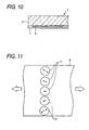
- a plastic sheet 9 is additionally subjected to an extension process during the manufacturing process, for ensuring strength and the accuracy of thickness. Consequently, the plastic sheet 9 possesses a thermal contraction characteristic (Bowing phenomenon), wherein a given directionality is imparted to the direction of heat contraction (see the directions indicated by the arrows provided in circles shown in Fig. 11).
- the plastic sheet 9 is applied integrally over the substrate 3 as a cover sheet 11 of the recording layer 5 as shown in Fig. 12, no problem arises when the optical disk is stored in an ordinary environment. However, when an optical disk is likely to be stored at high temperature and high humidity (e.g.
- JP-A-2002-92965 there has also already been proposed an optical disk, wherein an ultra-thin transparent cover layer is provided on a substrate with information signals formed therein, and wherein the transparent-cover-side of the substrate is exposed to a laser beam, to thereby record/reproduce the information signals.
- an optical disk substrate can usually be formed to a thickness of about 1.2 mm, the optical disk enables accurate transfer of irregularities even when the disk substrate is manufactured by means of an injection molding method.
- the laser beam used for recording/reproduction is radiated onto the side of the substrate covered with the ultra-thin transparent cover layer, and hence sufficient addressing of an increase in recording capacity has come to be feasible.
- the Blu-Ray disk requires a large-diameter anti-reflection characteristic, and hence a recording surface of the substrate is coated with a ultra-thin transparent cover layer, to thereby stabilize a characteristic of the disk and maintain the appearance of the disk when in use.
- the cover layer of the Blu-Ray disk has a thickness of about 0.1 mm.
- the disk After the disk has been coated with UV curing resin, the disk is usually subjected to hardening treatment.
- various Blu-Ray recording methods have already been proposed, users expect rewritability or the like.
- an organic-pigment-based recording material is frequently used.
- a UV laser beam is used for recording operation
- application of the UV-ray curing method to curing of a cover layer is less desirable as mentioned above.
- a thin-layer plastic sheet polycarbonate, TAC, PET, or the like
- an appropriate cover thickness is obtained.
- UV curing is not performed, and hence damage is less frequently inflicted on the organic-pigment-based recording material. Therefore, affixing of a thin-layer plastic sheet can be said to be an appropriate method.
- a plastic sheet In order to ensure strength and accuracy of thickness, a plastic sheet is inevitably subjected to a pull process during manufacturing processes. Consequently, the plastic sheet is imparted with an irreversible thermal expansion/shrinkage characteristic.
- the material When the material is integrally affixed to the disk substrate, no particular problem is encountered in preserving the disk in a normal environment. There may arise a case where the dimension of a cover layer is changed by thermal shrinkage or moisture shrinkage resulting from the disk being preserved at high temperature and high humidity, thereby imparting "warpage" to the substrate with the cover affixed thereto and inducing a change in the amount of tilt to exert an adverse influence on a recording/reproduction characteristic.
- a rigorous anti-reflection (AR) characteristic is set for the Blu-Ray disk [hence, the influence of the AR characteristic is greater than that on a CD or a DVD], and hence a nominal change in tilt induces deterioration of a characteristic.
- the invention has been conceived in view of the foregoing circumstances and aims at providing an optical disk capable of preventing warpage of a disk substrate having a cover sheet, and a method for affixing a display sheet to the optical disk, thereby stabilizing read/write characteristics of the optical disk and preventing deterioration of appearance of the optical disk.
- the present inventor has found that machining a plastic sheet into a circular shape and bonding the plastic sheet onto a side of the substrate as a image display layer, the side being opposite to a cover layer on the recording surface side of the substrate, in which the plastic sheet has the same characteristics as those of the cover layer, and thereby a balance between the image display layer and the cover layer can be achieved and that, as a result, a stable characteristic can be obtained even when the disk is preserved at high temperature and high humidity.
- the image display layer can be handled in the form of a sheet. After an image has been printed on the image display layer, the layer is affixed to a disk. Alternatively, after the image display layer has been affixed on a disk, an image is printed on the layer. Thus, an image can be printed on a disk by means of any of various techniques, thereby enabling enhancement of a commercial value.
- Figs. 14A and 14B are views for describing the structure of the Blu-Ray disk, wherein Fig. 14A is a plan view and Fig. 14B is a cross-sectional front view.
- the substrate 3 is polycarbonate having a thickness of 1.2 mm.
- the cover sheet 11 is made of PC (polycarbonate), TAC, or PET (polyethylene terephthalate).
- Another conceivable method is to affix a paper label on an optical disk and to enter contents of the optical disk on the label in characters, with a view toward easily ascertaining contents recorded on an optical disk. Ascertaining contents by reading characters is laborious and time-consuming and poses difficulty in using the disk for children or foreigners who do not understand characters.
- the optical disk of the invention no warpage arises in a disk even when the substrate is stored at high temperature, as a result of a sheet having the same physical characteristics as those of the cover sheet being affixed to the other side of the substrate.
- the sheet is made printable as a display sheet, and at least one or a required number of representative digital images showing recorded contents are printed, thereby enabling the user to ascertain contents of the optical disk at a glance.
- an image is printed on the sheet.
- the sheet is bonded to a disk substrate.
- a coincidence always arises between the optical disk and the recorded contents.
- an optical disk which is easily understandable for children or persons who cannot read characters.
- an optical disk comprising: a disk substrate having a recording layer formed on one surface of a substrate and a cover sheet applied over the recording layer; and a display sheet which has substantially the same physical characteristic as that of the cover sheet and is affixed to a surface of the disk substrate opposite to a surface thereof covered with the cover sheet.
- a display sheet having substantially the same physical characteristic as that of a cover sheet is affixed to a surface of a disk substrate opposite a surface thereof coated with the cover sheet, wherein the cover sheet is applied to a recording layer on one surface of a substrate .
- substantially the same physical characteristic is achieved on the front and back surfaces of the substrate.
- the forces exerted on the substrate from the sheet become equal to each other by virtue of the structural strength of the front and back of the substrate and a temperature change, thereby preventing occurrence of a warpage, which would otherwise tend to arise in the disk substrate.
- the read/write characteristics of the optical disk become stable, and good appearance of the optical disk is ensured simultaneously.
- an optical disk set forth in the first aspect of the invention, wherein the display sheet and the cover sheet substantially coincide with each other in terms of the direction of heat contraction and a heat contraction rate.
- the cover sheet and the display sheet are substantially identical with each other in terms of direction of heat contraction and a thermal contraction rate. Accordingly, even in the event of a large heat history, the cover sheet and the display sheet are identical with each other in the direction of heat contraction. Hence, the forces acting on the substrate cancel each other, thereby preventing warpage of the disk substrate.
- an optical disk as set forth in the first or second aspect of the invention, wherein the thickness of the display sheet falls within a range of 0.05 to 0.3 mm.
- the thickness of the display sheet can be made equal to that of the cover layer of an optical disk which enables mass-storage recording (by means of a so-called 0.1 mm cover layer system).
- forces caused by the cover layer can be canceled by each other on the opposite surface of the substrate.
- an optical disk comprising: a disk substrate having a recording layer formed on one surface of a substrate and a cover sheet applied over the recording layer; and a display sheet which has substantially the same physical characteristic as that of the cover sheet and an adhesive surface affixed to peeling paper and is an accessory separate from the disk substrate.
- a cover sheet having substantially the same physical characteristic as that of the cover sheet is provided as an accessory separate from the disk substrate, thereby enhancing the degree of freedom of the user in adopting an image formation method for use with a display sheet.
- an optical disk as set forth in any of the first to fourth aspects of the invention, wherein a mark indicating the direction of heat contraction of the cover sheet is provided on the cover sheet, and a mark indicating the direction of heat contraction of the display sheet is provided on the display sheet.
- the cover sheet provided with a mark is applied to a substrate beforehand, and the display sheet is affixed to the substrate in alignment with the mark of the cover sheet.
- the mark of the cover sheet is provided directly on the cover sheet. Hence, an error becomes unlikely to arise between the direction of heat contraction of the cover sheet and the mark.
- an optical disk as set forth in any of the first to fourth aspects of the invention, wherein a mark indicating the direction of heat contraction of the cover sheet is provided on the substrate, and a mark indicating the direction of heat contraction of the display sheet is provided on the display sheet.
- the cover sheet is applied to the substrate such that the mark provided on the substrate coincides with the direction of heat contraction.
- the display sheet is also affixed to the substrate while the mark provided on the substrate remains coincident with the mark. If the mark is provided on the surface of the substrate on which the display sheet is to be affixed, the necessity for viewing the mark of the cover sheet from the opposite surface through the substrate is obviated. The visibility achieved when the mark of the display sheet is aligned becomes better.
- an optical disk as set forth in any of the fifth to sixth aspects of the invention, wherein the mark corresponds to any one of a notch, a hole, and a slit section.
- the mark is formed from a notch, positioning of the mark can be performed with the aid of the sense of touch as well as with a visual check. Even when the mark is a hole, positioning of the mark can also be performed with the aid of the sense of touch as well as with a visual check, thereby enabling highly accurate positioning. If the mark is a slit section, highly accurate positioning becomes easy to achieve, and a loss is unlikely to arise in the display sheet. Hence, occurrence of a drop in the strength of the display sheet is prevented.
- an optical disk as set forth in the first aspect of the invention, wherein the display sheet is effectively formed from a two-layer structure; that is, upper and lower layers; the lower layer is a base layer including a fluorescent substance, and the upper layer is a image print layer provided on the base layer so as to cover the same.
- a base layer including a fluorescent color former is provided on the substrate, and the image print layer is provided thereon.
- a solar light beam having entered the fluorescent color former by way of a bright image portion of the image print layer causes the fluorescent color formation layer to illuminate, thereby radiating the image print layer from the back thereof.
- the image recorded on the image print layer assumes vibrant colors.
- an optical disk as set forth in the eighth aspect of the invention, wherein the base layer is formed on the substrate in an isotropically uniform manner; the image print layer is formed from a plurality of blocks; and a space between the blocks is taken as a non-print section.
- the solar light beam may fail to reach the fluorescent color former.
- the specially-provided fluorescent color former fails to exhibit the capability thereof.
- an optical disk as set forth in the eighth or ninth aspect of the invention, wherein one print image is formed from a plurality of blocks on the image print layer, and a space between the blocks is taken as a non-print section having transparency to light.
- one print image is formed from a plurality of blocks. Further, a non-print section which has light permeability and is not subjected to printing and an unprintable section on which nothing can be printed are provided on the image print layer. Hence, superior appearance of multi-window type is achieved. Since the solar light beam reaches the base layer by way of the transparent non-print section, the image can be seen in vivid colors.
- an optical disk as set forth in the eighth or ninth aspect of the invention, wherein different print images are formed into thumbnails in each block on the image print layer, and a space between said blocks is taken as a non-print section.
- a print image is formed in a thumbnail, thereby enabling easy and accurate ascertainment of contents.
- a solar light beam reaches a base layer by way of a transparent non-print section having light permeability. Hence, the image can be seen in vivid colors.
- an optical disk as set forth in any of ninth to eleventh aspects of the invention, wherein the non-print section is formed from a grid pattern, a radial pattern, a concentric pattern, or a combination thereof.
- the non-print section assumes a geometrical pattern, and hence superior appearance is achieved. Further, a solar light beam reaches the base layer by way of a transparent non-print section, and hence the image can be seen in vivid colors.
- a thin plastic sheet to be affixed on a disk substrate comprising: a printable area and an unprintable area are provided on the front or backs side of the sheet.
- a print section and a non-print section are automatically formed by means of only printing an image on the sheet, thereby offering convenience for the user.
- a method for affixing a display sheet to a disk substrate including: affixing a display sheet on a opposite surface of the disk substrate, which has a recording layer formed on a surface of a substrate and a cover sheet applied over the recording layer, the opposite surface being opposite to the surface of the disk substrate covered with the cover sheet, wherein a mark, which is provided on at least either the cover sheet or the substrate and indicates a direction of heat contraction of the cover sheet, is caused to coincide with a mark, which is provided on the display sheet and indicates a direction of heat contraction of the display sheet, thus affixing the display sheet on the opposite surface of the disk substrate.
- the method for affixing a display sheet to a disk substrate of the invention even a user who does not have any special equipment or technique can align the direction of heat contraction of the cover sheet with that of the display sheet by means of merely aligning the marks with each other.
- the forces acting on both the front and back of the substrate due to heat contraction can be easily canceled by each other.
- the display sheet Before being affixed to the substrate, the display sheet is a single sheet separate from the substrate.
- the optical disk of the invention enables application of various image formation methods for the display sheet, thus enhancing the degree of freedom of application of the image formation method to the display sheet.
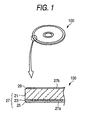
- Fig. 1 is a descriptive view showing the appearance of an optical disk according to a first embodiment of the invention and a fragmentary enlarged cross-sectional view of the optical disk.
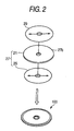
- Fig. 2 is a descriptive view showing an exploded perspective view and appearance of the optical disk shown in Fig. 1.
- Fig. 3 is a descriptive view showing an exploded perspective view and an external perspective view of the disk substrate provided with marks and a display sheet.
- Figs. 4A to 4C are descriptive views illustrating kinds of marks.
- Fig. 5 is a descriptive view representing processes for affixing a display sheet to the substrate.
- a recording layer 23 is formed on one side of a substrate 21.
- a cover sheet 25 is integrally provided on the recording layer 23, thus constituting a disk substrate 27.
- a display sheet 29 is affixed to a surface 27b of the disk substrate 27 opposite to a surface 27a on which the cover sheet 25 is integrally provided.
- the substrate 21 and the cover sheet 25 are transparent, and the display sheet 29 may be transparent or opaque.
- TAC having a high optical transmissivity is preferably used for the cover sheet 25 and the display sheet 29.
- a recording layer formed from an organic or inorganic material is preferably used for the recording layer 23.
- the cover sheet 25 and the display sheet 29 have substantially identical physical characteristics. Representative physical characteristics include the direction of heat contraction and a heat contraction rate. Specifically, in the optical disk 100 of the embodiment, the cover sheet 25 and the display sheet 29 are substantially identical with each other in terms of direction of heat contraction (i.e., the directions indicated by the arrows provided in the sheets shown in Fig. 2) and a thermal contraction rate. Accordingly, even in the event of a large heat history, the cover sheet 25 and the display sheet 29 are identical with each other in the direction of heat contraction. Hence, the forces acting on the substrate 21 cancel each other, thereby preventing warpage of the disk substrate 27.
- the thickness of the display sheet 29 is set within a range of 0.05 mm to 0.3 mm. As a result of the thickness of the display sheet 29 falling within the range, the thickness of the display sheet 29 can contribute to rendering uniform the thickness of the cover layer (i.e., the cover sheet 25 of the embodiment) of the optical disk for which a violet laser light source enabling mass-storage recording is to be used.
- the cover sheet 25 possesses a superior light transmissivity with respect to the wavelength of recording/playback light. The force stemming from the display sheet can be canceled by the opposite surface of the substrate 21.
- the cover sheet 25 is affixed to the substrate 21 when production of the optical disk 100 is finished.
- the display sheet 29 may be provided separately from the disk substrate 27.
- the optical disk 100 may also be configured by comprising the disk substrate 27 having the recording layer 23 formed on one surface of the substrate 21 and the cover sheet 25 applied over the recording layer 23; and the display sheet 29 which has substantially the same physical characteristic as that of the cover sheet 25 and an adhesive surface affixed to unillustrated peeling paper and is available as an accessory separate from the disk substrate 27.
- the display sheet 29 is affixed to the disk substrate 27 by the user. Therefore, a mark M1 indicating the direction of heat contraction of the cover sheet 25 is provided on the cover sheet 25, and a mark M2 indicating the direction of heat contraction of the display sheet 29 is provided on the display sheet 29.
- the mark M1 of the cover sheet 25 becomes visible from the opposite surface 27b of the disk substrate 27 as a result of the cover sheet 25 being affixed to the transparent substrate 21.
- the display sheet 29 is affixed to the disk substrate 27 while being aligned with the mark M1.
- the degree of freedom of an image formation method to be applied to the display sheet 29 of the user is enhanced. Specifically, an image formation method, such as insertion of only the display sheet 29 into a printer, becomes available.
- the cover sheet 25 provided with the mark M1 is applied over the substrate 21 beforehand, and the display sheet 29 is affixed to the substrate 21 in alignment with the mark M1 of the cover sheet 25.
- the cover sheet 25 coincides with the display sheet 29 in the direction of heat contraction.
- the mark M1 of the cover sheet 25 is provided directly on the cover sheet 25, and hence an error becomes unlikely to arise between the direction of heat contraction of the cover sheet 25 and the mark M1.
- the mark may be provided on the substrate 21.
- the cover sheet 25 is applied to the substrate 21 such that the mark (not shown) provided on the substrate 21 coincides with the direction of heat contraction.
- the display sheet 29 is also affixed to the substrate 21 while the mark provided on the substrate 21 remains coincident with the mark M2. If the mark is provided on the surface of the substrate 21 on which the display sheet 29 is to be affixed, the necessity for viewing the mark M1 of the cover sheet 25 from the opposite surface 27b through the substrate 21 is obviated. The visibility achieved when the mark of the display sheet 29 is aligned becomes better.
- the marks M1, M2 can be embodied as any one of a notch 31, a hole 33, a slit section 35, and a dot (a print formed in a black dot pattern) omitted from the drawings, or as a combination thereof.
- the mark M2 is formed from the notch 31, positioning of the mark M2 can be performed with the aid of the sense of touch as well as with a visual check.
- positioning of the mark M2 can also be performed with the aid of the sense of touch as well as with a visual check, thereby enabling highly accurate positioning.
- the mark M2 is the slit section 35, highly-accurate positioning becomes easy to achieve, and a loss does not arise in the display sheet 29. Hence, occurrence of a drop in the strength of the display sheet 29 is prevented.
- the substrate 21 is not provided with any marks, and the cover sheet 25 is provided with a dot-shaped mark M3.
- the mark M3 is provided on a line extending in the direction of a diameter, the line indicating the direction of heat contraction of the cover sheet 25. Consequently, the disk substrate 27 to which the cover sheet 25 is applied enables viewing of the mark M3 from the opposite surface 27b.
- the mark M2 formed from the notch 31 cut toward the inside with reference to the radial direction is provided in the outer periphery of the display sheet 29.
- the mark M2 is also provided on the line extending in the direction of the diameter, the line indicating the direction of heat contraction of the display sheet 29.
- the cover sheet 25 is applied to the substrate 21 beforehand, thereby constituting the disk substrate 27.
- the display sheet 29 When the display sheet 29 is affixed to the disk substrate 27, the mark M3 of the cover sheet 25 adhering to the substrate 21 is viewed from the opposite surface 27b of the disk substrate 27.
- the display sheet 29 is affixed to the opposite surface 27b of the disk substrate 27 while the mark M2 of the display sheet 29 fits into the notch 31.
- the optical disk 100 wherein the cover sheet 25 and the display sheet 29, being provided on the respective surfaces of the disk substrate 27, are aligned with each other in terms of direction of heat contraction.
- the display sheet 29 having substantially the same physical characteristic as that of the cover sheet 25 is affixed to the surface 27b of the disk substrate 27 opposite to a surface thereof coated with the cover sheet 25, wherein the cover sheet 25 is applied on the recording layer 23 provided on one surface of the substrate 27.
- substantially the same physical characteristic is achieved on the front and back surfaces of the substrate 27.
- the forces exerted on the substrate 21 from the sheets become equal to each other by virtue of the structural strength of the front and back of the substrate and a temperature change, thereby preventing occurrence of a warpage, which would otherwise tend to arise in the disk substrate 27.
- the read/write characteristics of the optical disk 100 become stable, and good appearance of the optical disk 100 is ensured simultaneously.
- the display sheet 29 is a single sheet separate from the substrate 21.
- the optical disk of the invention enables application of various image formation methods for the display sheet 29, thus enhancing the degree of freedom of application of the image formation method to the display sheet 29.
- Fig. 6 is an exploded perspective view of an optical disk according to a second embodiment of the invention.
- a recording layer 23 is formed on a substrate 21, and a cover sheet 25 is integrally provided on the recording layer 23, thus constituting a disk substrate 27.
- the display sheet 39 is bonded to a surface 27b of the disk substrate 27, the surface 27b being opposite to a surface of the disk substrate 27 on which the cover sheet 25 is integrally provided.
- the present embodiment is characterized by formation of the display sheet 39 from an image print layer 40 and a fluorescent base layer 41.
- the display sheet 39 is formed from a material having substantially the same physical characteristic as that of the cover sheet 25. Therefore, the display sheet 39 is formed from polycarbonate, TAC, or polyethylene terephthalate.
- the fluorescent color former of the fluorescent base layer 41 can be embodied by paint containing zinc oxide or paint containing phosphor.
- Fig. 8A is a longitudinal cross-sectional view of the optical disk shown in Fig. 6.
- reference numeral 39 designates a display sheet formed from an image print layer 40 and a fluorescent base layer 41.
- Reference numeral 21 designates a substrate, and 25 designates a cover sheet.
- solar light beams L1, L2 have arrived at the image print layer 40, the light beams are reflected from an image portion of the image print layer 40, thereby arriving at the viewer's eyes.
- a portion of the solar light beam L2 transmits through an unprinted portion of the image and a printed portion having a bright, pale color close to transparence, both of which are on the image print layer 40, to thereby arrive at the fluorescent base layer 41.
- UV rays of the solar light beam L2 excite a fluorescent color former, causing it to illuminate. Color-forming light radiates the image portion from its back. The user can see the image in vivid colors by means of a backlight effect.
- the solar light beam having entered the fluorescent color former from a bright portion of the image on the display sheet illuminates, thereby radiating the display sheet from the back thereof. Therefore, the image recorded on the display sheet assumes a bright color.
- Fig. 7 is an exploded perspective view of an optical disk according to a third embodiment of the invention.
- the third embodiment is characterized in that the image print layer 40 of the display sheet 39 is divided into a print section 40a and a non-print section 40b.
- the non-print section 40b may be a section (i.e., a non-print section) which is not actively subjected to printing during printing operation, or a section (i.e., an unprintable section) on which nothing can be printed during printing operation.
- the section is coated with a hydrophilic substance.
- Fig. 8B shows a longitudinal cross-sectional view of the optical disk shown in Fig. 7.
- reference numeral 39 designates a display sheet and in that the display sheet 39 is formed from the image print layer 40 and the fluorescent base layer 41.
- Reference numeral 21 designates a substrate; and 25 designates a cover sheet.
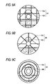
- Figs. 9A to 9C show various patterns assumed by the non-print section 40b of the image print layer 40 provided on the display sheet 39 according to a fourth embodiment of the invention.
- Reference numeral 40 designates an image print layer; 40a designates a printable section; and 40b designates a non-print section.
- the non-print section 40b assumes a grid pattern.
- the non-print section 40b assumes a radial pattern.
- the non-print section 40b assumes a concentric pattern.
- the print section 40a corresponding to the image becomes vibrant, and also the entire image provides an impression of a multi-pane window or jigsaw, thereby improving an aesthetic value.
- widths and number of lattices, radial lines, and concentric circles may be changed by design, as required.
- any of the non-print sections shown in Figs. 9A to 9C may be used solely. However, as a matter of course, they may also be used in combination.
- the present invention is not limited to this disk. Needless to say, if the present invention is applied to another recording disk (CD, DVD) in the same manner, an image printed on a thin plastic sheet can be viewed in vivid colors.
- a display sheet having substantially the same physical characteristic as that of a cover sheet is affixed to a surface of a disk substrate opposite a surface thereof coated with a cover sheet, wherein the cover sheet is applied to a recording layer on one surface of a substrate.
- the optical disk of the invention enables application of various image formation methods for the display sheet, thus enhancing the degree of freedom of application of the image formation method to the display sheet and improving the commercial value of the optical disk.
- the optical disk according to the invention is suitable for an information recording disk for recording a large volume of information (including image and music information) such as a Blu-Ray disk which records data through use of UV rays of short wavelength and requires a large-diameter anti-reflection characteristic.
- the display sheet can be constituted such that the image print layer is placed on a fluorescent color formation layer. Hence, illumination of the fluorescent color formation layer improves identification of an upper print surface, thereby improving appearance.
- a light beam which excites fluorescence can readily reach a base fluorescent layer, thereby ensuring ease of identification of the image print layer (i.e., appearance).
- the image print layer is constituted of a plurality of blocks of several shapes. Hence, diversification of a design of a single-piece image or display of a thumbnail can be readily effected while appearance is ensured.
Landscapes
- Engineering & Computer Science (AREA)
- Manufacturing & Machinery (AREA)
- Optical Record Carriers And Manufacture Thereof (AREA)
Abstract
Description
Claims (14)
- An optical disk comprising:a disk substrate having a recording layer formed on one surface of a substrate and a cover sheet applied over the recording layer; anda display sheet which has substantially the same physical characteristic as that of the cover sheet and is affixed to a surface of the disk substrate opposite to a surface thereof covered with the cover sheet.
- The optical disk according to claim 1, wherein the display sheet and the cover sheet substantially coincide with each other in terms of the direction of heat contraction and a heat contraction rate.
- The optical disk according to claim 1, wherein the thickness of the display sheet falls within a range of 0.05 to 0.3 mm.
- An optical disk comprising:a disk substrate having a recording layer formed on one surface of a substrate and a cover sheet applied over the recording layer; anda display sheet which has substantially the same physical characteristic as that of the cover sheet and an adhesive surface affixed to peeling paper and is an accessory separate from the disk substrate.
- The optical disk according to claim 1 or claim 4, wherein a mark indicating the direction of heat contraction of the cover sheet is provided on the cover sheet, and a mark indicating the direction of heat contraction of the display sheet is provided on the display sheet.
- The optical disk according to claim 1 or claim 4, wherein a mark indicating the direction of heat contraction of the cover sheet is provided on the substrate, and a mark indicating the direction of heat contraction of the display sheet is provided on the display sheet.
- The optical disk according to claim 5 or claim 6, wherein the mark corresponds to any one of a notch, a hole, and a slit section.
- The optical disk according to claim 1, wherein the display sheet is effectively formed from a two-layer structure; that is, upper and lower layers, wherein the lower layer is a base layer including a fluorescent substance, and the upper layer is an image print layer provided on the base layer so as to cover the same.
- The optical disk according to claim 8, wherein the base layer is formed on the substrate in an isotropically uniform manner; the image print layer is formed from a plurality of blocks; and a space between the blocks is taken as a non-print section.
- The optical disk according to claim 8, wherein one print image is formed from a plurality of blocks on the image print layer, and a space between the blocks is taken as a non-print section having transparency to light.
- The optical disk according to claim 8, wherein different print images are formed into thumbnails in each block on the image print layer, and a space between said blocks is taken as a non-print section.
- The optical disk according to claim 9, wherein the non-print section is formed from a grid pattern, a radial pattern, a concentric pattern, or a combination thereof.
- A thin plastic sheet to be affixed on a disk substrate, comprising:a printable area and an unprintable area provided on the front or back side of the sheet.
- A method for affixing a display sheet to a disk substrate, the method including:wherein a mark, which is provided on at least either the cover sheet or the substrate and indicates a direction of heat contraction of the cover sheet, is caused to coincide with a mark, which is provided on the display sheet and indicates a direction of heat contraction of the display sheet, thus affixing the display sheet on the opposite surface of the disk substrate.affixing a display sheet on an opposite surface of the disk substrate, which has a recording layer formed on a surface of a substrate and a cover sheet applied over the recording layer, the opposite surface being opposite to the surface of the disk substrate covered with the cover sheet,
Applications Claiming Priority (4)
| Application Number | Priority Date | Filing Date | Title |
|---|---|---|---|
| JP2003014839 | 2003-01-23 | ||
| JP2003014839A JP2004227684A (en) | 2003-01-23 | 2003-01-23 | Optical disc and method of attaching display sheet to optical disc |
| JP2003016393A JP2004227716A (en) | 2003-01-24 | 2003-01-24 | Recording disk |
| JP2003016393 | 2003-01-24 |
Publications (3)
| Publication Number | Publication Date |
|---|---|
| EP1443507A2 true EP1443507A2 (en) | 2004-08-04 |
| EP1443507A3 EP1443507A3 (en) | 2007-04-04 |
| EP1443507B1 EP1443507B1 (en) | 2009-03-25 |
Family
ID=32658587
Family Applications (1)
| Application Number | Title | Priority Date | Filing Date |
|---|---|---|---|
| EP04250317A Expired - Lifetime EP1443507B1 (en) | 2003-01-23 | 2004-01-21 | Optical disk with display sheet and method for affixing |
Country Status (3)
| Country | Link |
|---|---|
| US (1) | US7359309B2 (en) |
| EP (1) | EP1443507B1 (en) |
| DE (1) | DE602004020133D1 (en) |
Families Citing this family (11)
| Publication number | Priority date | Publication date | Assignee | Title |
|---|---|---|---|---|
| US7418726B2 (en) * | 2003-01-02 | 2008-08-26 | Intellectual Property & Ideas, Llc | Illuminated devices using UV-LED's |
| TWI253646B (en) * | 2004-12-03 | 2006-04-21 | Daxon Technology Inc | Luminant optical media |
| JP2006260728A (en) * | 2005-03-18 | 2006-09-28 | Fuji Photo Film Co Ltd | Optical disk |
| US8675464B2 (en) | 2005-11-03 | 2014-03-18 | Cinram Group, Inc. | Dual sided optical storage media and method for making same |
| US7684309B2 (en) * | 2005-11-03 | 2010-03-23 | Cinram International Inc. | Multi-purpose high-density optical disc |
| US7986611B1 (en) | 2007-03-22 | 2011-07-26 | Cinram International Inc. | High-density optical recording media and method for making same |
| US7910191B1 (en) | 2006-03-09 | 2011-03-22 | Cinram International Inc. | Method for forming light-transmitting cover layer for optical recording medium |
| US20110096655A1 (en) * | 2006-03-09 | 2011-04-28 | Cinram International Inc. | Forming light-transmitting cover layer for recording medium |
| US8739299B1 (en) | 2009-12-24 | 2014-05-27 | Cinram Group, Inc. | Content unlocking |
| US8850981B2 (en) | 2011-02-23 | 2014-10-07 | Sony Dadc Us Inc. | Single-sided printing providing dual-sided reading of print on optical discs |
| US20150279320A1 (en) * | 2014-03-26 | 2015-10-01 | Nike, Inc. | Subtractive Color Change System and Method |
Family Cites Families (13)
| Publication number | Priority date | Publication date | Assignee | Title |
|---|---|---|---|---|
| JPH0397135A (en) | 1989-09-08 | 1991-04-23 | Sharp Corp | Optical memory element and sheet for optical memory element |
| JPH04195745A (en) * | 1990-09-13 | 1992-07-15 | Mitsubishi Electric Corp | Optical disk |
| US5900098A (en) * | 1996-10-11 | 1999-05-04 | Wea Manufacturing Inc. | Methods for bonding structurally dissimilar optical discs |
| JPH1125508A (en) * | 1997-06-30 | 1999-01-29 | Toshiba Emi Ltd | Optical disk with small diameter recording area |
| US6735166B1 (en) * | 1997-07-09 | 2004-05-11 | Sanyo Electric Co., Ltd. | Optical disk with pattern and fabrication method thereof |
| JPH11238255A (en) * | 1998-02-21 | 1999-08-31 | Taiyo Yuden Co Ltd | Optical disk |
| EP1031972B1 (en) * | 1999-02-24 | 2004-12-22 | Sharp Kabushiki Kaisha | Optical information recording medium |
| JP2000322767A (en) | 1999-05-10 | 2000-11-24 | Victor Co Of Japan Ltd | Optical disk |
| JP2002092965A (en) | 2000-09-13 | 2002-03-29 | Sony Corp | Optical recording medium and manufacturing method thereof |
| TW565835B (en) * | 2001-01-10 | 2003-12-11 | Ricoh Kk | Phase change optical recording medium |
| JP3431612B2 (en) * | 2001-06-04 | 2003-07-28 | 株式会社東芝 | Optical disc, optical disc apparatus suitable for the optical disc, and information recording / reproducing method |
| JP3656591B2 (en) * | 2001-06-28 | 2005-06-08 | ソニー株式会社 | Method of manufacturing stamper for manufacturing optical recording medium and method of manufacturing optical recording medium |
| JP3876836B2 (en) * | 2003-01-14 | 2007-02-07 | ソニー株式会社 | Information recording medium and label for information recording medium |
-
2004
- 2004-01-21 DE DE602004020133T patent/DE602004020133D1/en not_active Expired - Lifetime
- 2004-01-21 US US10/760,377 patent/US7359309B2/en not_active Expired - Fee Related
- 2004-01-21 EP EP04250317A patent/EP1443507B1/en not_active Expired - Lifetime
Also Published As
| Publication number | Publication date |
|---|---|
| US20040184390A1 (en) | 2004-09-23 |
| EP1443507B1 (en) | 2009-03-25 |
| DE602004020133D1 (en) | 2009-05-07 |
| US7359309B2 (en) | 2008-04-15 |
| EP1443507A3 (en) | 2007-04-04 |
Similar Documents
| Publication | Publication Date | Title |
|---|---|---|
| US4903255A (en) | Optical recording disc | |
| US7359309B2 (en) | Optical disk, thin plastic sheet, and method for affixing display sheet to disk substrate | |
| JPH08273201A (en) | optical disk | |
| US20060204894A1 (en) | Optical recording medium and displaying method on surface of the medium | |
| US20050270963A1 (en) | Optical recording medium | |
| EP0458968B1 (en) | Sealed-type optical card | |
| US20060132576A1 (en) | Optical media with laminated inkjet receptor | |
| JP2754215B2 (en) | Information recording medium | |
| JP2004227716A (en) | Recording disk | |
| JP2002092952A (en) | Optical disk | |
| JP2513267B2 (en) | Optical recording medium | |
| JP2004227684A (en) | Optical disc and method of attaching display sheet to optical disc | |
| JP2000040264A (en) | Draw type optical disk and printer capable of partial printing | |
| CA2390064C (en) | Rewritable compact disk having determining function for record data | |
| JP3030455B2 (en) | Optical disc manufacturing method | |
| JP3490846B2 (en) | Double-sided recording disk | |
| JP2000251331A (en) | Information recording medium, index printer and index information display method | |
| JPH08297867A (en) | Optical disc media | |
| US20070285489A1 (en) | Label device for optical disc | |
| US20070187504A1 (en) | Optical disc | |
| JPH0340239A (en) | Optical recording medium | |
| TW514906B (en) | Optical information recording media | |
| US20070127332A1 (en) | Optical recording media | |
| CN101488355B (en) | System and method for optical media marking | |
| JP2006031791A (en) | Optical recording medium |
Legal Events
| Date | Code | Title | Description |
|---|---|---|---|
| PUAI | Public reference made under article 153(3) epc to a published international application that has entered the european phase |
Free format text: ORIGINAL CODE: 0009012 |
|
| AK | Designated contracting states |
Kind code of ref document: A2 Designated state(s): AT BE BG CH CY CZ DE DK EE ES FI FR GB GR HU IE IT LI LU MC NL PT RO SE SI SK TR |
|
| AX | Request for extension of the european patent |
Extension state: AL HR LT LV MK |
|
| PUAL | Search report despatched |
Free format text: ORIGINAL CODE: 0009013 |
|
| RAP1 | Party data changed (applicant data changed or rights of an application transferred) |
Owner name: FUJIFILM CORPORATION |
|
| AK | Designated contracting states |
Kind code of ref document: A3 Designated state(s): AT BE BG CH CY CZ DE DK EE ES FI FR GB GR HU IE IT LI LU MC NL PT RO SE SI SK TR |
|
| AX | Request for extension of the european patent |
Extension state: AL LT LV MK |
|
| 17P | Request for examination filed |
Effective date: 20070913 |
|
| AKX | Designation fees paid |
Designated state(s): DE FR GB |
|
| 17Q | First examination report despatched |
Effective date: 20071123 |
|
| GRAP | Despatch of communication of intention to grant a patent |
Free format text: ORIGINAL CODE: EPIDOSNIGR1 |
|
| GRAS | Grant fee paid |
Free format text: ORIGINAL CODE: EPIDOSNIGR3 |
|
| GRAA | (expected) grant |
Free format text: ORIGINAL CODE: 0009210 |
|
| AK | Designated contracting states |
Kind code of ref document: B1 Designated state(s): DE FR GB |
|
| REG | Reference to a national code |
Ref country code: GB Ref legal event code: FG4D |
|
| REF | Corresponds to: |
Ref document number: 602004020133 Country of ref document: DE Date of ref document: 20090507 Kind code of ref document: P |
|
| PLBE | No opposition filed within time limit |
Free format text: ORIGINAL CODE: 0009261 |
|
| STAA | Information on the status of an ep patent application or granted ep patent |
Free format text: STATUS: NO OPPOSITION FILED WITHIN TIME LIMIT |
|
| 26N | No opposition filed |
Effective date: 20091229 |
|
| PGFP | Annual fee paid to national office [announced via postgrant information from national office to epo] |
Ref country code: FR Payment date: 20100208 Year of fee payment: 7 |
|
| PGFP | Annual fee paid to national office [announced via postgrant information from national office to epo] |
Ref country code: GB Payment date: 20100120 Year of fee payment: 7 Ref country code: DE Payment date: 20091224 Year of fee payment: 7 |
|
| GBPC | Gb: european patent ceased through non-payment of renewal fee |
Effective date: 20110121 |
|
| REG | Reference to a national code |
Ref country code: FR Ref legal event code: ST Effective date: 20110930 |
|
| PG25 | Lapsed in a contracting state [announced via postgrant information from national office to epo] |
Ref country code: FR Free format text: LAPSE BECAUSE OF NON-PAYMENT OF DUE FEES Effective date: 20110131 |
|
| PG25 | Lapsed in a contracting state [announced via postgrant information from national office to epo] |
Ref country code: GB Free format text: LAPSE BECAUSE OF NON-PAYMENT OF DUE FEES Effective date: 20110121 |
|
| REG | Reference to a national code |
Ref country code: DE Ref legal event code: R119 Ref document number: 602004020133 Country of ref document: DE Effective date: 20110802 |
|
| PG25 | Lapsed in a contracting state [announced via postgrant information from national office to epo] |
Ref country code: DE Free format text: LAPSE BECAUSE OF NON-PAYMENT OF DUE FEES Effective date: 20110802 |