EP1443454A2 - Magnetic detection device - Google Patents
Magnetic detection device Download PDFInfo
- Publication number
- EP1443454A2 EP1443454A2 EP03258078A EP03258078A EP1443454A2 EP 1443454 A2 EP1443454 A2 EP 1443454A2 EP 03258078 A EP03258078 A EP 03258078A EP 03258078 A EP03258078 A EP 03258078A EP 1443454 A2 EP1443454 A2 EP 1443454A2
- Authority
- EP
- European Patent Office
- Prior art keywords
- magnetic
- gap
- roller unit
- unit
- detection device
- Prior art date
- Legal status (The legal status is an assumption and is not a legal conclusion. Google has not performed a legal analysis and makes no representation as to the accuracy of the status listed.)
- Granted
Links
Images


Classifications
-
- G—PHYSICS
- G06—COMPUTING OR CALCULATING; COUNTING
- G06K—GRAPHICAL DATA READING; PRESENTATION OF DATA; RECORD CARRIERS; HANDLING RECORD CARRIERS
- G06K7/00—Methods or arrangements for sensing record carriers, e.g. for reading patterns
- G06K7/08—Methods or arrangements for sensing record carriers, e.g. for reading patterns by means detecting the change of an electrostatic or magnetic field, e.g. by detecting change of capacitance between electrodes
- G06K7/082—Methods or arrangements for sensing record carriers, e.g. for reading patterns by means detecting the change of an electrostatic or magnetic field, e.g. by detecting change of capacitance between electrodes using inductive or magnetic sensors
- G06K7/083—Methods or arrangements for sensing record carriers, e.g. for reading patterns by means detecting the change of an electrostatic or magnetic field, e.g. by detecting change of capacitance between electrodes using inductive or magnetic sensors inductive
- G06K7/084—Methods or arrangements for sensing record carriers, e.g. for reading patterns by means detecting the change of an electrostatic or magnetic field, e.g. by detecting change of capacitance between electrodes using inductive or magnetic sensors inductive sensing magnetic material by relative movement detecting flux changes without altering its magnetised state
-
- G—PHYSICS
- G06—COMPUTING OR CALCULATING; COUNTING
- G06K—GRAPHICAL DATA READING; PRESENTATION OF DATA; RECORD CARRIERS; HANDLING RECORD CARRIERS
- G06K13/00—Conveying record carriers from one station to another, e.g. from stack to punching mechanism
- G06K13/02—Conveying record carriers from one station to another, e.g. from stack to punching mechanism the record carrier having longitudinal dimension comparable with transverse dimension, e.g. punched card
- G06K13/04—Details, e.g. flaps in card-sorting apparatus
- G06K13/05—Capstans; Pinch rollers
-
- G—PHYSICS
- G06—COMPUTING OR CALCULATING; COUNTING
- G06K—GRAPHICAL DATA READING; PRESENTATION OF DATA; RECORD CARRIERS; HANDLING RECORD CARRIERS
- G06K13/00—Conveying record carriers from one station to another, e.g. from stack to punching mechanism
- G06K13/02—Conveying record carriers from one station to another, e.g. from stack to punching mechanism the record carrier having longitudinal dimension comparable with transverse dimension, e.g. punched card
- G06K13/06—Guiding cards; Checking correct operation of card-conveying mechanisms
-
- G—PHYSICS
- G07—CHECKING-DEVICES
- G07D—HANDLING OF COINS OR VALUABLE PAPERS, e.g. TESTING, SORTING BY DENOMINATIONS, COUNTING, DISPENSING, CHANGING OR DEPOSITING
- G07D11/00—Devices accepting coins; Devices accepting, dispensing, sorting or counting valuable papers
- G07D11/40—Device architecture, e.g. modular construction
-
- G—PHYSICS
- G07—CHECKING-DEVICES
- G07D—HANDLING OF COINS OR VALUABLE PAPERS, e.g. TESTING, SORTING BY DENOMINATIONS, COUNTING, DISPENSING, CHANGING OR DEPOSITING
- G07D7/00—Testing specially adapted to determine the identity or genuineness of valuable papers or for segregating those which are unacceptable, e.g. banknotes that are alien to a currency
- G07D7/04—Testing magnetic properties of the materials thereof, e.g. by detection of magnetic imprint
Definitions
- This invention relates to a magnetic detection device for detecting magnetic ink printed on media, the device being applicable to, for instance, a valuable media processing machine to inspect the media as securities.
- This kind of magnetic detection device is equipped with a magnetic sensor and a conveying roller mechanism that are arranged opposing to each other with a gap between. Media are passed through the magnetic sensor and the conveying roller mechanism and printed magnetic inks are detected.
- media are needed to pass through the magnetic detection device in contact with the surface of the magnetic sensor and conveyed while kept pushed against the surface of the magnetic sensor by conveying rollers.
- the magnetic sensor is statically installed and the conveying rollers are installed rotatably.
- the magnetic sensor and the conveying rollers are arranged with a certain gap between them so that they do not contact each other.
- a gap between the surface of the magnetic sensor and the surfaces of the conveying rollers is adjusted by moving the conveying roller mechanism close to or far away from the surface of the magnetic sensor.
- a magnetic detection device comprises a magnetic head that detects magnetic information recorded on media that are conveyed; conveying rollers arranged with a prescribed gap against the magnetic head; a roller unit to which the conveying rollers are attached; a fixing unit that installs the roller unit movably in the direction to contact to or leave away from the magnetic head; and eccentric shafts that are provided rotatably between the fixing unit and the roller unit, wherein the roller unit is moved relatively to the fixing unit by rotating the eccentric shafts and the gap between the magnetic head and the conveying rollers is thus adjusted.
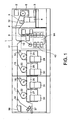
- FIG. 1 shows a valuable media processing machine for inspecting, classifying and processing such media as valuable securities (hereinafter referred to as securities) according to the result of inspection.
- a display panel 2 and an operating panel 3 On one side of the main body of the valuable media processing machine, there are a display panel 2 and an operating panel 3 provided. There is provided a supply portion 4 into which securities are put near operating panel 3. Securities put into supply portion 4 are taken out one by one by a take-out roller. There is a reject pocket 6 provided below display panel 2 for stacking securities that are to be discharged.
- Securities taken out by take-out roller 5 are conveyed to an inspection unit 9 through a first conveying path 8.
- Various kinds of sensor units 9 that are selectively used are provided in inspection unit 9.
- a second conveying path 11 and a reject sheet conveying path 12 are connected through a first gate 10.
- a first to fourth stackers 19 to 22 are connected through second to fifth gates 14 to 17.
- First to fourth stackers 19 to 22 are provided with banding units 24 to 27, respectively.
- containers 29 to 32 for containing banded securities are provided in front of banding units 24 to 27.
- an inspection stacker 36 and a shredder 37 are connected through a sixth gate 34.
- Securities put into supply portion 4 are taken out one by one by the rotation of take-out roller 5.
- the taken out securities are conveyed to sensor unit 9 and when passing through sensor unit 9, magnetic information of the securities is inspected.
- the inspected securities are sorted for sending to second conveying path 11 or reject sheet conveying path 12 by the movement of first gate 10 based on the inspection result.
- Securities sorted for reject sheet conveying path 12 are stacked in reject packet 6.
- Securities sorted for second conveying path 11 are sent to first to fourth stackers 19 to 22 or inspection stacker 36 or shedder 37 by the movement of second to sixth gates 14 to 17 and 34.
- securities sent to first to fourth stackers are accumulated to specify number sheets, for instance, 100 sheets, they are banded by banding units 24 to 27 and contained in containers 29 to 32.
- Magnetic detection unit 40 that is one of magnetic detection devices of various kinds of sensor units 9A. This magnetic detection unit 40 is to detect magnetic ink printed on securities. What are printed in magnetic ink on securities are, for instance, serial numbers.
- FIG. 2 is a perspective view showing magnetic detection unit 40
- FIG. 3 is its plan view
- FIG. 4 is its front view.
- Magnetic detection unit 40 is composed of a magnetic head 41 as a detection means and a conveying roller mechanism 42, which are placed opposing to each other through a medium conveying path (with a gap).
- the rear sides of magnetic head 41 and conveying roller mechanism 42 are fixed to a support frame 44.
- Conveying roller mechanism 42 is composed of a fixing unit 45 and a roller unit 47 that is movably provided on the lower surface side of fixing unit 45. Roller unit 47 is movable in the direction to contact to or leave away from magnetic head 41 and fixed to fixing unit 45 with a fixing member 46.
- Upper and lower conveying rollers 48a and 48b are installed to roller unit 47. Upper and lower conveying units 48a and 48b are arranged opposing to magnetic head 41. Plural upper and lower conveying rollers 48a and 48b are installed to a rotating shaft in its axial direction and arranged in the state partially nested each other.
- bracket 50 On the upper surface of roller unit 47, a bracket 50 is statically provided. A first upright portion 50a is formed at one end side of bracket 50 and a second upright portion 50b is formed at the other end side integrally.
- a first eccentric shaft 51 is installed as an adjusting means.
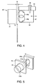
- the front end of first eccentric shaft 51 is inserted into a long hole 50c formed in the vertical direction on first upright portion 50a of bracket 50 as illustrated in a diagram shown in FIG. 5.
- a second eccentric shaft 52 is installed as an adjusting means to second upright portion 50b of bracket 50.
- the front end of second eccentric shaft 52 is inserted into a long hole (not illustrated) formed in the vertical direction on fixing unit 45.
- groove portions 51b and 52b are formed into which a slot-head screwdriver can fit.
- First and second eccentric shafts 51 and 52 are arranged out of alignment from the same line so that they are not collinear positioned.
- a medium G (shown in FIG. 4) is sent between magnetic head 41 and conveying rollers 48a and 48b of thus composed magnetic detection unit 40 and magnetic ink is detected by magnetic head 41.
- the medium K is pressed against magnetic head 41 by conveying rollers 48a and 48b.
- a gap between magnetic head 41 and conveying rollers 48a and 48b must be maintained properly.
- first eccentric shaft 51 rotates first eccentric shaft 51 by inserting the tip of a slot-head screwdriver into groove portion 51b of a head portion 51a of first eccentric shaft 51.
- the front end of first eccentric shaft 51 is rotated in long hole 50c of first upright portion 50a of bracket 50.
- upright portion 50a is moved in the arrow direction and moves roller unit 47 in the arrow direction.
- the front side gap between magnetic sensor 41 and conveying rollers 48a and 48b is adjusted as a result of this movement.
- the gap between magnetic sensor 41 and conveying rollers 48a and 48b is adjusted as a result of the rotation of eccentric shafts 51 and 52.
- eccentric shafts 51 and 52 it is possible to make a gap small or large by the same operation. Furthermore, the adjustment can be made easily using such a general tool as a screwdriver.
- first and second eccentric shafts 51 and 52 it becomes easy to adjust balance of gaps at several points. This is because the position of roller unit 57 is kept unchanged unless eccentric shafts 51 and 52 themselves rotate and it is possible to adjust a gap at one point independently by keeping a gap at another point. Thus, in such a case wherein a wide detection area of magnetic detection as in this embodiment is demanded, it is possible to realize it by easily adjusting a prescribed gap over the entire area.
- first and second eccentric shafts 51 and 52 are arranged out of alignment each other by displacing from the same line, when second eccentric shaft is rotated with a screwdriver, it is possible to rotate second eccentric shaft smoothly unobstructed by first eccentric shaft 51.
- FIG. 6 shows a magnetic detection unit that is capable of adjusting gap G between magnetic head 41 and conveying rollers 48a and 48b as another aspect of this invention.
- An arm member 57 is installed to support frame 44 in the oscillatory state. That is, arm member 57 is attached to support frame 44 via a rotating shaft 53 so that its almost central portion in the longitudinal direction becomes the center of rotation. There is a long hole 54 formed at the left to arm member 57 shown in FIG. 6 and arm member 57 is fixed to support frame 44 by fastening a screw 55 inserted into this long hole 54. When screw 55 is loosened, arm member 57 can be oscillated in the arrow direction along long hold 54.
- eccentric cam 56 At the right side of arm member 57 shown in FIG. 6, there is an eccentric cam 56 attached to support frame 44 through a rotating shaft 56a.
- Eccentric cam 56 has a groove portion 56b formed on its surface so that a minus screwdriver can be inserted into it.
- eccentric cam 56 rotates eccentrically between the solid line position and the dotted line position shown in the figure.
- arm member 57 oscillates in the arrow direction.
- Roller unit 47 is installed to arm member 57.
- Arm member 57 is fixed to support frame 44 and roller unit 47 is also fixed by fastening screw 55 at a position where gap G is optimized.
- a gap between the conveying rollers and the magnetic head is adjusted by moving the roller unit by rotating the eccentric shaft or the eccentric cam as explained above. It becomes therefore possible to make the gap adjustment more precisely than the adjustment so far made by manually moving forward or backward the conveying roller mechanism.
- first and second eccentric shafts are provided between one ends and the other end of the roller unit and the fixing unit and a gap is adjusted by rotating these first and second eccentric shafts. Therefore, even when a wide magnetic detection area is demanded, it is possible to easily obtain a specified gap between the conveying rollers and the magnetic head for the entire area.
Landscapes
- Physics & Mathematics (AREA)
- General Physics & Mathematics (AREA)
- Engineering & Computer Science (AREA)
- Theoretical Computer Science (AREA)
- Artificial Intelligence (AREA)
- Computer Vision & Pattern Recognition (AREA)
- Inspection Of Paper Currency And Valuable Securities (AREA)
- Conveying Record Carriers (AREA)
- Investigating Or Analyzing Materials By The Use Of Magnetic Means (AREA)
- Geophysics And Detection Of Objects (AREA)
Abstract
Description
- This application is based upon and claims the benefit of priority from the prior Japanese Patent Application No. 2003-020447, filed on January 29, 2003, the entire contents of which are incorporated herein by reference.
- This invention relates to a magnetic detection device for detecting magnetic ink printed on media, the device being applicable to, for instance, a valuable media processing machine to inspect the media as securities.
- This kind of magnetic detection device is equipped with a magnetic sensor and a conveying roller mechanism that are arranged opposing to each other with a gap between. Media are passed through the magnetic sensor and the conveying roller mechanism and printed magnetic inks are detected.
- To detect magnetic ink, media are needed to pass through the magnetic detection device in contact with the surface of the magnetic sensor and conveyed while kept pushed against the surface of the magnetic sensor by conveying rollers.
- Further, the magnetic sensor is statically installed and the conveying rollers are installed rotatably. The magnetic sensor and the conveying rollers are arranged with a certain gap between them so that they do not contact each other.
- A gap between the surface of the magnetic sensor and the surfaces of the conveying rollers is adjusted by moving the conveying roller mechanism close to or far away from the surface of the magnetic sensor.
- However, it was so far difficult to adjust a gap precisely and furthermore, a long time was needed because a gap was adjusted by loosening the fixing screw fixing the conveying roller mechanism at a specified position and then, moving the conveying roller mechanism directly.
- Further, in the case of a conveying roller mechanism with many conveying rollers installed to a rotary shaft axially for pressing a wide area simultaneously, it was difficult to adjust gaps uniformly at axial points of the rotary shaft.
- It is an object of this invention to provide a magnetic detection device that is capable of adjusting a gap between a magnetic head and conveying rollers easily and precisely.
- According to this invention, a magnetic detection device is provided. This device comprises a magnetic head that detects magnetic information recorded on media that are conveyed; conveying rollers arranged with a prescribed gap against the magnetic head; a roller unit to which the conveying rollers are attached; a fixing unit that installs the roller unit movably in the direction to contact to or leave away from the magnetic head; and eccentric shafts that are provided rotatably between the fixing unit and the roller unit, wherein the roller unit is moved relatively to the fixing unit by rotating the eccentric shafts and the gap between the magnetic head and the conveying rollers is thus adjusted.
-
- FIG. 1 is a general construction diagram showing the a valuable security inspection device that is an embodiment of this invention;
- FIG. 2 is a perspective view showing a magnetic detection unit provided to the valuable security inspection device shown in FIG. 1;
- FIG. 3 is a plan view showing the magnetic detection unit shown in FIG. 3;
- FIG. 4 is a schematic front view showing the magnetic detection unit shown in FIG. 2;
- FIG. 5 is a perspective view showing an eccentric shaft provided to the magnetic detection unit shown in FIG. 2; and
- FIG. 6 is a schematic front view showing other aspects of the magnetic detection unit.
-
- This invention will be described below in detail referring to an embodiment shown in the attached drawings.
- FIG. 1 shows a valuable media processing machine for inspecting, classifying and processing such media as valuable securities (hereinafter referred to as securities) according to the result of inspection.
- On one side of the main body of the valuable media processing machine, there are a
display panel 2 and anoperating panel 3 provided. There is provided asupply portion 4 into which securities are put nearoperating panel 3. Securities put intosupply portion 4 are taken out one by one by a take-out roller. There is areject pocket 6 provided belowdisplay panel 2 for stacking securities that are to be discharged. - Securities taken out by take-
out roller 5 are conveyed to aninspection unit 9 through afirst conveying path 8. Various kinds ofsensor units 9 that are selectively used are provided ininspection unit 9. At the terminal portion offirst conveying path 8, asecond conveying path 11 and a rejectsheet conveying path 12 are connected through afirst gate 10. - To
second conveying path 11, a first tofourth stackers 19 to 22 are connected through second tofifth gates 14 to 17. First tofourth stackers 19 to 22 are provided withbanding units 24 to 27, respectively. Further,containers 29 to 32 for containing banded securities are provided in front ofbanding units 24 to 27. - On the other hand, to the terminal portion of
second conveying path 11, aninspection stacker 36 and ashredder 37 are connected through asixth gate 34. - Next, the processing operation of the valuable media processing machine will be explained.
- Securities put into
supply portion 4 are taken out one by one by the rotation of take-out roller 5. The taken out securities are conveyed tosensor unit 9 and when passing throughsensor unit 9, magnetic information of the securities is inspected. The inspected securities are sorted for sending tosecond conveying path 11 or rejectsheet conveying path 12 by the movement offirst gate 10 based on the inspection result. Securities sorted for rejectsheet conveying path 12 are stacked inreject packet 6. Securities sorted forsecond conveying path 11 are sent to first tofourth stackers 19 to 22 orinspection stacker 36 orshedder 37 by the movement of second tosixth gates 14 to 17 and 34. When securities sent to first to fourth stackers are accumulated to specify number sheets, for instance, 100 sheets, they are banded by bandingunits 24 to 27 and contained incontainers 29 to 32. - There is a
magnetic detection unit 40 that is one of magnetic detection devices of various kinds ofsensor units 9A. Thismagnetic detection unit 40 is to detect magnetic ink printed on securities. What are printed in magnetic ink on securities are, for instance, serial numbers. - FIG. 2 is a perspective view showing
magnetic detection unit 40, FIG. 3 is its plan view, and FIG. 4 is its front view. -
Magnetic detection unit 40 is composed of amagnetic head 41 as a detection means and aconveying roller mechanism 42, which are placed opposing to each other through a medium conveying path (with a gap). The rear sides ofmagnetic head 41 andconveying roller mechanism 42 are fixed to asupport frame 44. -
Conveying roller mechanism 42 is composed of afixing unit 45 and aroller unit 47 that is movably provided on the lower surface side offixing unit 45.Roller unit 47 is movable in the direction to contact to or leave away frommagnetic head 41 and fixed to fixingunit 45 with afixing member 46. - Upper and
lower conveying rollers roller unit 47. Upper andlower conveying units magnetic head 41. Plural upper andlower conveying rollers - On the upper surface of
roller unit 47, abracket 50 is statically provided. A firstupright portion 50a is formed at one end side ofbracket 50 and a secondupright portion 50b is formed at the other end side integrally. - At the front side of
fixing unit 45, a firsteccentric shaft 51 is installed as an adjusting means. The front end of firsteccentric shaft 51 is inserted into a long hole 50c formed in the vertical direction on firstupright portion 50a ofbracket 50 as illustrated in a diagram shown in FIG. 5. - A second
eccentric shaft 52 is installed as an adjusting means to secondupright portion 50b ofbracket 50. The front end of secondeccentric shaft 52 is inserted into a long hole (not illustrated) formed in the vertical direction onfixing unit 45. - On
heads eccentric shafts groove portions - First and second
eccentric shafts - A medium G (shown in FIG. 4) is sent between
magnetic head 41 and conveyingrollers magnetic detection unit 40 and magnetic ink is detected bymagnetic head 41. At this time, the medium K is pressed againstmagnetic head 41 by conveyingrollers rollers magnetic head 41 and conveyingrollers - Next, how to adjust gap G between
magnetic head 41 and conveyingrollers - First, adjust a front side gap. In this case, rotate first
eccentric shaft 51 by inserting the tip of a slot-head screwdriver intogroove portion 51b of ahead portion 51a of firsteccentric shaft 51. The front end of firsteccentric shaft 51 is rotated in long hole 50c of firstupright portion 50a ofbracket 50. As a result of this rotation,upright portion 50a is moved in the arrow direction and movesroller unit 47 in the arrow direction. The front side gap betweenmagnetic sensor 41 and conveyingrollers - Then, adjust a rear side gap. In this case, rotate second
eccentric shaft 52 by inserting the tip of a slot-head screwdriver intogroove portion 52b of ahead portion 52a of secondeccentric shaft 52. As a result of this rotation, the end of secondeccentric shaft 52 is rotated in the long hole (not illustrated) of fixingunit 45 androller unit 47 is moved in the arrow direction. As a result of the rotation ofroller unit 47, a rear gap betweenmagnetic sensor 41 and conveyingrollers - As described above, according to this embodiment, the gap between
magnetic sensor 41 and conveyingrollers eccentric shafts - That is, by rotating
eccentric shafts - Further, as first and second
eccentric shafts roller unit 57 is kept unchanged unlesseccentric shafts - Further, because first and second
eccentric shafts eccentric shaft 51. - FIG. 6 shows a magnetic detection unit that is capable of adjusting gap G between
magnetic head 41 and conveyingrollers - An
arm member 57 is installed to supportframe 44 in the oscillatory state. That is,arm member 57 is attached to supportframe 44 via a rotatingshaft 53 so that its almost central portion in the longitudinal direction becomes the center of rotation. There is along hole 54 formed at the left toarm member 57 shown in FIG. 6 andarm member 57 is fixed to supportframe 44 by fastening ascrew 55 inserted into thislong hole 54. Whenscrew 55 is loosened,arm member 57 can be oscillated in the arrow direction alonglong hold 54. - At the right side of
arm member 57 shown in FIG. 6, there is aneccentric cam 56 attached to supportframe 44 through arotating shaft 56a.Eccentric cam 56 has agroove portion 56b formed on its surface so that a minus screwdriver can be inserted into it. When screwdriver is inserted intogroove portion 56b and rotated,eccentric cam 56 rotates eccentrically between the solid line position and the dotted line position shown in the figure. As a result of this eccentric rotation ofeccentric cam 56,arm member 57 oscillates in the arrow direction. -
Roller unit 47 is installed toarm member 57. - Next, how to adjust a gap G between
magnetic head 41 androllers - First, loosen
screw 55 so as to enablearm ember 57 to oscillate. Then, insert a slot-head screwdriver intogroove portion 56b ofeccentric cam 56 and rotate the screwdriver. As a result of the rotation of the screwdriver,eccentric cam 56 rotates eccentrically between the solid line position and the dotted line position shown in FIG. 6. This eccentric rotation oscillatesarm member 57 in contact with this eccentric cam in the arrow direction. Wheneccentric cam 56 oscillates in the clockwise direction shown in FIG. 6, conveyingroller 48a arranged inroller unit 47 moves in the direction to make a gap G wide and at the same time,roller 48b moves in the direction to make a gap G narrow. Thus, a gap G tomagnet head 41 is adjusted. - On the contrary, when
eccentric cam 56 oscillates in the counterclockwise direction, conveyingroller 48a arranged inroller unit 47 moves in the direction to make a gap G narrow and at the same time, conveyingroller 48b moves in the direction to make a gap G wide. Thus, the gap G tomagnetic head 41 is adjusted. -
Arm member 57 is fixed to supportframe 44 androller unit 47 is also fixed by fasteningscrew 55 at a position where gap G is optimized. - Further, this invention is not restricted to the embodiment described above but can be applied by modifying variously within the scope of its purport.
- According to this invention, a gap between the conveying rollers and the magnetic head is adjusted by moving the roller unit by rotating the eccentric shaft or the eccentric cam as explained above. It becomes therefore possible to make the gap adjustment more precisely than the adjustment so far made by manually moving forward or backward the conveying roller mechanism.
- Further, the first and second eccentric shafts are provided between one ends and the other end of the roller unit and the fixing unit and a gap is adjusted by rotating these first and second eccentric shafts. Therefore, even when a wide magnetic detection area is demanded, it is possible to easily obtain a specified gap between the conveying rollers and the magnetic head for the entire area.
Claims (7)
- A magnetic detection device comprising:a magnetic head that detects magnetic information recorded on media that are conveyed;conveying rollers arranged with a prescribed gap against the magnetic head;a roller unit to which the conveying rollers are attached;a fixing unit that installs the roller unit movably in the direction to contact to or leave away from the magnetic head; andeccentric shafts that are provided rotatably between the fixing unit and the roller unit, wherein the roller unit is moved relatively to the fixing unit by rotating the eccentric shafts and the gap between the magnetic head and the conveying rollers is thus adjusted.
- The magnetic detection device according to claim 1, wherein the eccentric shafts are provided with a first and a second eccentric shafts, and the roller unit is moved relatively to the fixing unit to adjust the gap between the magnetic head and the conveying rollers by rotating the first and the second eccentric shafts.
- The magnetic detection device according to claim 2, wherein the first and the second eccentric shafts are arranged to displace each other from a reference line.
- The magnetic detection device according to claim 2, wherein the roller unit is provided with a bracket that has a first upright portion at its one end and a second upright portion at the other end, the first eccentric shaft is provided between the first upright portion and one end of the fixing unit, and the second eccentric shaft is provided between the second upright portion and the other end of the fixing unit.
- The magnetic detection device according to claim 1 further comprising:a support frame to support the fixing unit statically and the roller unit rotatably.
- A magnetic detection device comprising:a magnetic head to detect magnetic information recorded on media that are conveyed;conveying rollers that are arranged with a prescribed gap to the magnetic head;an arm member provided through a rotating shaft in the oscillatory state;a roller unit to which the conveying rollers are attached, the roller unit being attached to the arm member; andan adjusting member to adjust the gap between the magnetic head and the conveying roller by oscillating the arm member and moving the roller unit.
- The magnetic detection device according to claim 6, wherein the adjusting member includes an eccentric cam that contacts and rotates the arm member.
Applications Claiming Priority (2)
| Application Number | Priority Date | Filing Date | Title |
|---|---|---|---|
| JP2003020447A JP4112997B2 (en) | 2003-01-29 | 2003-01-29 | Magnetic detector |
| JP2003020447 | 2003-01-29 |
Publications (3)
| Publication Number | Publication Date |
|---|---|
| EP1443454A2 true EP1443454A2 (en) | 2004-08-04 |
| EP1443454A3 EP1443454A3 (en) | 2007-07-25 |
| EP1443454B1 EP1443454B1 (en) | 2009-06-24 |
Family
ID=32652871
Family Applications (1)
| Application Number | Title | Priority Date | Filing Date |
|---|---|---|---|
| EP03258078A Expired - Lifetime EP1443454B1 (en) | 2003-01-29 | 2003-12-19 | Magnetic detection device |
Country Status (6)
| Country | Link |
|---|---|
| US (1) | US7311255B2 (en) |
| EP (1) | EP1443454B1 (en) |
| JP (1) | JP4112997B2 (en) |
| CN (1) | CN1271606C (en) |
| AT (1) | ATE434802T1 (en) |
| DE (1) | DE60328077D1 (en) |
Families Citing this family (5)
| Publication number | Priority date | Publication date | Assignee | Title |
|---|---|---|---|---|
| GB0612856D0 (en) * | 2006-06-28 | 2006-08-09 | Rue De Int Ltd | Document handling apparatus |
| CN101527057A (en) * | 2009-04-02 | 2009-09-09 | 广州广电运通金融电子股份有限公司 | Magnetic detection device and equipment |
| JP2011178144A (en) * | 2010-03-04 | 2011-09-15 | Seiko Epson Corp | Gap control method of medium processor, and medium processor |
| CN102637318B (en) * | 2012-04-23 | 2014-04-09 | 温州泓鼎商用机器有限公司 | Device for detecting magnetism information on plane articles |
| CN108573563B (en) * | 2017-07-31 | 2020-09-15 | 东方通信股份有限公司 | Banknote magnetic signal detection and calibration method |
Citations (1)
| Publication number | Priority date | Publication date | Assignee | Title |
|---|---|---|---|---|
| JPH0660528B2 (en) | 1988-07-23 | 1994-08-10 | プッツマイスター・ヴェルク マシーネンファブリーク ゲゼルシャフト ミット ベシュレンクテル ハフツング | Device for distributing dense substances that can be pumped into several transport conduits |
Family Cites Families (15)
| Publication number | Priority date | Publication date | Assignee | Title |
|---|---|---|---|---|
| JPS5555462A (en) * | 1978-10-19 | 1980-04-23 | Sanyo Electric Co Ltd | Cassette tape recorder |
| US4571459A (en) * | 1983-07-18 | 1986-02-18 | Matsushita Electric Industrial Co., Ltd. | Telephone answering machine |
| US4750062A (en) * | 1984-04-19 | 1988-06-07 | Alpine Electronics Ltd. | Rotatable tape loading device in a magnetic tape recorder-reproducer apparatus |
| US5218492A (en) * | 1990-06-14 | 1993-06-08 | Victor Company Of Japan, Ltd. | Magnetic recording and/or reproducing apparatus |
| JPH0660528A (en) * | 1992-08-13 | 1994-03-04 | Omron Corp | Automatic head gap adjustment device |
| JP3351627B2 (en) * | 1993-09-16 | 2002-12-03 | 株式会社東芝 | Magnetic media processing unit |
| US5646392A (en) * | 1994-06-13 | 1997-07-08 | Sankyo Seiki Mfg. Co., Ltd. | Card reader |
| US5965862A (en) * | 1994-10-18 | 1999-10-12 | Seiko Epson Corporation | Information detection apparatus and method for printing on a medium and for reading information recorded on the medium |
| JPH09180004A (en) | 1995-12-27 | 1997-07-11 | Toshiba Corp | Writing device and ticket issuing device including the same |
| CA2246405A1 (en) * | 1996-12-17 | 1998-06-25 | Yozo Ohara | Circuit board having electric component and its manufacturing method |
| JPH1158807A (en) * | 1997-08-11 | 1999-03-02 | Minolta Co Ltd | Recorder |
| JP3635480B2 (en) * | 1998-03-31 | 2005-04-06 | カシオ計算機株式会社 | Printing device |
| DE10125761B4 (en) * | 2001-05-17 | 2007-06-06 | Espera-Werke Gmbh | Apparatus for receiving a supply roll having a wound tape strip, in particular a label supply roll and apparatus for printing a tape strip or labels adhering to a tape strip |
| JP4617874B2 (en) * | 2004-12-27 | 2011-01-26 | ブラザー工業株式会社 | Tape printer |
| US7520587B2 (en) * | 2005-05-30 | 2009-04-21 | Brother Kogyo Kabushiki Kaisa | Image recording apparatus |
-
2003
- 2003-01-29 JP JP2003020447A patent/JP4112997B2/en not_active Expired - Fee Related
- 2003-12-19 AT AT03258078T patent/ATE434802T1/en active
- 2003-12-19 DE DE60328077T patent/DE60328077D1/en not_active Expired - Lifetime
- 2003-12-19 EP EP03258078A patent/EP1443454B1/en not_active Expired - Lifetime
-
2004
- 2004-01-08 US US10/752,544 patent/US7311255B2/en not_active Expired - Fee Related
- 2004-01-09 CN CNB2004100020675A patent/CN1271606C/en not_active Expired - Fee Related
Patent Citations (1)
| Publication number | Priority date | Publication date | Assignee | Title |
|---|---|---|---|---|
| JPH0660528B2 (en) | 1988-07-23 | 1994-08-10 | プッツマイスター・ヴェルク マシーネンファブリーク ゲゼルシャフト ミット ベシュレンクテル ハフツング | Device for distributing dense substances that can be pumped into several transport conduits |
Also Published As
| Publication number | Publication date |
|---|---|
| EP1443454B1 (en) | 2009-06-24 |
| DE60328077D1 (en) | 2009-08-06 |
| JP2004234201A (en) | 2004-08-19 |
| JP4112997B2 (en) | 2008-07-02 |
| ATE434802T1 (en) | 2009-07-15 |
| CN1519782A (en) | 2004-08-11 |
| EP1443454A3 (en) | 2007-07-25 |
| US7311255B2 (en) | 2007-12-25 |
| US20040151524A1 (en) | 2004-08-05 |
| CN1271606C (en) | 2006-08-23 |
Similar Documents
| Publication | Publication Date | Title |
|---|---|---|
| CN1904908B (en) | Card Handling Device | |
| CN103963490A (en) | Printer apparatus and printer apparatus control method | |
| JP5010270B2 (en) | Paper sheet stacking device | |
| US7311255B2 (en) | Magnetic detection device | |
| US7692824B2 (en) | Image reading apparatus | |
| US8614725B2 (en) | Rewritable printer | |
| US12017875B2 (en) | Medium-transporting device and image reading apparatus | |
| JPH09327951A (en) | Pass book and slip printer | |
| JP2011195324A (en) | Image processing device | |
| KR200362498Y1 (en) | Apparatus for arranging rear part of paper | |
| KR100580916B1 (en) | Rear end sorter | |
| US8833756B2 (en) | Sheet-shaped medium feeding device and sheet-shaped medium processing device | |
| JP2003211777A (en) | Thermal printer | |
| JP3840797B2 (en) | Paper sheet transport device | |
| EP1739043A2 (en) | Paper processing apparatus | |
| JP3768364B2 (en) | Media processing device | |
| JPH11208920A (en) | Print media transport device | |
| JP2005066563A (en) | Paper sheet processing equipment | |
| JP2007186315A (en) | Medium conveyance device | |
| CN112573275A (en) | Paper discharge device, control method for paper discharge device, processing device, and recording system | |
| CN121799051A (en) | Recording device | |
| JP2025025464A (en) | Processing Equipment | |
| KR20070077414A (en) | Image Forming Machine and Paper Sorting Method | |
| JP2005314032A (en) | Delivery paper storing device and image forming device provided with the same | |
| JP2005096255A (en) | Printing device |
Legal Events
| Date | Code | Title | Description |
|---|---|---|---|
| PUAI | Public reference made under article 153(3) epc to a published international application that has entered the european phase |
Free format text: ORIGINAL CODE: 0009012 |
|
| 17P | Request for examination filed |
Effective date: 20040110 |
|
| AK | Designated contracting states |
Kind code of ref document: A2 Designated state(s): AT BE BG CH CY CZ DE DK EE ES FI FR GB GR HU IE IT LI LU MC NL PT RO SE SI SK TR |
|
| AX | Request for extension of the european patent |
Extension state: AL LT LV MK |
|
| RIC1 | Information provided on ipc code assigned before grant |
Ipc: G06K 7/08 20060101ALI20070327BHEP Ipc: G06K 13/00 20060101AFI20040517BHEP |
|
| PUAL | Search report despatched |
Free format text: ORIGINAL CODE: 0009013 |
|
| AK | Designated contracting states |
Kind code of ref document: A3 Designated state(s): AT BE BG CH CY CZ DE DK EE ES FI FR GB GR HU IE IT LI LU MC NL PT RO SE SI SK TR |
|
| AX | Request for extension of the european patent |
Extension state: AL LT LV MK |
|
| AKX | Designation fees paid |
Designated state(s): AT DE DK FR IT |
|
| 17Q | First examination report despatched |
Effective date: 20080422 |
|
| GRAP | Despatch of communication of intention to grant a patent |
Free format text: ORIGINAL CODE: EPIDOSNIGR1 |
|
| GRAS | Grant fee paid |
Free format text: ORIGINAL CODE: EPIDOSNIGR3 |
|
| GRAA | (expected) grant |
Free format text: ORIGINAL CODE: 0009210 |
|
| AK | Designated contracting states |
Kind code of ref document: B1 Designated state(s): AT DE DK FR IT |
|
| REF | Corresponds to: |
Ref document number: 60328077 Country of ref document: DE Date of ref document: 20090806 Kind code of ref document: P |
|
| PG25 | Lapsed in a contracting state [announced via postgrant information from national office to epo] |
Ref country code: DK Free format text: LAPSE BECAUSE OF FAILURE TO SUBMIT A TRANSLATION OF THE DESCRIPTION OR TO PAY THE FEE WITHIN THE PRESCRIBED TIME-LIMIT Effective date: 20090624 |
|
| PLBE | No opposition filed within time limit |
Free format text: ORIGINAL CODE: 0009261 |
|
| STAA | Information on the status of an ep patent application or granted ep patent |
Free format text: STATUS: NO OPPOSITION FILED WITHIN TIME LIMIT |
|
| 26N | No opposition filed |
Effective date: 20100325 |
|
| PGFP | Annual fee paid to national office [announced via postgrant information from national office to epo] |
Ref country code: AT Payment date: 20101129 Year of fee payment: 8 |
|
| PG25 | Lapsed in a contracting state [announced via postgrant information from national office to epo] |
Ref country code: IT Free format text: LAPSE BECAUSE OF FAILURE TO SUBMIT A TRANSLATION OF THE DESCRIPTION OR TO PAY THE FEE WITHIN THE PRESCRIBED TIME-LIMIT Effective date: 20090624 |
|
| PGFP | Annual fee paid to national office [announced via postgrant information from national office to epo] |
Ref country code: DE Payment date: 20101215 Year of fee payment: 8 |
|
| PGFP | Annual fee paid to national office [announced via postgrant information from national office to epo] |
Ref country code: FR Payment date: 20111219 Year of fee payment: 9 |
|
| REG | Reference to a national code |
Ref country code: AT Ref legal event code: MM01 Ref document number: 434802 Country of ref document: AT Kind code of ref document: T Effective date: 20121219 |
|
| REG | Reference to a national code |
Ref country code: FR Ref legal event code: ST Effective date: 20130830 |
|
| REG | Reference to a national code |
Ref country code: DE Ref legal event code: R119 Ref document number: 60328077 Country of ref document: DE Effective date: 20130702 |
|
| PG25 | Lapsed in a contracting state [announced via postgrant information from national office to epo] |
Ref country code: AT Free format text: LAPSE BECAUSE OF NON-PAYMENT OF DUE FEES Effective date: 20121219 Ref country code: DE Free format text: LAPSE BECAUSE OF NON-PAYMENT OF DUE FEES Effective date: 20130702 |
|
| PG25 | Lapsed in a contracting state [announced via postgrant information from national office to epo] |
Ref country code: FR Free format text: LAPSE BECAUSE OF NON-PAYMENT OF DUE FEES Effective date: 20130102 |