The present invention relates to a layer, particularly a surface layer, and more particularly a
coating, for a suitable article, and relates to an article comprising the indicated layer. The
invention further relates to a solution, particularly a solution comprising a coating
composition for forming the indicated layer. The invention yet additionally relates to a
process for preparing the solution, and to a process for preparing the indicated layer from
the solution.
The present invention further relates to electrostato-graphic imaging and recording
apparatus, and to assemblies in these apparatus for fixing toner to the substrates. The
present invention relates particularly to the article and layer, as discussed, in the
forms - respectively - of a fuser member, and a fusing surface layer for fuser members, in the toner
fixing assemblies.
Generally in electrostatographic reproduction, the original to be copied is rendered in the
form of a latent electrostatic image on a photosensitive member. This latent image is
made visible by the application of electrically charged toner.
The toner thusly forming the image is transferred to a substrate - also referred to in the art
as a receiver - such as paper or transparent film, and fixed or fused to the substrate.
Where heat softenable toners - for example, comprising thermoplastic polymeric binders
- are employed, the usual method of fixing the toner to the substrate involves applying
heat to the toner, once it is on the substrate surface, to soften it, and then allowing or
causing the toner to cool. This application of heat in the fusing process is preferably at a
temperature of about 90°C-220°C; pressure may be employed in conjunction with the
heat.
A system or assembly for providing the requisite heat and pressure is generally provided
as a fusing subsystem, and customarily includes a fuser member and a support member.
The various members that comprise the fusing subsystem are considered to be fusing
members; of these, the fuser member is the particular member that contacts the toner to
be fused by the fusing subsystem. The heat energy employed in the fusing process
generally is transmitted to toner on the substrate by the fuser member. Specifically, the
fuser member is heated; to transfer heat energy to toner situated on a surface of the
substrate, the fuser member contacts this toner, and correspondingly also can contact this
surface of the substrate itself. The support member contacts an opposing surface of the
substrate.
Accordingly, the substrate can be situated or positioned between the fuser and support
members, so that these members can act together on the substrate to provide the requisite
pressure in the fusing process. In cooperating, preferably the fuser and support members
define a nip, or contact arc, through which the substrate passes. Also as a matter of
preference, the fuser and support members are in the form of fuser and pressure rollers,
respectively. Yet additionally as a matter of preference, one or both of the fuser and
support members have a soft layer that increases the nip, to effect better transfer of heat to
fuse the toner.
During the fusing process toner can be offset from the substrate to the fuser member.
Toner thusly transferred to the fuser member in turn may be passed on to other members
in the electrostatographic apparatus, or to subsequent substrates subjected to fusing.
Toner on the fusing member therefore can interfere with the operation of the
electrostatographic apparatus and with the quality of the ultimate product of the
electrostatographic process. This offset toner is accordingly regarded as contamination of
the fuser member, and preventing or at least minimizing this contamination is a desirable
objective.
Release agents, such as those comprising poly-dimethylsiloxanes, can be applied to
fusing members during the fusing process, to combat toner offset. However, these agents
may interact with the fusing member surface upon repeated use, and in time cause
swelling, softening, and degradation of the fuser member.
Other factors also may disadvantageously affect the fusing member. Heat energy applied
to this member can cause its degradation. Degradation can also be effected by continual
contact with substrate toner, and by toner remaining on the fusing member surface. The
fusing member surface can be subjected to abrasion by a variety of sources - such as the
substrate, for instance, as well as elements of the fusing system, like the support member,
release agent applicator, and contact heating members, if these are employed.
These unfavorable effects can result in an uneven fusing member surface and defective
patterns in thermally fixed images. Where the substrate employed is paper, abrasion of
the fusing member surface at the paper edge can form a worn area, or groove, that
becomes problematic when the paper size is changed so that a larger paper overlaps the
worn area. When the groove becomes deep enough to affect the fixing of the toner it
causes objectionable image defects.
Where high image quality, and/or high image gloss, and/or controlling fusing member
surface roughness are required, surface wear and abrasion are particular problems. For
instance, if obtaining very high image quality is the objective, even a groove only worn
into the surface enough to show a variation in surface gloss will nevertheless generate an
objectionable defect in the image. Preventing or minimizing wear accordingly likewise is
a desirable objective.
Heavily filled silicone rubber, used for fuser member surfaces, is known to produce high
quality fused images. The polysiloxane elastomers have relatively low surface energies
and also relatively low mechanical strengths, but are adequately flexible and elastic.
Unfortunately, silicone rubbers wear easily when employed for this purpose; after a
period of use, the action of the paper or other media passing through a high pressure nip
wears a polysiloxane elastomer fuser surface. The silicone rubbers' low wear resistance
as fuser member surfaces accordingly limits fuser member life. Further, although
treatment with a polysiloxane release fluid during use of the fuser member enhances its
ability to release toner, the fluid causes the silicone rubber to swell. This fluid absorption
is a particular factor that shortens fuser member life; fluid treated portions tend to swell
and wear and degrade faster. Fuser members with polysiloxane elastomer fusing surfaces
accordingly have a limited life.
Fluorocarbon materials also have low surface energies, and, like silicone rubbers, are
used as release surface materials for fuser members. Polyfluorocarbons employed for this
purpose include nonelastomeric fluorocarbon materials, or fluoroplastics, and
fluoroelastomer materials. However, there are disadvantages associated with the use of
both.
In fact, the fluorocarbon resins like polytetra-fluoroethylene (PTFE), and copolymers of
tetrafluoroethylene (TFE) and perfluoroalkylvinylether (PFA), and fluorinated ethylene
propylene copolymers, have excellent release characteristics due to very low surface
energies. They also are characterized by high temperature resistance, excellent resistance
to chemical interaction, and low wear (high abrasion resistance).
However, these materials are particularly susceptible to offset, due to high modulus and
poor surface contact with rough substrates. Fluorocarbon resins also are less flexible and
elastic than polysiloxane elastomers, and are unsuitable for producing high image quality
images.
Yet additionally, fluorocarbon resins, having the indicated typically high modulus, cannot
evenly contact rough papers, as noted. They therefore provide varying gloss within the
same image.
This gloss variation may be referred to as mottled gloss. The poor contact, related (as
indicated) to high modulus, also tends to produce images with objectionable offset.
Specifically, with a high modulus there will be objectionable mottled gloss as well as
objectionable offset. Contact may be improved by the use of a thin fusing surface layer;
however, a surface sleeve is limited to a certain minimum thickness when used in
conjunction with an underlying soft cushion, because repeated compression results in
sleeve wrinkling.
Fluoroelastomers, besides their low surface energy as indicated, have excellent wear
resistance as fusing member surfaces. They provide better durability in this regard than
the polysiloxane elastomers, and unlike the silicone rubbers, do not swell when in contact
with polysiloxane release fluids.
However, fluoroelastomers have less resistance to chemical interaction than either
silicones or fluoroplastics, and must be used in conjunction with reactive release fluids.
As release fluids are subject to disruption or failure, fluoroelastomers are always at risk of
irreversible contamination.
This is particularly a problem with polyester toners that may contain reactive sites on the
toner surface. If the toner encounters the fluoroelastomer surface, the toner may
chemically interact with the surface. If this interaction occurs the toner may not be easily
removed, and will tend to attract more toner, leading to roller failure.
Inorganic fillers have been incorporated into fluoroelastomer surface layers to achieve the
desired combination of properties like wear resistance, modulus, and thermal
conductivity. Particularly, it is known that certain fillers may be used to reinforce the
elastomer and further enhance the wear resistance of fluoroelastomers.
However, it is also known that the presence of inorganic filler particles, in the
fluoroelastomer fusing surface layers of fuser members, provides high energy sites for
removing toner from the substrate. In addition, inorganic fillers are typically extremely
hard and abrasive to other elements of the toner fusing system that contact the fuser
member.
It is further difficult to provide surface layers which are suitably free of defects, and
which - in combination with high wear resistance - have a sufficiently high gloss, or are
otherwise of the requisite degree of smoothness. Particularly it is difficult to provide
surface layers with these desirable properties where the layers are obtained by application
of the fluoroelastomer composition in solution, especially where the layers are built up to
the desired thickness by applying successive coats.
Considering the foregoing, it would be desirable to provide a fusing member
fluoroelastomer surface that retains the indicated advantages of fluoroelastomers, while
also minimizing the tendency to acquire irreversible toner contamination. Especially with
respect to fillers, it would be desirable that the tendency of the filler to cause toner offset
be minimized, while the filler also enhances the wear resistance of the fluoroelastomer;
further, it would be desirable to have fillers that do not wear contacting members.
In this regard, it is known to use PTFE as a filler for fusing surface layers. With PTFE
and similar fluororesins being recognized as having low adhesion, good chemical
resistance, and low coefficients of friction, there have been many attempts to combine
these fluororesins with other materials used in fusing surface layers.
For instance, U.S. Patents Nos. 3,669,707 and 3,795,033 disclose a fuser roller having a
silicone elastomer surface that incorporates fluorinated resin filler, such as fibrillatable
Teflon powder. U.S. Patent No. 4,568,275 discloses a fuser roller with a surfacial layer
prepared from an aqueous dispersion comprising fluorinated rubber and fluorinated resin.
U.S. Patent No. 5,376,996 discloses a fuser roller with a coating comprising a mixture of
polyphenylene sulfide and polytetrafluoro-ethylene. U.S. Patent No. 5,547,742 discloses a
fuser roller having a surface layer comprising a fluorosilicone rubber and 5 to 50 weight
percent of a fluororesin, such as polytetrafluoroethylene.
Further, U.S. Patent No. 4,503,179 discloses an aqueous fluorine-containing rubber
coating composition comprising a fluorine-containing rubber, a fluorine-containing resin,
and an aminosilane. U.S. Patents Nos. 4,555,543 and 5,194,335 disclose a film forming
fluid coating or casting composition, comprising a fluoroplastic resin dispersion modified
by a fluoroelastomer latex.
As with any polymer, the properties of PTFE are a function of, inter alia, molecular
weight and method of preparation. And in fact, polytetrafluoroethylene can present
different processing problems, depending upon the molecular weight of the PTFE being
employed.
For instance, standard PTFE is an extremely high molecular weight polymer, on the order
of 10,000,000, which cannot be melt processed due to the very high viscosity of the melt.
Particularly for the purpose of the present invention, when polytetrafluoroethylene
particles are subjected to shear, the desired result is for the particles to separate, and
especially to disperse uniformly, or at least essentially uniformly. However, in this
molecular weight range the PTFE is fibrillatable; when subjected to shear, it does not
separate, but instead forms into fibers.
Specifically, granular powders which are composed of PTFE in this 10,000,000
molecular weight range rapidly undergo a process of fibrillation, which forms highly
reinforcing fibers; these fibers make traditional processing methods inadequate. And the
more the fibrillatable particles are sheared, the greater the fibrillation.
A reason for this fibrillation being especially undesirable - for the fusing surface layers of
fuser members - is that many of the resulting fibers would be exposed, at the top of the
layer. It has long been recognized that while PTFE is chemically inert, the surface may be
adhered to by means of mechanical interlocking. Mechanical interlocking of toner melt
with a fibrous surface would similarly be a concern.
Nonfibrillatable and autoadhesive polytetrafluoro-ethylene, in the molecular weight range
of from about 25,000 to about 250,000, can be prepared by degradation of standard PTFE.
One method which can be used to accomplish this degradation is mechanical shear.
Another is chain scission by means of high energy bombardment.
The nonfibrillatable and autoadhesive form of PTFE can be dry compounded with
fluoroelastomer. However, when thusly incorporated with the fluoroelastomer, only
relatively small amounts of this PTFE can be used.
For instance, to avoid problems during milling and processing, the proportion of
nonfibrillatable and autoadhesive polytetrafluoroethylene, particularly in the form of
micropowders, that can be mechanically combined with fluoroelastomer is limited to
about 25 percent by weight of the fluoroelastomer.
Further, if the dry compounded PTFE and fluoro-elastomer composition is to be used for
preparing a coatable solution, the proportion of PTFE must be still less. A proper solution
can be obtained only where the nonfibrillatable and autoadhesive PTFE comprises about
5 percent or less by weight of the fluoroelastomer.
Specifically, with PTFE particles blended into a fluoroelastomer using dry blending
methods, an amount of this PTFE higher than the indicated upper limit of about 5 weight
percent results in a compounded composition that does not dissolve uniformly in
appropriate solvents - particularly, a compounded composition that is unable to form a
desirable coating. Attempted solutions, or dispersions, prepared from compositions with
above about 5 weight percent of the nonfibrillatable and autoadhesive PTFE, will contain
large agglomerates, and therefore be unsuitable for coating.
Ultralow molecular weight (ULMW) telomers of PTFE have been prepared synthetically
and used as lubricants. As opposed to the foregoing nonfibrillatable and autoadhesive
polytetrafluoroethylene, ULMW PTFE - having a molecular weight of from about 4,000
to about 25,000 - can be used in amounts greater than the preceding weight percent
limitations.
In this regard, U.S. Patent No. 5,599,631 discloses a fuser member with an outermost
layer that is a substantially homogeneous composite. This composite comprises a
fluorocarbon elastomer as a continuous phase, and a fluorinated resin, having a molecular
weight between about 4,000 and 25,000, as a discontinuous phase. The ratio of
fluorocarbon elastomer to fluorinated resin is stated to range from 8:1 to 1:8.
Compounding of fluorocarbon elastomer and fluorinated resin on a 2 roll mill, to obtain
the desired composite, is disclosed; thusly obtained composites are dispersed in polar
coating solvents, such as ketones and acetates, for coating on fuser members.
Accordingly, not only can ULMW PTFE indeed be compounded in high proportions with
fluoroelastomer, but coatable solutions can be prepared from these high proportion
ultralow molecular weight polytetrafluoroethylene compositions. However, the
applicability of ULMW PTFE is limited. It is more expensive than the nonfibrillatable
and autoadhesive PTFE, and is typically only available in the form of dispersions. In
contrast, nonfibrillatable and autoadhesive PTFE is desirable, due to its lower cost, and
availability in various particle sizes and dry powder forms.
Regarding the indicated difference between the properties of nonfibrillatable and
autoadhesive PTFE and ULMW PTFE in fluoroelastomer - i.e., with respect to the much
greater proportion of ULMW PTFE which not only can be dry compounded with
fluoroelastomer, but also can be present in the dry compounded compositions used to
prepare solutions - it is believed that the ultralow molecular weight
polytetrafluoroethylenes are essentially pure crystalline compounds, which can fracture,
but will not join together unless heated past their melting point. Thus, with ULMW PTFE
particles in a medium, such as a fluoroelastomer or a solvent, shear will cause only the
particles to disperse; even at high concentrations, with the shearing action bringing
particles into contact with relative frequency, they will not join but instead will remain
separate, so that the shearing action also moves them apart.
It is further believed that, in contrast, nonfibrillatable and autoadhesive PTFE has both a
crystalline component and a substantial amorphous component that is cohesive - so that
if PTFE particles are mechanically forced together with amorphous portions of different
particles in contact, the particles will be joined by these amorphous components.
Accordingly, if the PTFE concentration is high enough, the shearing action will bring
amorphous components, of different PTFE particles, into merging contact with sufficient
frequency so that particle masses will form.
U.S. Patent No. 6,239,223 discloses a blended solid composition comprising a
fibrillatable microparticulate polytetrafluoroethylene and a fluoroelastomer; also
disclosed is a blended solid composition comprising a low molecular weight,
nonfibrillatable polytetrafluoroethylene and a fluoroelastomer, wherein the
nonfibrillatable polytetrafluoroethylene is present at greater than 35 percent by weight,
based on total polymer solids of the composition. These blended compositions are
isolated from an aqueous system by a low shear process. Use of a high molecular weight
polytetrafluoroethylene, that can undergo fibrillation and thus reinforce the blend matrix,
is indicated to be desirable.
While the indicated use of aqueous dispersions allows high levels of
polytetrafluoroethylene in fluorocarbon elastomers to be obtained, aqueous dispersions
limit both the curing methods as well as the range of additives. The surfactants required
are also undesirable, particularly for fuser member applications. Additionally, fibrillation
may be undesirable in a fuser member coating, as the wear surface would contain such
strain induced fibers. It has long been recognized that while PTFE is chemically inert,
adherence to PTFE particle surfaces may be effected by means of mechanical
interlocking. Mechanical interlocking of toner melt with a fibrous surface would similarly
be a concern.
Thus it is an object of this invention to provide a fusing surface layer that is uniform and
defect free - or at least essentially uniform and at least essentially defect free - and that
comprises a curable fluoroelastomer and a nonfibrillatable, autoadhesive
polytetrafluoroethylene that has excellent resistance to paper abrasion and toner offset. It
is further an object of this invention to provide a fusing surface layer that is of
uniform - or at least essentially uniform, or at least substantially uniform - composition within, that
is easily prepared, and that is resistant to shear during preparation. It is further an object
of this invention to provide a surface layer that can be prepared from a compounded
fluoroelastomer composition, and that is suitable for bisphenol type cure systems.
It is further an object of this invention to provide a method for producing a fusing surface
layer having the desirable characteristics as indicated. It is further an object of this
invention to provide a coating composition for producing a fusing surface layer having
the desirable characteristics as indicated, with the coating composition also characterized
by an exceptionally long solution life.
SUMMARY OF THE INVENTION
It has been discovered that, with respect particularly to nonfibrillatable and autoadhesive
PTFE, a much greater amount of this form of polytetrafluoroethylene, relative to the amount
of fluoroelastomer, can be placed into solution where both (1) the PTFE is added to the
solvent or solvents separately from the fluoroelastomer, rather than having been
incorporated therewith, and also (2) the combination comprising one or more solvents,
PTFE, and fluoroelastomer is mixed under high shear. It has further been discovered that
where at least about 80 percent by weight of the one or more solvents comprises an acetate
or acetates, a very long solution life is achieved.
As to the foregoing, the invention pertains to a layer, preferably a surface layer, for an
article; the layer comprises a fluoroelastomer, and further comprises at least about 25
percent by volume nonfibrillatable and autoadhesive plastic particles. Preferably the
particles are dispersed uniformly, or at least essentially uniformly, in the layer - preferably,
in the fluoroelastomer.
Also a matter of preference, the layer as indicated is a fusing surface layer, and the article is
a fuser member. Accordingly, in a particularly preferred embodiment, the invention pertains
to a fuser member for a toner fusing system or process, with the fuser member comprising a
base and a fusing surface layer, and with this fusing surface layer comprising the layer as
indicated.
The fusing surface layer of the invention is characterized by excellent wear and excellent
release, and particularly is resistant to offset from polyester toners.
The invention further pertains to a method for preparing a solution. This method comprises
separately adding, to solvent, a composition comprising a fluoro-elastomer, and
nonfibrillatable and autoadhesive plastic particles, then mixing the resulting combination of
solvent, fluoroelastomer composition, and plastic particles under high shear. Preferably the
solvent comprises at least about 80 percent by weight of at least one acetate.
BRIEF DESCRIPTION OF THE DRAWINGS
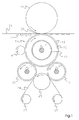
Fig. 1 is a schematic representation, and a sectional view, of a toner fusing assembly of the
invention.
Fig. 2 is a schematic representation, and an enlarged fragmentary sectional view, of an
embodiment of the fuser member of the invention.
Fig. 3 is a schematic representation, and an enlarged fragmentary sectional view, of another
embodiment of the fuser member of the invention.
DESCRIPTION OF THE INVENTION
Copolymers are understood as including polymers incorporating two monomeric units, i.e.,
bipolymers, as well as polymers incorporating three or more different monomeric units, e.g.,
terpolymers, quaterpolymers, etc.
Polyorganosiloxanes are understood as including functional and nonfunctional
polyorganosiloxanes. Poly-organosiloxanes further are understood as including
polydiorganosiloxanes - i.e., having two organo groups attached to each, or substantially
each, or essentially each, of the polymer siloxy repeat units. Polyorganosiloxanes yet further
are understood as including polydimethylsiloxanes.
Functional polyorganosiloxanes are understood as being polyorganosiloxanes having
functional groups on the backbone, connected to the polysiloxane portion, which can
react with fillers present on the surface of the fuser member, or with a polymeric fuser
member surface layer or component thereof. Functional polyorganosiloxanes further are
understood as being polyorganosiloxanes having functional groups such as amino,
hydride, halo (including chloro, bromo, fluoro, and iodo), carboxy, hydroxy, epoxy,
isocyanate, thioether, and mercapto functional groups. Nonfunctional
polyorganosiloxanes further are understood as being polyorganosiloxanes without groups
of the type as indicated.
The term "organo" as used herein, such as in the context of polyorganosiloxanes, includes
"hydrocarbyl", which includes "aliphatic", "cycloaliphatic", and "aromatic". The
hydrocarbyl groups are understood as including the alkyl, alkenyl, alkynl, cycloalkyl, aryl,
aralkyl, and alkaryl groups. Further, "hydrocarbyl" is understood as including both
nonsubstituted hydrocarbyl groups, and substituted hydrocarbyl groups, with the latter
referring to the hydrocarbyl portion bearing additional substituents, besides the carbon and
hydrogen. Preferred organo groups for the polyorganosiloxanes are the alkyl, aryl, and
aralkyl groups. Particularly preferred alkyl, aryl, and aralkyl groups are the C1-C18 alkyl,
aryl, and aralkyl groups, particularly the methyl and phenyl groups.
Fusing or operating temperatures are understood as being within the range of from about
90°C, or about 120°C, or about 150°C, to about 200°C, or about 220°C, or about 250°C.
Preferred temperatures are generally within the range of from about 150°C to about 175°C.
Unless stated otherwise, modulus is measured as tensile modulus of elasticity, using
dynamic mechanical analysis, at a frequency equal to the frequency of the fuser member.
The fuser member frequency pertains to the 360° rotation of the member - in the case of
fuser members that operate in the fusing process by rotation (e.g., fuser members with bases
in the form of cylindrical cores, or of belts on rollers, or of core-mounted plates) - and in
the case of other fuser members, to their equivalent movement.
Unless stated otherwise, molecular weights set forth herein are number average molecular
weights (Mn), measured in Daltons.
Equilibrium surface roughness is the property of a layer whereby the wearing away of the
layer at its surface regenerates a surface with the same, or at least essentially the same,
degree of roughness. Specifically with regard to fuser members, the Equilibrium surface
roughness - of the fuser member's fusing surface layer - is the surface roughness where the
degree of roughness remains unchanged, or essentially unchanged, as use of the fuser
member in the fusing process proceeds. At equilibrium surface roughness, wearing away of
the fusing surface layer at its surface regenerates a surface with the same, or essentially the
same, degree of roughness.
Autoadhesion, with respect to the nonfibrillatable and autoadhesive plastic particles of the
invention, is the property whereby, upon being subjected to dry compounding with a two
roll mill under the conditions set forth herein, the particles will sinter together. Sintering in
this regard is the act of two or more discrete particles becoming fused together into one
particle. During the sintering of two autoadhesive particles, the surface between
them - defining the separation between the particles - becomes indistinguishable; the two
originally distinct particles, previously having no bond or strong physical link or
connection, obtain an adhesion therebetween that is sufficient to prevent them from
separating when dispersed in a solvent and subjected to shear. Particularly, the solvent
preferably does not significantly swell or otherwise dissolve the particles.
Accordingly, autoadhesive particles, under the milling as indicated, will sinter together to
form aggregates that will not uniformly disperse in a solvent. Typical autoadhesive
particles include noncrystalline and semicrystalline materials near or above their glass
transition temperatures at milling conditions. Semi-crystalline materials with very small
amounts of amorphous component may not be autoadhesive. Crystalline materials that
melt or are brought very close to their melt point at milling conditions may be autohesive.
In a particular embodiment, the invention pertains to a layer. This layer may be in the form
of a coating.
The layer of the invention comprises at least one polyfluorocarbon elastomer, or
fluoroelastomer, and plastic particles. Particularly, the layer comprises a polyfluoro-carbon
elastomer, or fluoroelastomer, having nonfibrillatable and autoadhesive plastic particles
dispersed in the layer - preferably, dispersed in the polyfluorocarbon elastomer, or
fluoroelastomer - as filler.
Also as a matter of preference, the layer of the invention is uniform, or at least essentially
uniform, or homogeneous, or at least essentially homogeneous. Especially, the plastic
particles preferably are uniformly, or at least essentially uniformly, dispersed in the layer-correspondingly,
preferably dispersed uniformly, or at least essentially uniformly, in the
polyfluorocarbon elastomer, or fluoroelastomer. And further as a matter of preference, this
uniform - or at least essentially uniform - dispersion is such that surface preparation,
surface finishing, wear during use, or other abrasion, results in the same composition at the
surface of the layer. Particularly, this uniform - or at least essentially uniform - dispersion is
such as to provide the layer with an equilibrium surface roughness.
Yet additionally as a matter of preference, the layer of the invention comprises a layer,
preferably a surface layer, for a suitable article. The invention accordingly can comprise an
article that comprises the indicated surface layer, or an article and a surface layer as
indicated for the article, with the indicated surface layer residing on the article.
In a particular embodiment of the invention, the indicted article comprises a fuser member
for a toner fusing system or process, and the indicated surface layer comprises a fusing
surface layer for the fuser member. In this embodiment the fuser member includes a fuser
base, and further includes the fusing surface layer as indicated overlaying the fuser base.
This fusing surface layer can reside directly on the fuser base. Alternatively, there can be
one or more materials and/or layers, including one or more cushion layers, interposed
between the fuser base and the fusing surface layer.
The plastic particles of the invention are nonfibrillatable and autoadhesive plastic particles.
Particularly as to their nonfibrillatability, during handling and dispersal into the
fluoroelastomer, the particles accordingly will not form reinforcing fibers that raise
viscosity or clog coating devices; further, when the particles are subjected to wear and
abrasion, those at the top of the fusing surface layer do not form fibers that provide
attachment sites for toner melt.
Still additionally in this regard, the plastics of the particles are of low enough molecular
weight so as to be thusly nonfibrillatable. Yet further, they are of high enough molecular
weight so as to retain their shape during handling and dispersal into solvent; this feature
is important for obtaining coatings, and particularly layers, with uniform surface
roughness.
Further regarding the plastic particles of the invention, the plastics are understood as
including noncrosslinked plastics, and also as including resins, particularly inelastic resins,
and crosslinked resins. Fluoroplastics are preferred, as are fluororesins, or nonelastomeric
fluorocarbons.
Fluororesins that are suitable include polytetra-fluoroethylenes (PTFE), and fluorinated
ethylene propylenes (FEP), including copolymers of tetrafluroethylene and hexafluoropropylene,
as well as copolymers of tetrafluroethylene and ethylene, and
copolymers of tetrafluroethylene and perfluoroalkyl vinyl ether (PFA). The
polytetrafluoro-ethylenes are the preferred fluroresins.
PTFE particles have low surface energy, and correspondingly a low propensity for
removing toner from the substrate. They also do not have the abrasiveness of inorganic
filler particles, and therefore do not subject sensors and skives, or other such contacting
elements, to wear. Nevertheless, the PTFE particles themselves impart good wear
resistance to fusing surface layers.
Polytetrafluoroethylenes including one or more additional monomers in minor amounts,
such as up to about 5 mole percent, may be used. Suitable such additional monomers
include fluorocarbons, chlorocarbons, hydrofluorocarbons, hydrochlorocarbons, fluroethers,
and hydrofluroethers, and particularly perfluoroalkylvinylethers. Specific examples are
hexafluoropropylene and n-perfluoropropylvinylether.
Particularly preferred polytetrafluoroethylenes - including those comprising one or more
additional monomers in minor amounts, such as up to about 5 mole percent - are those
having a molecular weight of from about 25,000 to about 250,000. Polytetrafluoroethylenes
in this molecular weight range - i.e., which can be referred to as low molecular weight
(LMW) PTFE - are desirable due to their low cost, and their availability in various
particle sizes, and dry powder form.
Accordingly, the preferred nonfibrillatable and autoadhesive plastic particles of the
invention are nonfibrillatable and autoadhesive polytetrafluoroethylene particles. And the
polytetrafluoroethylenes having a molecular weight of from about 25,000 to about 250,000
are particularly preferred.
A method for preparing LMW PTFE from higher molecular weight
polytetrafluoroethylene is by gamma or electron beam radiation of the latter. Another
method, as discussed herein, is by mechanical shear degradation of the higher molecular
weight polytetrafluoroethylene.
Commercially available LMW polytetrafluoroethylenes which are suitable for the
invention include the following: Zonyl® MP1100, MP1000, and MP1300, from DuPont
Fluoroproducts, Wilmington, DE; Dyneon® 9207, from Dyneon L.L.C., Oakdale, MN;
Algoflon® FSA EX, from Ausimont USA, Inc., Thorofare, NJ; and M270 and M290,
from Shamrock Technologies Inc., Newark, NJ.
The plastic particles - particularly, the PTFE particles - of the invention preferably have a
mean particle diameter of from about 0.05 microns, or about 0.1 microns, to about 20
microns, or about 30 microns, or about 50 microns. In the case of fusing surface layers, a
factor in determining the size of the plastic particles to be used is the surface roughness
which is desired. Smaller particle sizes provide the greatest wear reduction, but also
produce a very smooth coating; particularly, small sized particles, such as in the range of
about 2 microns, will generate a very high gloss, defect free surface. Larger particle sizes
may be used to reduce the coating smoothness, and thus the resulting output image gloss;
particles of sufficient size will provide a low gloss surface. Plastic particles in the form of
indentor particles are suitable for the invention.
The plastic particles can comprise at least about 25 percent by volume, or at least about
30 percent by volume, or at least about 33 percent by volume, or at least about 35 percent
by volume, or at least about 43 percent by volume, of the layer of the invention. Further,
the plastic particles can comprise from about 25 percent by volume, or about 30 percent
by volume, or about 33 percent by volume, or about 35 percent by volume, or about 43
percent by volume, to about 60 percent by volume, or about 64 percent by volume, or
about 65 percent by volume, or about 67 percent by volume, or about 70 percent by
volume, of the layer of the invention.
The layer of the invention can comprise at least about 40 parts, or at least about 50 parts,
or at least about 60 parts, or at least about 150 parts, of plastic particles per 100 parts by
weight fluoroelastomer. Further, the layer of the invention can comprise from about 40
parts; or about 50 parts, or about 60 parts, or about 150 parts, to about 200 parts, or about
220 parts, or about 240 parts, or about 280 parts, or about 300 parts, of plastic particles
per 100 parts by weight fluoroelastomer.
The plastic particles can comprise at least about 26 percent by weight, or at least about 31
percent by weight, or at least about 35 percent by weight, or at least about 40 percent by
weight, either of the combined weight, in the layer of the invention, of the plastic
particles and the fluoroelastomer, or, in the layer of the invention, of the combined weight
of the plastic particles, the fluoroelastomer, and 12 parts MgO per 100 parts by weight
fluoroelastomer. Further, the plastic particles can comprise from about 26 percent by
weight, or about 31 percent by weight, or about 35 percent by weight, or about 40 percent
by weight, to about 66 percent by weight, or about 68 percent by weight, or about 71.4
percent by weight, either of the combined weight, in the layer of the invention, of the
plastic particles and the fluoroelastomer, or, in the layer of the invention, of the combined
weight of the plastic particles, the fluoro-elastomer, and 12 parts MgO per 100 parts by
weight fluoroelastomer.
Particularly with respect to the nonfibrillatable and autoadhesive PTFE particles of the
invention, increasing the proportion of the PTFE particles, in the fusing surface layer of the
invention, results in greater offset resistance for the layer. Resistance to wear also is
improved as the proportion of this PTFE increases, up to and including the range of about
150 parts to about 200 parts per 100 parts by weight fluoroelastomer, and the range of
about 43 percent by volume to about 62 percent by volume, and the range of about 40
percent by weight to about 66 percent by weight - this latter range being based upon the
combined weight as indicated; within these ranges, the highest levels of wear resistance
are achieved.
Optimum wear resistance accordingly occurs at unusually high PTFE proportions. The
improved wear resistance at very high nonfibrillatable and autoadhesive PTFE levels is
completely unexpected.
Specifically, fluoroelastomer fusing surface layers with typical inorganic filler show
increasing wear at filler levels beyond 25 volume percent, whereas for layers with
nonfibrillatable and autoadhesive PTFE, wear rates continue to drop until about the
indicated 150-200 pph, or 43-60 vol.%, or 40-66 wt.% ranges. This result is completely
unexpected, since overpacking the elastomer with fillers typically produces a layer which
has very poor qualities, and often crumbles with handling.
In addition to nonfibrillatable and autoadhesive plastic particles, the layer of the invention
may further include one or more other fillers for one or more other purposes. Different
fillers may be used for such purposes as conducting heat, improving toner offset and
release properties of the fusing surface layer, controlling material properties such as wear
resistance and surface roughness, modifying hardness, and imparting other characteristics,
such as desired mechanical properties, to the fusing surface layer; among the fillers which
may be included are reinforcing fillers.
Particularly, one or more inorganic fillers may be included. Inorganic fillers that may be
used include SnO2, SiC, CuO, ZnO, Al2O3, FeO, Fe2O3, WC, BN, and amorphous silica;
such as precipitated silica and fumed silica.
The inorganic particles preferably have a mean particle diameter of from about 0.1
microns, or about 0.2 microns, to about 20 microns, or about 30 microns, or about 40
microns. Inorganic particles in the form of indentor particles may be used.
However, inorganic filler particles are characterized by high surface energy. As stated, in
fusing surface layers they provide sites to take up toner, and they have the potential of
wearing elements of the toner fusing system, such as sensors and skives, that contact the
fuser member surface; with respect to the matter of offset, the propensity for adherence to
toner can be minimized, but the tendency for toner to stick remains.
Accordingly, particularly with the fusing surface layer of the invention, it is desirable to
minimize the amount of inorganic filler present therein. And particularly to minimize the
tendency of inorganic filler to attract toner offset, it is desirable either, as indicated, that the
amount of inorganic filler be minimized, or that the inorganic filler have been treated with
coupling agent, as discussed.
Inorganic filler therefore may comprise up to about 18 percent by volume, or up to about 20
percent by volume - such as from about 0.5 percent by volume, or about 1 percent by
volume, to about 18 percent by volume, or about 20 percent by volume - of the fusing
surface layer of the invention. However, where the inorganic filler has been treated with
coupling agent, it may comprise up to about 30 percent by volume, more preferably up to
about 25 percent by volume, of the fusing surface layer of the invention. And even in the
case of coupling agent-treated inorganic filler, still more preferably only up to about 20
percent by volume is used.
Yet further, as a matter of particular preference, inorganic filler, whether or not coupling
agent-treated, comprises not more than about 10 percent by volume - more preferably not
more than about 5 percent by volume - of the fusing surface layer of the invention.
The nonfibrillatable and autoadhesive plastic particles, and any other fillers, particularly
inorganic fillers, present in the layer of the invention, may be in one or more of any
suitable shapes - irregular, as well as in the form of spheroids, platelets, flakes, powders,
ovoids, needles, fibers, and the like. With respect to particles employed for the purpose of
providing thermal conductivity, and - for fuser members of the invention, the layer of the
invention being a fusing surface layer - particularly in such instance and where internal
heating is employed, an irregular shape is more preferred, as are spherical particles and
platelets, so as to maximize the heat conducting effect of the filler particles; fibers,
needles, and otherwise elongated shapes are less preferred here, unless they are
advantageously oriented, because in certain alignments they are less effective for properly
conducting heat.
In this regard, elongated particles are more efficient for conducting heat in the proper
direction if they are at right angles to the fuser base - radially aligned, if the fuser base is
a cylindrical core, belt on rollers, or a core-mounted plate, but less efficient if they are
positioned parallel to the core - axially aligned, if the fuser base is a core, a belt, or is
core mounted as indicated. Accordingly, to maximize heat conducting properties where
elongated heat conducting particles are employed, perpendicular (radial) positioning is
preferred, while parallel (axial) alignment may be employed but is not preferred.
Discontinuous phase material can also be included in the layer of the
invention - particularly, in its final form, dispersed in the layer, and especially through the
fluoroelastomer, in the form of domains. Preferably the discontinuous phase comprises at
least one polymer. Preferred polymers for the discontinuous phase are the elastomers.
Among the elastomers that may be used are perfluoro-polyethers, fluoroelastomers, and
particularly silicones, such as fluorosilicones. Suitable silicone elastomers include those that
may be used for the optional one or more cushion layers, as discussed.
Suitable fluoroelastomers include those that may be used for the continuous phase of the
fusing surface layer, as discussed. Where the discontinuous phase comprises a
fluoroelastomer, the fluoroelastomers of the continuous and discontinuous phases must be
such that, at the temperature of the fusing process, the modulus of the fluoroelastomer
continuous phase is greater than the discontinuous phase modulus, and the difference
between the modulus of the fluoroelastomer continuous phase and the modulus of the
discontinuous phase is sufficiently great, and the modulus of the discontinuous phase is
sufficiently low, so that the requisite gloss level is achieved, as discussed.
The discontinuous phase material can be provided, for use in preparing the fusing surface
layer, already in final form, and in this final form, serve as the domains dispersed in
fluoroelastomer. Particularly, the discontinuous phase material may be provided already in
particulate form.
In this regard, the elastomers as indicated may be provided as preformed particles.
Particularly, preformed silicone elastomer particulate may be used. The silicone elastomer
particles are crosslinked particles of polydiorganosilixane, preferably
polydimethylsiloxane, elastomer.
The silicone elastomer particulate can be prepared by emulsion polymerization, or from
bulk silicone by grinding, or otherwise reducing the material to discrete particles.
Particularly, the crosslinked polydiorganosilixane - e.g., polydimethylsiloxane - particles
can be obtained using condensation or addition cure methods. Preparation preferably
involves the reaction of a vinyl dimethyl terminated poly-dimethylsiloxane having a number
average molecular weight of from about 2,000 to about 20,000, and either a
polymethylhydrosiloxane or a methyl hydro, dimethylsiloxane copolymer, having a number
average molecular weight of from about 300 to about 3,000; also as a matter of preference,
the ratio of hydride to vinyl groups is from about 1:1 to about 2:1.
The silicone elastomer particles particularly can be prepared in accordance with the
procedures set forth in U.S. Patent No. 6,281,279; accordingly, the silicone elastomer
particles as disclosedin U.S. Patent No. 6,281,279 can be used
In a preferred embodiment, the silicone elastomer particles are in a core-shell configuration,
comprising a silicone resin shell surrounding the silicone elastomer core. The shell is
expected to provide the particle with a surface of higher hardness to the particle, which will
also have a higher surface energy. This surface treated preformed silicone particulate may
have better adhesion with the surrounding elastomer matrix, while retaining the advantage
of added silicone rubber.
The surface treatment, to provide the shell portion of the core-shell configuration, can be
performed
in situ by adding an aminosilane to the coating preparation. The amount of
aminosilane added is from about 0.1 percent by weight to about 5 percent by weight of the
silicone particles. Preferably the aminosilane has the formula
wherein
Commercially available silicone particulates that are suitable for the invention include 52-854,
X-52-875, KMP597, and KMP598, from Shin-Etsu Silicones of America, Inc., Akron,
OH. A commercially available core-shell configuration silicone particulate that is suitable is
KMP600, also from Shin-Etsu Silicones.
The material - e.g., the one or more polymers - that becomes the discontinuous phase,
particularly elastomers used for this purpose, may be employed in cured form, or in curable
form, such as a curable liquid or gum. Where employed in curable form, the material is
cured by the curing of the fusing surface layer of the invention, to provide the discontinuous
phase domains; particularly, the curing of the layer effects crosslinking of curable polymer
that is present.
Among the curable silicone elastomers that may be employed are peroxide cure silicone
elastomers and vinyl addition cure silicone elastomers. Particularly preferred for the
discontinuous phase are the curable siloxane polymers, particularly the curable
polyfunctional poly(C1-6 alkyl) siloxane polymers, disclosed in U.S. Patent No. 5,582,917.
A preferred commercially available curable siloxane polymer is SFR-100 silicone, from GE
Silicones, Waterford, NY. SFR-100 silicone is characterized as a silanol- or trimethylsilyl-terminated
polymethylsiloxane, and is a liquid blend comprising about 60-80 weight percent
of a difunctional polydimethylsiloxane having a number average molecular weight of about
150,000, and 20-40 weight percent of a polytrimethylsilyl silicate resin having
monofunctional (i.e. trimethylsiloxane) and tetrafunctional (i.e. SiO2) repeating units in an
average ratio of between about 0.8 and 1 to 1, and having a number average molecular
weight of about 2,200.
The curable elastomers, and particularly the curable siloxane polymers, can be employed in
the amount of up to about 50 parts, or up to about 60 parts, or up to about 80 parts, per 100
parts by weight of the fluoroelastomer. Particularly, the curable elastomers, and more
particularly the curable siloxane polymers, may be used in the amount of from about 5 parts,
or about 10 parts, to about 50 parts, or about 60 parts, or about 80 parts, or about 100 parts,
per 100 parts by weight of the fluoroelastomer.
At fuser operating conditions, or at the temperature of the fusing process, or at the fusing
temperature, the domains of the discontinuous phase preferably have a modulus of about
8 X 10⁶ Pa or less, or about 10 X 106 Pa or less, or from about 0.5 X 10⁶ Pa, or about 0.8
X 106 Pa, or about 1 X 10⁶ Pa, to about 4 X 10⁶ Pa, or about 8 X 10⁶ Pa, or about 10 X
106 Pa. The discontinuous phase domains preferably have a mean diameter - particularly
in the case of the particulate, a mean particle diameter - of from about 0.1 microns, or
about 0.2 microns, or about 0.5 microns, or about 1 micron, to about 30 microns, or about
40 microns, or about 50 microns, or about 60 microns, or about 80 microns.
Domain size - particularly where preformed particles are employed, and especially in the
case of silicone elastomer particulate - may be used to control the surface roughness of the
layer, and accordingly, with fusing surface layers of the invention, the gloss of images
produced in the toner fusing process. Corresponding to how the size of the non-fibrillatable
and adhesive plastic particles affects the invention, smaller silicone elastomer particle sizes,
particularly in the range of about 0.1 to 2.0 microns, will contribute to providing smoother
surfaces and higher gloss, while larger silicone elastomer particle sizes will help in reducing
smoothness and image gloss.
The discontinuous phase can be present, in the fusing surface layer, in an amount of from
about 10 parts, or about 20 parts, or about 30 parts, or about 40 parts, or about 50 parts, to
about 80 parts, or about 100 parts, or about 120 parts, or about 150 parts, per 100 parts by
weight of the fluoroelastomer continuous phase. Also, the fusing surface layer can comprise
at least about 20 parts, or at least about 30 parts, or at least about 40 parts, or at least about
50 parts, discontinuous phase per 100 parts by weight of the fluoroelastomer continuous
phase. Yet additionally, the discontinuous phase can comprise at least about 10 percent by
volume, or at least about 15 percent by volume, or at least about 20 percent by volume, or at
least about 25 percent by volume, or at least about 30 percent by volume, or at least about
35 percent by volume, or at least about 40 percent by volume, of the fusing surface layer.
The material for forming the discontinuous phase - provided already in final form, or
provided in curable form, to be cured to form the domains - can be included with the
fluoroelastomer composition that is added to the solvent. However, preferably the material
for forming the discontinuous phase is added to the solvent separately from the
fluoroelastomer composition, as discussed herein.
The nonfibrillatable and autoadhesive plastic particles of the invention are insoluble in the
solvents used for preparing the coating preparations of the invention; in this regard, the
nonfibrillatable and autoadhesive plastic particles must be insoluble even to the extent that
the solvents cannot make the particles adhere to one another due to softening. Preferably,
discontinuous phase material that, when employed, is already in final form - e.g., preformed
particulate - and any other fillers, particularly inorganic fillers, that are employed, also are
insoluble in the indicated solvents; these optional materials preferably also are insoluble
even to the extent that the solvents cannot make the particles adhere to one another due to
softening.
Yet additionally, the nonfibrillatable and autoadhesive plastic particles of the invention,
and the indicated final form discontinuous phase material and any other fillers that are
employed, are heat stable at fusing or operating temperatures. Particularly, these materials
preferably are heat stable at fusing process temperatures - e.g., within the range of from
about 90°C, or about 120°C, or about 150°C, to about 200°C, or about 220°C, or about
250°C. Accordingly, the discontinuous phase material and filler preferably are heat stable
at temperatures of up to at least about 90°C, more preferably up to at least about 120°C,
still more preferably up to at least about 150°C, still more preferably up to at least about
200°C, still more preferably up to at least about 220°C, or even up to at least about
250°C.
This heat stability entails the absence, or at least the essential absence or substantial
absence, of degradation, decomposition, sublimation, and release of byproducts, and of
change in shape, size, or state of matter. And indentor particles, where employed, in
addition to being thusly heat stable, also undergo no melting, or essentially or
substantially no melting, at the temperatures as indicated.
For improving the wear resistance and release properties of the layer, particularly the fusing
surface layer, of the invention, one or more of the materials which are used for preparing the
layer of the invention, and which are reactive with SiOH groups, may be compounded with
a coupling agent - preferably a silane coupling agent, as discussed in U.S. Patent No.
5,998,033. Materials suitable for this treatment include inorganic fillers and cocuratives.
As to this matter, herein it is disclosed that the materials which are compounded, for
subsequent combination with solvent and formation of the layer of the invention, include
the fluoroelastomer. Where the layer also incorporates inorganic filler particles, they as well
are included in the dry compounding treatment. And if cocurative additionally is being
employed, it also may be included in this treatment. Accordingly, where one or more SiOH
group-reactive materials, as indicated, are present, the requisite amount of coupling agent
yet additionally can be included in the compounding of these materials.
Instead of compounding with coupling agent, one or more of the SiOH group-reactive
materials may be surface treated with a coupling agent - here also preferably a silane
coupling agent, as discussed in U.S. Patents Nos. 5,935,712, 6,090,491, and 6,114,041. The
coupling agent can be dissolved in an appropriate solvent, and surface treatment can be
effected by steeping the material in this solution; ultrasonication can be employed during
this treatment. After treatment the material is washed and dried. In the case of silane,
preferably the treatment solution is prepared by adding about 2 weight percent of this
coupling agent to a solvent comprising 95 percent by volume ethanol and 5 percent by
volume water, and stirring for ten minutes. The material is covered by the solution and
ultrasonicated for ten minutes. The material then is separated by vacuum filtration, rinsed
with ethanol, and thereafter oven dried at 150°C, for 18 hours under reduced pressure
(vacuum).
It is understood that both the surface treatment and the compounding, as discussed, are
included in referring to treatment with coupling agent. It is further understood that both
material compounded with coupling agent, and material surface treated with coupling agent,
are included in referring to the resulting product as coupling agent-treated material.
Particularly as to the silane coupling agents, 3-aminopropyltriethoxysilane is a silane which
may be employed. However, the secondary amine functional silanes are preferred, because
they have relatively less of an unfavorable impact upon pot life. Suitable secondary amine
functional silanes include N-phenylaminopropyltrimethoxysilane, N-phenylamino-propyltriethoxysilane,
3-[2-N-benzylaminoethylaminopropyl-trimethoxysilane, and 3-[2-N-benzylaminoethylaminopropyl-triethoxysilane.
Also among the silanes that may be used are
the styryl-functionalized silane coupling agents disclosed in U.S. Patent No. 6,090,491.
The treatment with coupling agent serves to improve layer wear resistance and release
properties. This treatment therefore has particular utility for the fusing surface layer of the
invention.
Yet other additives and adjuvants also may be used with the fluoroelastomer, as long as they
do not affect the integrity thereof, or significantly interfere with an activity intended to occur
in the layer - such as the crosslinking of the fluoroelastomer. These further additives and
adjuvants, where present, are provided in amounts and proportions as are generally known
or as can be determined without undue experimentation by those of ordinary skill in the art.
Suitable examples include crosslinking agents, processing aids, accelerators, polymerization
initiators, and coloring agents.
Particularly with respect to the toner fusing system and the toner fusing process - and
correspondingly the fuser member - of the invention, the fuser base may be any of those as
are known in the art. As a suitable embodiment, the fuser base may be a core in the form of
a cylinder or a cylindrical roller, particularly a hollow cylindrical roller. In this embodiment
the fuser base may be made of any suitable metal, such as aluminum, anodized aluminum,
steel, nickel, copper, and the like. Also appropriate are ceramic materials and polymeric
materials, such as rigid thermoplastics, and thermoset resins with or without fiber
enforcement. Preferably the roller is an aluminum tube or a flame sprayed aluminum coated
steel tube.
Alternatively, the fuser base may be a plate. Materials suitable for the core may also be
used for the plate.
One embodiment of a fuser base in the plate form is a curved plate mounted on a larger
cylindrical roller - that is, larger than a cylindrical roller which itself is employed as a
fuser core. Being thusly curved, the plate accordingly has the shape of a portion of a
cylinder. Additionally, the plate can be removably mounted on the cylindrical roller, so
that the plate can be replaced without also requiring replacement of the roller. In this
embodiment, the properties discussed herein with reference to the fuser base pertain only
to the portion of the cylindrical roller occupied by the attached plate; the rest of this roller
is not involved in the fusing of toner to substrate.
As yet another alternative, the fuser base may be a belt, particularly an endless flexible belt.
A thin belt made of a suitable metal, such as those indicated for the core and plate forms;
the belt may also be made of a polyamide or a polyimide, particularly a heat resistant
polyamide or polyimide. A polyimide material appropriate for the belt is commercially
available under the trademark Kapton, from DuPont High Performance Films, Circleville,
OH.
Preferably the belt is mounted on rollers, which can be cores of the type as discussed herein.
As a matter of preference two rollers are utilized with the belt, each of these two rollers
defining a different one of the curves around which the belt passes.
A support member for the fusing system and process likewise may be any of those as are
known in the art; particularly, it can be a backup roller, also referred to as a pressure roller.
The support member can be in the form of a roller, plate, or belt, in the same manner as is
suitable for the fuser base; particularly, cores suitable for the fuser member may also be
used for the support member. Where the support member is a belt, preferably it is
mounted on rollers, in the same manner as - for the fuser base in the form of a belt.
In any of the indicated forms, the support member may have mounted thereon a cushion
for forming the nip with the fuser member. Suitable cushion materials include those
having at least some degree of temperature resistance, such as silicone and EPDM
elastomers. In the absence of yet a further layer in turn being mounted on the cushion, this
cushion also serves to contact the substrate, and accordingly to cooperate with the fuser
member.
Alternatively or in addition to the cushion, the support member may have mounted
thereon a thin fluoroplastic surface layer, such as a Teflon or PFA layer, overlaying the
surface that cooperates with the fuser member. Where both the cushion and the thin
fluoroplastic surface layer are present on the support member, the cushion is situated
between the support member and the surface layer.
Preferably the fuser base is in the form of a cylindrical roller, with the fuser member
correspondingly in the form of a roller - specifically, a fuser roller. Also as a matter of
preference, the support member comprises a backup roller.
Further in the toner fusing system and process of the invention, internal heating and/or
external heating may be employed. Heating means as are known in the art are suitable.
Preferably, the means of providing heat for fusing toner and substrate comprise the heating
of the fuser member by one or more external and/or internal heating sources, and
transmission of this heat from the fuser member to the toner, or to both toner and
substrate - preferably by contact.
Where there are one or more materials and/or layers, including one or more cushion layers,
interposed between the fuser base and the fusing surface layer, they may be those as are
known in the art. Where there is at least one cushion layer, the at least one cushion layer can
include one or more thermally conductive cushion layers and/or one or more thermally
nonconductive cushion layers.
When used, the at least one cushion layer particularly can be that as disclosed in U.S.
Application No. 09/879,585, filed June 12, 2001.Generally, the thickness of the at least
one cushion layer is about 20 millimeters or less, preferably from about 1 to about 10
millimeters.
Among the materials which can be used for the at least one cushion layer are suitable
silicone elastomers, such as appropriate thermally conductive silicone elastomers and
thermally nonconductive silicone elastomers. Addition cure, condensation cure, and
peroxide cure silicone elastomers can all be used, with addition cure silicone elastomers
and condensation cure silicone elastomers being preferred.
Further, silicone elastomers formulated as room temperature vulcanizate (RTV), liquid
injection moldable (LIM), and high temperature vulcanizate (HTV) silicone elastomers
can be used. RTV and LIM silicones are preferred.
A highly desired property for the silicone elastomers is heat stability. Particularly for
cushion layer silicone elastomers, this property is characterized by low compression set,
resistance to hardening or softening over time, and resistance to tear propagation from
heat aging.
In particular, compression set is permanent deformation. Low compression set, or good
compression set resistance, is required for the desired shape of the fuser roller to be
maintained.
Two particular silicone elastomers which may be used are Silastic™-J silicone, from Dow
Coming Corporation, Midland, MI, and a silicone commercially available under the
designation EC4952 from Emerson & Cuming ICI, Billerica, MA.
In a process which may be used for application of at least one cushion layer, the fuser base
optionally can first be degreased and surface roughened. If these functions are performed,
they may be accomplished by grit blasting. Except as discussed otherwise herein, the
fuser base surface, whether or not initially degreased and roughened, is primed with
conventional primer, such as Dow™ 1200 RTV Prime Coat primer, from Dow Corning
Corporation, and material for forming a cushion is subsequently applied thereto.
To form a cushion layer, silicone elastomer is molded, particularly by injection, or
extruded or cast onto the fuser base to the desired thickness. Curing is then effected. For a
RTV silicone, this is accomplished by allowing it to sit at room temperature.
After curing, conventionally the silicone layer is subjected to a post cure, which improves
compression set resistance. Typically a post cure is conducted at a temperature of around
200°C, or about 150-200°C, or about 200-230°C, or as high as about 240°C, for a period
of about 1-2 hours, or for about 4 hours, or for about 24 hours, or for a period of about 4-48
hours.
Each silicone cushion layer is subjected to cure, and preferably also to post cure, before
application of the next layer, except in the case of the last silicone layer to be laid down.
For this finally applied silicone cushion layer, the coating preparation for forming the
fusing surface layer is first laid down and then cured at a raised temperature for a period
of time, as discussed.
This curing of the coating preparation serves as the post cure for the silicone cushion
layer on which it is deposited. Delaying the post cure of the last cushion layer in this
manner allows maximum adhesion between the cushion and the fusing surface layer to
develop.
Where only one silicone cushion layer is employed, since it is also the last cushion layer
to be laid down, it is not post cured until the coating preparation is applied, in accordance
with the foregoing.
Before the coating preparation for forming the fusing surface layer is applied, the cushion
material can be ground to a desired profile, depending upon the paper handling concerns
to be addressed. For instance, a cylinder shape, or a crown, or barrel, or bow tie, or
hourglass profile may be provided.
Addition cure silicone elastomers typically employ a platinum catalyst; condensation cure
silicone elastomers, a tin catalyst. Tin catalysts will poison platinum catalysts, but the
reverse is not true. Accordingly, where sequential addition and condensation cure silicone
elastomer layers are employed, a condensation cure layer can be applied onto an addition
cure layer, but not vice versa.
Suitable fluoroelastomers for the layer of the invention include random polymers
comprising two or more monomeric units, with these monomeric units comprising
members selected from a group consisting of vinylidene fluoride [-(CH2CF2)-],
hexafluoropropylene [-(CF2CF(CF3))-], tetrafluoroethylene [-(CF2CF2)-],
perfluorovinylmethyl ether [-(CF2CF(OCF3))-], and ethylene [-(CH2CH2)-]. Among the
fluoroelastomers that may be used are fluoroelastomer copolymers comprising vinylidene
fluoride and hexafluoro-propylene, and terpolymers as well as tetra- and higher polymers
including vinylidene fluoride, hexafluoropropylene, and tetrafluoroethylene monomeric
units. Additional suitable monomers include perfluorovinylalkyl ethers, such as
perfluorovinylmethyl ether.
Preferred fluoroelastomers include random polymers comprising the following monomeric
units:
-(CH2CF2)x-, -(CF2CF(CF3))y-, and -(CF2CF2)z-,
wherein
Further preferred fluoroelastomers are random polymers comprising the following
monomeric units:
-(CH2CH2)x-, -(CF2CF(OCF3))y-, and -(CF2CF2)z-,
wherein
The fluoroelastomers, as discussed, may further include one or more cure site monomers.
Among the suitable cure site monomers are 4-bromoperfluorobutene-1, 1,1-dihydro-4-bromo-perfluorobutene-1,3-bromoperfluorobutene-1,
and 1,1-dihydro-3-bromoperfluoropropene-1.
When present, cure site monomers are generally in very small
molar proportions. Preferably, the amount of cure site monomer will not exceed about 5
mole percent of the polymer.
The fluoroelastomer molecular weight is largely a matter of convenience, and is not critical
to the invention. However, as a matter of preference, the fluoroelastomers have a number
average molecular weight of from about 10,000 to about 200,000. More preferably they
have a number average molecular weight of from about 50,000 to about 100,000.
Commercially available fluoroelastomers which may be used are those sold under the
trademark Viton® by Dupont Dow Elastomers, Stow, OH; they include Viton® A, Viton®
B, Viton® E, Viton® GF, Viton® GH, Viton® GFLT, Viton® B 50, Viton® B 910,
Viton® E 45, Viton® E 60C, and Viton® E 430. Also suitable are the Tecnoflons®, such
as T838K, FOR-THF, FOR-TFS, FOR-LHF, NM, FOR-60KIR, TH, TH505, and
FOR4391, from Ausimont USA, Inc., Thorofare, NJ, and the Fluorel™ fluoro-elastomers,
such as FE5840Q, FX9038, FX2530, FLS5840Q, FLS2690, FC2230, FC2145, FT2430,
Fluroel 2170, Fluorel 2174, Fluorel 2177, Aflas (a polypropylene-tertafluoroethylene), and
Fluorel II L11900 (a polypropylene-tetrafluoroethylene vinylidene fluoride), from Dyneon
L.L.C., Oakdale, MN.
Appropriate fluoroelastomers include those as identified in U.S. Patents Nos. 4,372,246,
5,017,432,5,217,837, and 5,332,641.
The Viton® A, Viton® GF, FE5840Q, and FX9038 fluoro-elastomers are particularly
preferred.
Fluoroelastomer preferably comprises from about 20 percent by volume to about 70 percent
by volume of the fluoroelastomer compositions used to prepare coating preparations of the
invention. Fluoroelastomer likewise preferably comprises from about 20 percent by volume
to about 70 percent by volume of layers of the invention.
For preparation of the layer of the invention, one or more curing agents or curatives are
employed in a suitable amount to effect curing of the fluoroelastomer. Suitable curatives for
the fluoroelastomer include nucleophilic addition curing systems. Also appropriate as
curatives are free radical initiator curing systems.
Preferred nucleophilic addition curing systems for the fluoroelastomer are the bisphenol
curing systems. These preferably include at least one bisphenol crosslinking agent and at
least one accelerator.
Suitable bisphenol crosslinking agents include 4,4-(hexafluoroisopropylidene)diphenol, also
known as bisphenol AF, and 4,4-isopropylidenediphenol. Accelerators which may be
employed include organophosphonium salt accelerators such as benzyl
triphenylphosphonium chloride.
The amount of bisphenol crosslinking agent used, and likewise the amount of accelerator
used, each is preferably from about 0.5 parts to about 10 parts per 100 parts by weight of the
fluoroelastomer. A bisphenol curing system, taken as a whole, is employed in an amount,
based on the total weight of crosslinking agent and accelerator, likewise of from about 0.5
parts to about 10 parts per 100 parts by weight of the fluoroelastomer. A commercially
available bisphenol curing system which may be used is Viton® Curative No. 50 from
Dupont Dow Elastomers, which is a combination of bisphenol AF and one or more
quaternary phosphonium salt accelerators; this curative preferably is used in an amount of
from about 2 parts to about 8 parts per 100 parts by weight of the fluoroelastomer.
Further nucleophilic addition curing systems are polyfunctional hindered curing systems,
particularly diamine curing systems. Among the diamine curing systems that may be
employed are diamine carbamate curing systems. Examples of these are
hexamethylenediamine carbamate and N,N'-dicinnamylidene-1,6-hexanediamine; these are
commercially available as DIAK No. 1 and DIAK No. 3, respectively, from E.I. Du Pont de
Nemours, Inc. DIAK No. 4 is another polyfunctional hindered diamine curing system that
may be used.
Free radical initiator curing systems which may be used include peroxide free radical
initiator curing systems. Preferably these comprise at least one peroxide free radical
initiator, and at least one suitable crosslinking agent; peroxides that may be employed for
this purpose include the suitable aliphatic peroxides.
Particular peroxides which may be used include ditertiary butyl peroxide, dicumyl peroxide,
2,4-dichlorobenzoyl peroxide, 2,5-dimethyl-2,5-di(t-butyl peroxy)hexane, dibenzoyl
peroxide and the like. Particular crosslinking agents suitable for these systems include
triallyl cyanurate, triallyl isocyanurate, and others known in the art.
Where the curative comprises a nucleophilic addition curing system or a free radical
initiator curing system, one or more cocuratives may also be employed. In this regard, the
use of these systems for curing fluoroelastomers can generate hydrogen fluoride.
Accordingly, acid acceptors for neutralizing the hydrogen fluoride are suitable cocuratives.
Preferred examples of these acid acceptors are the Lewis bases, particularly inorganic bases
such as alkali and alkaline earth metal bases. Preferred bases include magnesium oxide, zinc
oxide, lead oxide, calcium oxide, and hydroxides including calcium hydroxide, magnesium
hydroxide, potassium hydroxide and sodium hydroxide. Hydrides may also be employed
including sodium borohydride and lithium aluminum hydride.
Also suitable as a cocurative is the cocurative system disclosed in U.S. Application No.
09/450,302, filed November 29, 1999.
The amount of cocurative which is used preferably is from about 1 part, or about 2 parts, to
about 20 parts, per 100 parts by weight of the fluoroelastomer. Particularly where one or
more acid acceptors are employed, the amount used is preferably that which is sufficient to
neutralize the indicated hydrogen fluoride and allow for complete crosslinking.
An excessive amount of cocurative, particularly in the case of the more basic curatives such
as calcium hydroxide, will shorten the life of the coating solution used to prepare the layer
of the invention, as discussed herein. Specifically, cocurative excess will cause rapid
viscosity increase and solution gellation.
Magnesium oxide, calcium hydroxide, and zinc oxide are preferred acid acceptors.
Particularly for solution coatings, magnesium oxide and zinc oxide are preferred acid
acceptors.
A fluoroelastomer composition, used for making the coating preparation of the invention,
can comprise the fluoro-elastomer, and also can include one or more of those of the
curative, cocurative, adjuvant, and additive components that are being employed. In a
preferred embodiment, the fluoroelastomer composition comprises the fluoroelastomer and
cocurative.
And where filler other than the nonfibrillatable and autoadhesive plastic
particles - particularly, inorganic filler - is being employed, this other filler yet additionally can be
included in the fluoroelastomer composition. The nonfibrillatable and autoadhesive plastic
particles of the invention are not included in the fluoroelastomer composition.
The fluoroelastomer composition may be formed by any means suitable for combining the
components. An appropriate method of mechanical milling or incorporation, or
compounding, and particularly a dry compounding method, is preferred, such as two roll
milling or shear mixing, as in an internal mixer like a Banbury® mixer, from Farrel
Corporation, Ansonia, Connecticut.
Dry compounding most preferably is conducted with a two roll mill. It may be carried out at
a temperature of from about 40°F to about 200°F, or from about 50°F to about 100°F.
However, preferably the compounding is carried out at approximately room temperature, for
example, from about 50°F to about 70°F (from about 10°C to about 21°C), more preferably
from about 55°F to about 65°F (from about 13°C to about 28°C). This operation tends to
generate heat, so preferably a mill with its operating temperature inhibited by some means,
such as by water cooling, is employed. The materials are compounded until a uniform, dry,
flexible composite sheet is obtained.
Commercially provided fluoroelastomers often come with curatives already incorporated
therein. However, for solution coating it is preferred that the curative not be provided in this
manner, but rather be employed as a separate component.
Although curative, as such a separate component, may be included in the fluoroelastomer
composition - e.g., dry compounded with the other indicated components - preferably it is
not, but rather is separately added to the one or more solvents to which the fluoroelastomer
composition and nonfibrillatable and autoadhesive plastic particles also are added.
Particularly, the curative preferably is added directly to the coating preparation prior to
coating. Withholding the curative thusly for addition to the final coating preparation greatly
extends the shelf life of this preparation.
For forming the requisite layer on the fuser member, the fluoroelastomer composition and
the nonfibrillatable and autoadhesive plastic particles both are combined with suitable
solvent. Specifically in the case of the fluoroelastomer composition obtained from dry
compounding, this composition is divided into pieces; being thusly in pieces, the fluoro-elastomer
composition, and the indicated plastic particles, are added to a sufficient amount
of the indicated suitable solvent, which comprises one or more solvents, to provide a
coating preparation - particularly a solution, which is suitable for use as a coating.
The plastic particles and the fluoroelastomer composition are added to the solvent
separately. In being added separately, they may be added simultaneously, but preferably the
plastic particles are added either before or after the addition of the fluoroelastomer
composition.
Further components may also be employed. Although they can be included in the
preparation of the fluoroelastomer composition, preferably they are added to the solvent.
For instance, discontinuous phase material, where employed, may be included at this point.
In fact, whether provided in final form - e.g., as preformed particulate - or in curable form
- like the curable siloxane polymers discussed herein, to be crosslinked by the curing of the
layer of the invention - preferably the discontinuous phase material is added directly to the
solvent.
Further, one or more of the polydiorganosiloxane oligomers, particularly the α,ω
difunctional polydiorgano-siloxanes, disclosed in U.S. Patent No. 4,853,737. These
polydiorganosiloxanes may be employed in the amount of from about 0.1 grams to about 5
grams per 100 grams of solution.
If both curable siloxane polymer and polydiorgano-siloxane oligomer, as discussed, are
employed, it is preferable that they be kept separate prior to addition to the fluoroelastomer,
because the polydiorganosiloxane oligomers catalyze the crosslinking of the curable
siloxane polymers.
Yet additionally, one or more yet additional additives and/or adjuvants can be added to the
solution, such as defoaming agents, wetting agents, and other materials. These yet
additional adjuvants and fillers, where present, are provided in amounts and proportions as
are generally known or as can be determined without undue experimentation by those of
ordinary skill in the art.
The amount of solvent used is preferably that which will provide a solution having a solids
content of from about 5 weight percent to about 50 weight percent, more preferably from
about 10 weight percent to about 30 weight percent.
Water is not employed as a solvent with the present invention; the one or more solvents of
the invention are nonaqueous solvents. Accordingly, water is absent, or at least essentially
absent, from the solvent or solvents, and from the solution formed therefrom, and thusly
from the coating preparation.
Suitable solvents include polar solvents and organic solvents, and particularly solvents
which are both polar and organic, such as ketones, esters, and acetates. Ketones that can be
used include acetone, methyl ethyl ketone (MEK), and methyl isobutyl ketone. Preferred
esters are the C1-C8 acetates, such as the C2-C8 acetates - e.g., ethyl acetate, n-propyl
acetate, isopropyl acetate, n-butyl acetate, isobutyl acetate, t-butyl acetate, and sec-butyl
acetate.
As indicated, one or more solvents may be employed. Particularly, a mixture of two or more
solvents can be used.
For instance, a solvent that can be used is one comprising about 50 weight percent each of
methyl ethyl ketone and methyl isobutyl ketone. Yet other solvents which may be used are
blends of methyl ethyl ketone and methanol (MeOH), such as blends comprising about 85
percent by weight methyl ethyl ketone and about 15 percent by weight methanol (85:15
MEK:MeOH). Methanol is used to extend the solution life of the coating, or to improve the
coating quality.
Further in this regard, a very long solution life, without the formation of a gel, can be
obtained where the solvent comprises at least about 80 percent by weight of one or more
acetates. More preferably here, the one or more acetates comprise at least about 85 percent
by weight of the solvent. And still more preferably, the solvent consists of, or consists at
least essentially of, one or more acetates.
One or more solvents other than acetates thusly can be used together with the indicated one
or more acetates. Solvents suitable for this purpose include MeOH, and also all of the
solvents, besides acetates, that are suitable for the present invention. The preferred solvents
for use with one or more acetates are MeOH and MEK.
Moreover, with respect to inorganic filler and/or cocurative which has been treated with
coupling agent - particularly silane coupling agent - as discussed, the presence of this
treated inorganic filler and/or cocurative will not unfavorably affect solution properties,
such as the long solution life provided by the at least 80 percent by weight acetate solvent.
However, in the case of inorganic filler that is not coupling agent-treated, if too much of this
thusly untreated inorganic - particularly metal oxide - filler is used, then there will be an
adverse result.
Specifically, untreated inorganic filler will not unfavorably affect solution life. But the
presence of inorganic filler not treated with coupling agent, in amounts beyond a certain
proportion, will reduce wear resistance - i.e., will cause the wear resistance, of the coating
or layer formed from the solution, to be reduced - as compared to the wear resistance of
coatings or layers derived from similar solutions having ketone solvents.
And the wear resistance reduction will occur even with the untreated inorganic filler being
provided as part of the fluoroelastomer composition. Particularly, the reduction in wear
resistance takes place even despite dry compounding of the inorganic filer with the
fluoroelastomer, before addition to the indicated acetate solvent.
The reason for this adverse effect is not fully understood. However, it is believed that the
reduced wear resistance is due to a high affinity of the solvent for the filler surface, with the
acetate thought to interact strongly with the high surface energy filler, and interaction
between the filler and the fluoroelastomer thereby being reduced. Surface treatment of the
inorganic - particularly, metal oxide - filler may provide a barrier, improve interaction with
the fluoroelastomer, or otherwise prevent the solvent from reducing the interaction of the
fluoroelastomer with the filler particles.
So to preserve wear resistance, where the at least about 80 percent acetate solvent is
employed, the amount of untreated inorganic filler must be kept to within certain limits. In
this regard, with solvent comprising at least about 80 percent by weight acetate, and where
inorganic filler not treated with coupling agent is being used, if the amount of the untreated
inorganic filler is such that this untreated filler will comprise not more than about 10
percent by volume, preferably not more than about 5 percent by volume, of the layer
prepared from the solution, then the untreated filler should have little or no impact on wear
properties. This is also the case where the amount of cocurative - particularly where the
cocurative comprises one or more of magnesium oxide, magnesium hydroxide, and zinc
oxide - that is being employed comprises from about 1 part, or from about 2 parts, to about
20 parts, per 100 parts by weight of the fluoroelastomer.
Accordingly, with a solution where the solvent comprises at least about 80 percent by
weight acetate, and where inorganic filler that has not been treated with coupling agent is
included, the amount of this untreated inorganic filler in the solution preferably will be such
that it comprises about 10 percent or less by volume, more preferably about 5 percent or less
by volume, of the layer of the invention prepared from the solution. Particularly, where the
solvent comprises at least about 80 percent by weight acetate, and where cocurative is being
employed in the amount of from about 1 part, or from about 2 parts, to about 20 parts, per
100 parts by weight of the fluoroelastomer, then here also the amount of the untreated
inorganic filler preferably will be such that it comprises about 10 percent or less by volume,
more preferably about 5 percent or less by volume, of the layer of the invention prepared
from the solution.
Further where the solvent comprises at least about 80 percent by weight acetate and
inorganic filler not treated with coupling agent is included, the sum - of the amount of the
untreated inorganic filler and the amount of cocurative also not treated with coupling agent
- preferably will be such that the combined amount of untreated filler and untreated
cocurative comprises about 15 percent or less by volume of the layer of the invention
prepared from the solution. More preferably the sum of untreated filler and untreated
cocurative will be such that their combined amount comprises about 10 percent or less by
volume of the layer.
And as a matter of particular preference where the solvent comprises at least about 80
percent by weight acetate, cocurative is used - preferably comprising one or more of
magnesium oxide, magnesium hydoxide, and zinc oxide - and the cocurative may be treated
with coupling agent or may be untreated, but otherwise there is no employment of inorganic
filler, particularly metal oxide filler, that is not treated with coupling agent. Accordingly, the
untreated inorganic filler as indicated preferably is absent, or at least essentially absent,
from the solution, and from the layer of the invention formed from the solution.
Also as a matter of particular preference with respect to the foregoing, there is no
employment of the inorganic filler - again, particularly metal oxide filler - that is treated
with coupling agent. Correspondingly - and here also, apart from the treated cocurative
which may be employed - treated inorganic filler as indicated preferably is absent, or at least
essentially absent, from the solution, and from the layer of the invention formed from the
solution.
The foregoing 80 percent or greater acetate solutions of the invention provide coating
preparations having excellent solution life, remaining coatable for up to 120 hours, or
longer, after the curative has been added to the solution. Excellent solution life is
maintained where no alcohol is used - although as indicated, MeOH is one of the solvents
that can be employed with the one or more acetates. Further, coatings and layers prepared
from these coating preparations are uniform and of high quality.
The combination or mixture that comprises solvent, fluoroelastomer composition, and
nonfibrillatable and autoadhesive plastic particles, and that can further comprise one or
more additional components as indicated, is subjected to mixing under high shear - i.e., to
high shear mixing - to form the solution as discussed. This high shear mixing is mixing that
breaks up all, or at least essentially all, physical aggregates of the nonfibrillatable and
autoadhesive plastic particles that would be large enough to cause a coating defect - i.e., a
defect in the layer that will be prepared from the coating composition being formed from
this combination or mixture. An agglomerate that is at least 10 percent of the thickness of
the final layer thickness is large enough to cause a defect as indicated. The shear is great
enough, and maintained for long enough, to provide the indicated break up, and preferably
also to achieve a homogeneous, or at least essentially homogeneous, or uniform, or at least
essentially uniform, solution.
High shear mixing may be effected by solution milling, which comprises agitating an object
or objects, such as milling media - e,g, ceramic or metallic milling media, such as spheres,
beads, pellets, or cylindrical milling media - in the indicated combination or mixture;
preferably this agitation is accomplished by moving the media through the combination or
mixture. One means of effecting solution milling is by sealing the media and the
combination or mixture in a cylindrical container, and rotating the container on its side, so
that the media is continuously falling on itself.
High shear mixing also can be conducted by subjecting the combination or mixture to
turbulent flow - e.g., the Reynold's number being at least about 2000. A high speed
impeller can be employed to provide the requisite turbulence.
As still another method, the high shear mixing can be provided by ultrasonication.
High shear mixing facilitates incorporation of the nonfibrillatable and autoadhesive plastic
particles into the solvent. A particular object of this mixing is ultimately to provide uniform,
or at least essentially uniform, distribution of the particles in the layer of the invention.
It is both the use of high shear mixing, and the separate addition of the fluoroelastomer
composition and the nonfibrillatable and autoadhesive plastic particles to the solvent, which
together allow such an unexpectedly high proportion of the nonfibrillatable and
autoadhesive plastic particles to be incorporated into the layer of the invention. The
improved wear resistance, provided with the indicated solution blending of the plastic
particles, is also unexpected.
In this regard, typical - e.g., inorganic - filler additives are dry compounded into the
fluoroelastomer. This dry compounding is employed primarily because solution blending of
these fillers tends to generate extremely poor layer qualities. The properties degraded by
solution blending include coating uniformity, surface integrity, wear resistance, and
resistance to cracking.
While the mechanism or mechanisms involved here are not fully understood, it is believed
that the deleterious effects of solution blending occur because of the solvent's proclivity for
interaction with the high surface energy filler, with this interaction repelling the
fluoroelastomer from the filler. However, where the filler and fluoro-elastomer are
combined by dry compounding, there's nothing between them, and it is thought that the
indicated dry compounding allows the fluoroelastomer to contact and adsorb onto filler
surfaces; particularly, it is known that high molecular weight polymers, like
fluoroelastomers, adsorb on surfaces, and can be difficult to desorb.
So when the resulting fluoroelastomer composition is dissolved in the solvent, the filler has
already been contacted with the fluoroelastomer, and adsorbed thereto. And this adsorption
is believed to inhibit the solvent's interaction with the filler, and thereby also to inhibit the
indicated degradation; the adsorption yet further generates stronger fluoroelastomer/filler
interactions once the solvent has evaporated.
However, in contrast with the high energy filler as discussed, the nonfibrillatable and
autoadhesive plastic particles of the invention are characterized by low surface energy, and
don't interact with the solvents. And particularly in the case of the fluoroplastic and
fluororesin particles, and most especially the PTFE particles, of the invention, these
particles have very low surface energy, and thus especially little affinity for the organic
solvents, but rather are more chemically similar to the fluoroelastomer matrix.
So accordingly, the solvent does not interact with the plastic particles of the invention, to
cause the degradation of properties as discussed. And with the fluoroplastic and fluororesin
- and most especially the PTFE - particles in particular, where they are added directly to the
solvent, the fluoroelastomer still interacts strongly with these particles. Therefore, the
solution blending does not adversely affect the final layer produced from the coating
preparation.
What is accordingly obtained, from the mixing under high shear, is a coating preparation or
composition - preferably in the form of a solution - for providing a layer of the invention.
With curative being present therein as indicated, it can be designated a curable composition.
Particularly for forming a fusing surface layer, the coating preparation may be applied to the
fuser base in a succession of thin coatings, either as discrete layers or as a continuous
buildup of layers. Application is by any suitable means, such as dipping, spraying, or
transfer coating.
A method of dipping is ring coating. To conduct ring coating, the roller is drawn up through
a larger diameter hole machined in two plates, a top plate and a bottom plate. Between the
plates is a flexible gasket which forms a liquid tight seal with the roller surface and the top
plate. The coating solution is poured into a well created by the roller, the flexible gasket,
and the top plate. The roller is drawn up through the gasket and the solution coats the
outside of the roller surface. In this manner a minimal amount of solution is used to coat
each roller.
After it is applied, each coating is allowed to stand, at room temperature or higher, in order
to flash off all or at least most of the solvent. For instance, following each application of a
coating layer, evaporation of solvent is effected at temperatures of from about 25°C to about
90°C or higher.
When the desired thickness is obtained the resulting layer is cured. Preferably, the layer is
heated to a temperature of from about 150°C to about 250°C and held for 12 to 48 hours. To
prevent bubbling of the layer, either sufficient drying time is allowed for the indicated
solvent flash off or evaporation to be completed, or the ramp to cure temperature - i.e., from
room temperature to the stated 150°C- 250°C upper limit - is extended over a period of 2 to
24 hours.
The number of coatings applied to form the fusing surface layer is that which will provide
the appropriate thickness, which can be within a range as is conventional in the art.
Specifically, the fusing surface layer can be of a thickness as is suitable for the systems and
processes in which it is employed, and the requisite thickness for particular instances can be
determined without undue experimentation.
Further as to fusing surface layer thickness, one factor to consider, with respect to the
acceptable minimum thickness, is whether there is a cushion interposed between the fusing
surface layer and fuser base. The presence of an intermediate compliant layer allows for
stretching of the fusing surface layer during use. Accordingly, in addition to normal wear
that is occurring, the delamination effect acting on the fusing surface layer is magnified.
And the thicker the cushion interposed between fusing surface layer and base, the more this
effect is magnified.
As to the foregoing, where the fusing surface layer of the invention resides right on the fuser
base, then there is no deformability to magnify the delamination effect. In this instance, the
fusing surface layer can be as thin as about 12 microns.
However, where there is a cushion layer or layers interposed between fusing surface layer
and base, then if the total thickness of the intermediate compliant layer or layers is less than
or equal to about 2500 microns, the surface layer should have a thickness of not less than
about 25 microns. And if the total thickness of the intermediate compliant layer or layers is
greater than about 2500 microns, then the fusing surface layer should be at least about 38
microns thick.
There are also factors to consider as to preferred maximum fusing surface layer thicknesses
in various circumstances. For instance, if internal heating is employed in the fusing process,
then the fusing surface layer must not be so thick as to impede heat transfer impermissibly,
and thereby cause the base or core temperature to become excessive. Accordingly, even
where the fusing surface layer is directly adjacent to the base, the layer preferably is not
thicker than about 400 microns.
Where there is no internal heating, then the fusing surface layer can be thicker. In these
circumstances the fusing surface layer can be as thick as about 1000 microns, or even
thicker; theoretically there is no thickness upper limit, subject to considerations of cost and
processing limitations.
However, with the fusing surface layer of the invention being provided by a solution coating
method, such as the method discussed herein, then this factor is likely to put a practical
upper limit on thickness. Because of the restricted amount of coating deposited by each
application, then a point is reached where multiple iterations become operationally difficult.
Accordingly, solution coating methods as are known generally limit the surface layer to a
thickness of about 500 microns or less.
The fuser member of the invention can be used in toner fusing systems and processes
where, during operation, release agent is applied to the fusing surface layer so that this agent
contacts toner on the substrate, and can also contact the substrate, during the operation of
the fuser member. Particularly where the fuser base is a cylindrical roller or an endless belt,
the release agent is applied, while the base is rotating or the belt is running, upstream of the
contact area between fuser member and substrate toner.
If employed, release agent preferably is applied so as to form a film on the fusing surface
layer. As a matter of particular preference, the release agent is applied so as to form a film
that completely, or at least essentially or at least substantially, covers the fusing surface
layer. Also as a matter of preference, during operation of the system the release agent is
applied continuously, or at least essentially or at least substantially continuously, to the
fusing surface layer.
Release agents are intended to prohibit, or at least lessen, offset of toner from the substrate
to the fusing surface layer. In performing this function, the release agent can form, or
participate in the formation of, a barrier or film that releases the toner. Thereby the toner is
inhibited in its contacting of, or even prevented from contacting, the actual fusing surface
layer, or at least the fluoroelastomer thereof.
The release agent can be a fluid, such as an oil or a liquid, and is preferably an oil. It can be
a solid or a liquid at ambient temperature, and a fluid at operating temperatures. Also as a
matter of preference, the release agent is a polymeric release agent, and as a matter of
particular preference, is a silicone or polyorganosiloxane oil.
Suitable release agents are those disclosed in U.S. Patents Nos. 5,824,416, and 5,780,545.
Further as to this matter, release agents which may be used include polymeric release agents
having functional groups. Appropriate polymeric release agents with functional groups
include those which may be found as liquids or solids at room temperature, but are fluid at
operating temperatures.
Particular functional group polymeric release agents which may be used include those
disclosed in U.S. Patents Nos. 4,011,362, 4,046,795, and 5,781,840. Still further release
agents which may be used are the mercapto functional polyorganosiloxanes disclosed in
U.S. Patent No. 4,029,827, and the polymeric release agents having functional groups such
as carboxy, hydroxy, epoxy, amino, isocyanate, thioether, and mercapto functional groups,
as disclosed in U.S. Patents Nos. 4,101,686 and 4,185,140.
Preferred release agents with functional groups include the mercapto functional
polyorganosiloxane release agents and the amino functional polyorganosiloxane release
agents. Particularly preferred are the release agents, including mercapto functional
polyorganosiloxane release agents, consisting of, consisting essentially of, consisting
substantially of, or comprising monomercapto functional polyorganosiloxanes, or
polyorganosiloxanes having one mercapto functional group per molecule or polymer chain.
Also particularly preferred are release agents, including amino functional
polyorganosiloxane release agents, consisting of, consisting essentially of, consisting
substantially of, or comprising monoamino functional polyorganosiloxanes, or
polyorganosiloxanes having one amino functional group per molecule or polymer chain. In
this regard, the release agents disclosed in U.S. Patents Nos. 5,531,813 and 6,011,946 may
be used.
Additional preferred release agents are the fluoro functional polyorganosiloxanes, including
those with fluoroalkyl, such as trifluoroalkyl (e.g. trifluoropropyl) functionality, and
fluorosilicones, and polyorganosiloxanes having fluorine-containing groups, as disclosed in
U.S. Patents Nos. 5,568,239, 5,627,000, and 5,641,603.
The fluoro functional polyorganosiloxanes are particularly preferred where the
nonfibrillatable and autoadhesive plastic particles of the fusing surface layer comprise
fluoroplastic and/or fluororesin particles, and especially PTFE particles. In this regard, the
fluoro functional polyorganosiloxanes improve the wetting of the PTFE particles.
Further with regard to the functional agents, one point to consider is that because of their
expense usually they are diluted with nonfunctional polyorganosiloxanes, particularly
nonfunctional polydimethylsiloxanes. Another point is that for obtaining good release
activity with a functional release agent, monofunctionality is preferred, so that the molecule
cannot react both with toner and with the fusing surface layer, and thereby serve as a
toner/fuser member adhesive. Therefore, the functional agent would ideally consist of
entirely, or at least consist essentially, of the monofunctional moiety. However that also is
impractical, also because of expense.
Therefore, the functional polyorganosiloxane preferably comprises as great a proportion of
the monofunctional moiety as is practically possible. As a matter of particular preference,
the functional polyorganosiloxane has a sufficient monofunctional proportion so as not to
act as the indicated adhesive.
Accordingly, a preferred release agent composition comprises a blend of nonfunctional
polyorganosiloxane, particularly nonfunctional polydimethylsiloxane, with amino
functional polyorganosiloxane, and the amino functional polyorganosiloxane comprises
monoamino functional polyorgano-siloxane. Another preferred release agent composition
comprises a blend of nonfunctional polyorganosiloxane, particularly nonfunctional
polydimethylsiloxane, with mercapto functional polyorganosiloxane, and the mercapto
functional polyorganosiloxane comprises monomercapto functional polyorganosiloxane.
The release agent may be applied to the fuser member by any suitable applicator, including
sump and delivery roller, jet sprayer, etc. Those means as disclosed in U.S. Patents Nos.
5,017,432 and 4,257,699 may be employed. Preferably the present invention employs a
rotating wick oiler or a donor roller oiler.
A rotating wick oiler comprises a storage compartment for the release agent and a wick for
extending into this compartment. During operation of the toner fusing system of the
invention, the wick is situated so as to be in contact with the stored release agent and also
with the fusing surface layer of the fuser member; the wick thusly picks up release agent
and transfers it to the fuser member.
A donor roller oiler includes two rollers and a metering blade, which can be a rubber,
plastic, or metal blade. One roller meters the oil in conjunction with the blade, and the other
transfers the oil to the fuser roller. This type of oiler is common in the art, and is frequently
used with fuser members having fluoroelastomer fusing surface layers.
The release agent is applied to the substrate, particularly in the case of paper, preferably at a
rate of from about 0.1 to about 20 microliters, more preferably at a rate of about 1.0 to about
8 microliters, per 8½" by 11" copy. The applicator accordingly is adjusted to apply the
release agent at this rate.
A toner fusing system of the invention is shown in Fig. 1. Multilayered fuser roller 10
comprises, in sequential order, a fuser base 11, in the form of a hollow cylindrical roller, as
well as a cushion layer 12 and a fusing surface layer 13. Fusing surface layer 13 has
nonfibrillatable and autoadhesive PTFE particles (not depicted in Fig. 1) dispersed therein.
Internal heating member 14, an optional element in the invention, is disposed in the hollow
portion of fuser base 11.
External heating members 15 and 16 are in the form of hollow cylindrical rollers; their
rotational directions, and the rotational directions of all the other rotating elements, is
shown by their respective arrows. The rotational directions as depicted can all be reversed.
External heating members 15 and 16 are heated by respective heating lamps 17. These two
contact heating members are spaced apart by a distance less than the diameter of fuser
member 10, which is in contact with both. Contact heating members 15 and 16 transfer heat
to fuser member 10 by their contact with fusing surface layer 13.
Rotating wick oiler 18 applies release agent to fusing surface layer 13.
Support member 19, in the form of a backup roller, cooperates with fuser member 10 to
form fusing nip or contact arc 20. Copy paper or other substrate 21, carrying unfused toner
images 22, passes through fusing nip 20 so that toner images 22 are contacted by fusing
surface layer 13. Support member 19 and fuser member 10 act together to apply pressure to
the paper 21 and toner 22, and fuser member 10 also provides heat, with the heat and
pressure serving to fuse toner 22 to the paper 21.
Dispensing roller 26 incrementally feeds cleaning web 24 over advance roller 25, to be
rolled up onto collecting roller 23. In passing along roller 25, web 24 contacts and cleans
contact heating members 15 and 16.
Cleaning web 24 is a polyamide material. A polyamide web which may be employed for
this purpose is commercially available under the trademark Nomex ® from BMP of
America, Medina, NY. Any other suitable cleaning material may be employed instead.
In place of the indicated cleaning assembly, any other means or apparatus appropriate for
cleaning the contact heating members may be employed. Alternatively, the contact heating
members can be provided with a nonstick coating. This coating can be a fluoroplastic, and it
can include a heat conducting filler. Where the contact heating members have a nonstick
coating the means for cleaning these members can be omitted.
Fig. 2 shows a fragmentary view of an embodiment of fuser member 10, magnified to show
the multiple layers in greater detail. Nonfibrillatable and autoadhesive PTFE particles 27 are
distributed through fusing surface layer 13.
Fig. 3 shows a fragmentary view of another embodiment of fuser member 10, also
magnified to show greater detail. In this embodiment there is no cushion, and fusing surface
layer 13 resides directly on fuser base 11.
The invention is illustrated by the following procedures; these are provided for the purpose
of representation, and are not to be construed as limiting the scope of the invention. Unless
stated otherwise, all percentages, parts, etc. are by weight.
EXPERIMENTAL PROCEDURES
Materials Employed in the Procedures
Viton® A fluoroelastomer, a copolymer of vinylidene fluoride and hexafluoropropylene
Viton® GF fluoroelastomer, a terpolymer of vinylidene fluoride, hexafluoropropylene, and
tetrafluoroethylene
Fe2O3 (2199 and 7098), approx. 0.27 microns mean particle diameter and approx. 0.7
microns mean particle diameter, respectively, from Harcros Pigments Inc., Easton, PA
Al2O3 (AL601 and AL602), approx. 12 microns mean particle diameter and approx. 20
microns mean particle diameter, respectively, from Atlantic Equipment Engineers,
Bergenfield, NJ
Carbon black (Thermax), from R.T. Vanderbilt Company Inc., Norwalk, CT
PTFE (M-270), approx. 50 microns mean particle diamete+r, from Shamrock Technologies
Inc., Newark, NJ
PTFE (MP1100), approximately 0.2 microns mean particle diameter, from DuPont
Fluoroproducts, Wilmington, DE
Dow™ 1200 RTV Prime Coat primer, from Dow Corning Corporation, Midland, MI. A
metal alkoxide type primer containing light aliphatic petroleum naptha.(85 weight percent),
tetra(2-methoxy-ethoxy)silane (5 weight percent), tetrapropyl orthosilicate (5 weight
percent), and tetrabutyl titanate (5 weight percent)
Silastic™-J 60 Shore A addition cure RTV silicone rubber, from Dow Corning Corporation
EC4952 65 Shore A condensation cure RTV silicone rubber, from Emerson & Cuming ICI,
Billerica, MA
PS513 αω 3 aminopropyldimethylsiloxy terminated poly-dimethylsiloxane, from United
Chemical Technologies, Inc., Bristol, PA
60,000 centistoke DC200 polydimethylsiloxane, from Dow Corning Corporation
MgO (Maglite™-Y), from Merck/Calgon Corp., Teterboro, NJ
Viton® Curative No. 50, from Dupont Dow Elastomers
Catalyst 50, from Emerson & Cuming ICI
SFR-100 silicone, from GE Silicones, Waterford, NY
Preformed particulate silicone rubber powders: KMP597, approx. 5 microns mean particle
diameter; KMP598, approx. 13 microns mean particle diameter; 52-854, approx. 0.8
microns mean particle diameter; X-52-875, approx. 40 microns mean particle diameter.
Surface treated core-shell configuration preformed particulate silicone rubber powder:
KMP600, approx. 5 microns mean particle diameter. From Shin-Etsu Silicones of America,
Inc., Akron, OH
Cylindrical ceramic milling media, from US Stoneware, East Palestine, PA
Preparation of Fluoroelastomer Compositions
Viton® A, Viton® GF, and MgO, in amounts as set forth in Table 1, and filler, of the types
and in the amounts as also identified in Table 1, were thoroughly compounded on a water
cooled two roll mill at 63°F (17°C). For each composition, compounding was conducted
until a uniform, dry composite sheet was obtained. The sheet was removed and stored until
used for the preparation of a coating solution.
| Composition No. | Fluoroelastomer (type) (grams) | MgO (grams) | Filler (type) (grams) | PTFE(MP1100) (grams) |
| 1 | Viton® A | 300 | 36 | Fe2O3(7098) Carbon Black | 498 3 | 0 |
| 2 | Viton® A | 300 | 36 | Fe2O3(7098) | 357 | 60 |
| 3 | Viton® A | 300 | 36 | Fe2O3(7098) | 498 | 45 |
| 4 | Viton® A | 300 | 36 | Fe2O3(7098) | 420 | 30 |
| 5 | Viton® A | 300 | 36 | Fe2O3(7098) | 465 | 15 |
| 6 | Viton® A | 300 | 36 | Fe2O3(7098) | 309 | 0 |
| 7 | Viton® A | 300 | 36 | Fe2O3(2199) | 109 | 0 |
| 8 | Viton® A | 300 | 36 | Fe2O3(2199) | 396 | 0 |
| 9 | Viton® A | 300 | 36 | None | 0 |
| 10 | Viton®GF | 300 | 36 | None | 0 |
| 11 | Viton® A | 500 | 60 | Carbon Black | 5 | 0 |
| 12 | Viton® A | 300 | 36 | Al2O3(601) | 174.9 | 0 |
| 13 | Viton® A | 300 | 36 | Al2O3(602) | 174.9 | 0 |
For Examples 1-3, Compositions 2-4, respectively, were each divided into pieces, and,
along with MEK, placed in a ceramic crock with about 25 cylindrical ceramic milling
media. The crock had an outer diameter of 75 mm; each of the cylindrical ceramic milling
media had a diameter of about 12 mm, and a length of about 12 mm.
The ceramic crock was sealed, and placed on its side on the indicated roll mill. Mixing
under high shear was conducted by rotating the sealed crock at a velocity of 9-10 cm/sec,
for a period of 18-26 hours.
Further as to Examples 1-3, for each of these Examples, the fluoroelastomer composition
included 10 grams or more MP110 PTFE per 100 grams of Viton® A fluoroelastomer (i.e.,
plastic particles comprising 10 percent by weight or more of the elastomer). And in all of
these Examples, the fluoroelastomer composition failed to dissolve, instead forming flakes
dispersed in the MEK solvent.
Example 4
65 grams of Composition 5 were divided into pieces, and dissolved in 107.3 grams of
MEK, in a ceramic crock with cylindrical ceramic milling media, as employed with
Examples 1-3. Solution milling was conducted in the same manner as with Examples 1-3,
for a period of 18 hours. The resulting solution appeared to be substantially uniform.
From the results obtained in Examples 1-4, it appears that where the PTFE is provided to
the solvent as part of the fluoroelastomer composition, a coatable solution can only be
obtained when the plastic is about 5 percent or less by weight of the elastomer.
Example 5
35 grams of Composition 1 were divided into pieces, and dissolved in 65.5 grams of MEK,
in a ceramic crock with cylindrical ceramic milling media, as employed with Examples 1-3.
Solution milling was conducted in the same manner as with Examples 1-3. After 7 hours of
milling, 1.8865 grams of MP1100 PTFE (15 percent by weight of the elastomer) was added
to the solution, and milling was continued for an additional 18 hours. 0.45 grams of PS513
and 0.82 grams of Viton® Curative No. 50 were added to the solution, which was filtered
with a medium paint filter, and degassed for 1 minute under 25 mm Hg vacuum.
A fuser roller from an Imagesource 110 electrostato-graphic copier, from Heidelberg Digital
L.L.C., Rochester, NY, was wiped with isopropyl alcohol, then corona discharge treated for
1 minute at 300 watts, to prepare for coating the above indicated fluoroelastomer solution
thereon. 30 minutes after addition of the PS513 and the Viton® Curative No. 50, the
solution was ring-coated twice onto the corona discharge and isopropyl alcohol treated fuser
roller, with the solvent being allowed to flash off.
The result was a defect free coating. The thusly-coated roller was cured by ramping the
temperature from room temperature to 230°C over a 12 hour period, and then holding the
temperature at 230°C for 24 hours.
Example 6
A fuser roller was prepared in substantially the same manner as that of Example 5, except
with Composition 6 being used in place of Composition 1, and with 3.255 grams of
MP1100 PTFE (20 percent by weight of the fluoroelastomer) instead of 1.8865 grams.
The foregoing results demonstrate that by employing the high shear of solution milling, and
adding the PTFE to the solvent separately from the fluoroelastomer composition, a defect
free coating can be produced using the nonfibrillatable PTFE of the invention. Although
traditional methods of mechanical incorporation are used to provide rubber compositions
with as much as about 20 to about 30 weight percent PTFE, these methods only allow a
small fraction of PTFE to be incorporated when solution coating methods are desired, even
when high shear solution milling is employed.
Determination of Optimal PTFE level for wear resistance, in comparison with metal oxide
filled materials
The fuser roles of Examples 7-18 were prepared using the materials identified in Table 2, in
the amounts as set forth therein, according to the following procedures.
Examples 7-9
For each of Examples 7-9, the Composition was divided into pieces, and placed in a glass
jar with the MEK, to dissolve the Composition in the MEK. The jar was sealed, placed on it
side on the previously discussed two roll mill, and rotated to effect gentle stirring.
The PS513 and Viton® Curative No. 50 were added subsequently. To make this addition,
the jar was taken off the roll mill, unsealed, addition was effected, the jar was again placed
on its side on the mill, and rotation to provide gentle stirring was resumed. This stirring was
continued until the solution was filtered and degassed, in the same manner as these steps
were conducted in Example 5.
An Imagesource 110 fuser roller was prepared in the same manner as that of Example 5. 30
minutes after addition of the PS513 and the Viton® Curative No. 50, ring-coating and
curing was effected, also in the same manner as that of Example 5.
Examples 10-18
The fuser rollers of Examples 10-16 were prepared in the same manner as that of Example
5.
Testing Fuser Members of Examples 7-1R for Rate
of Surface Wear
For each of the fuser rollers of Examples 7-18, a 1 inch wide axial section was cut from the
roller, then trimmed to a strip 0.59 inches wide by 0.088 inches thick for surface abrasion
testing. The sample was placed on a heated stage, and maintained at 175°C during the test.
Surface abrasion was performed using a Norman Abrasion Wear Tester, Norman Tool; Inc.,
Evansville, IN, with a 0.69 inches wide strip of test paper for wearing the sample. The test
paper was pressed in contact with the sample, and cyclically dragged over the sample under
a 755 gram load, for multiple wear cycles, thereby producing abrasive wear in the form of a
wear track.
The depth of the wear track was measured with a Surfanalyzer® System 4000, from Mahr
Federal Inc., Providence, RI, using a conical stylus under a 250 mg load. The wear rate was
calculated in mils of wear track depth per 100 cycles, and the results are shown in Table 2.
| Ex. No. | Comp. No. (amt.) (gram) | PTFE (type) (size) (amt.) (µm) (grams) | PS513 (grams) | Vol.% Filler | MEK (grams) | Viton® Curative No. 50 (grams) | Wear Rate (mils/100 cycles) |
| 7 | 7 | 35 | None | 0.45 | 25% | 65 | 1.3895 | 0.69 |
| 8 | 8 | 21 | None | 0.22 | 30% | 39 | 0.76 | 1.12 |
| 9 | 1 | 40 | None | 0.41 | 35% | 60 | 0.83 | 1.86 |
| 10 | 9 | 20 | MP1100 | 0.2 | 4.2 | 0.5 | 14% | 80 | 1.16 | 0.34 |
| 11 | 9 | 20 | MP1100 | 0.2 | 13.2 | 0.5 | 33% | 80 | 2.5 | 0.14 |
| 12 | 9 | 20 | MP1100 | 0.2 | 20 | 0.5 | 43% | 84 | 2.5 | 0.1 |
| 13 | 9 | 20 | MP1100 | 0.2 | 30 | 0.5 | 53% | 95 | 2.5 | 0.09 |
| 14 | 9 | 20 | MP1100 | 0.2 | 40 | 0.5 | 60% | 105 | 2.5 | 0.13 |
| 15 | 10 | 20 | MP1100 | 0.2 | 30 | 0.5 | 53% | 95 | 2.5 | 0.08 |
| 16 | 10 | 20 | MP1100 | 0.2 | 40 | 0.5 | 60% | 95 | 2.5 | 0.12 |
| 17 | 9 | 20 | M-270 | 50 | 4.2 | 0.5 | 14% | 80 | 2.5 | 1.19 |
| 18 | 9 | 20 | M-270 | 50 | 13.2 | 0.5 | 33% | 80 | 2.5 | 0.3 |
The data set forth in Table 2 demonstrate the surprising result that wear rate improved as the
PTFE level was increased to the range of 43 to 60 volume percent (40 to 66 weight percent).
The improvement in wear at extraordinarily high filler levels was maintained, even for 50
micron PTFE particles. In comparison, as also can be seen from the Table 2 data, even at
low levels (25 to 30 volume percent), traditional inorganic fillers show increasing wear rate
as the proportion of filler is increased.
The indicated extraordinarily high filler levels cannot be obtained using traditional milling
techniques. The maximum levels normally recommended in the art are about 15 to 20
volume percent (15 to 20 weight percent).
Solution Life
Examples 19-20
For each of Examples 19 and 20, 8 grams of Composition 9 was divided into pieces, and
placed in a glass cylinder along with 7.14 grams of MP1100 PTFE and 72 grams of MEK
(Example 19) or ethyl acetate (Example 20) solvent, as identified in Table 3. Once the
fluoroelastomer composition and plastic particles were dissolved, about 0.16 grams of
Viton® Curative No. 50 and 0.13 grams of PS513 were added. Milling of the resulting
solution was conducted in the same manner as with Examples 7-9, with the solution being
measured periodically until viscosity exceeded 500cp.
Example 21
A solution was prepared and evaluated in substantially the same manner as those of
Examples 19 and 20, except for the following differences. 3.1 grams of methanol was added
to 25 grams of the solution (comprising 20.7 grams of solvent); further, it was this portion
to which the curative and PS513 were subsequently added, and with which the solution
milling and viscosity measurement were conducted.
For all of Examples 19-21, the period of time from the addition of curative until the
viscosity of over 500 cp was reached is the solution pot life. The values for this parameter
also are listed in Table 3.
| Example No. | Solvent | MeOH(% by wt. of EtAc) | Starting viscosity (at 2 hrs.) | Pot Life (hrs.) |
| 19 | MEK | - | 75 | 18 |
| 20 | Ethyl acetate | - | 53 | 92 |
| 21 | Ethyl acetate | 15% | 33 | >241 |
120 grams of Composition 9 were divided into pieces, and dissolved in 561 grams of ethyl
acetate, in a ceramic crock with cylindrical ceramic milling media. 107.16 grams pf
MP1100 PTFE was added, and solution milling was conducted in the same manner as with
Examples 1-3, for a period of 18 hours. 2.217 grams of Viton® Curative No. 50 was added
to the solution, which was filtered with a medium paint filter, and degassed for 1 minute
under 25 mm Hg vacuum.
An Imagesource 110 fuser roller was prepared in the same manner as that of Example 5,
and ring-coated with the solution at 1, 24, and 48 hours after addition of the curative. The
thusly-coated roller was cured by ramping the temperature from room temperature to 230°C
over a 12 hour period, and then holding the temperature at 230°C for 24 hours.
Wear rate was determined using the procedures as previously discussed, and found to be
0.08 mils per 100 cycles.
Example 23
A fuser roller was prepared and evaluated in substantially the same manner as that of
Example 22, except for the following differences. After the solution milling, 25.09 grams of
methanol was added to 235 grams of the solution (comprising 167.3 grams of solvent);
further, it was this portion to which the curative was added, and with which the ring-coating
was conducted.
The wear rate was found to be 0.09 mils per 100 cycles.
As to the above Examples, the coatings prepared using ethyl acetate solvent, with or without
methanol, showed excellent pot life, maintained excellent wear properties, and proved to be
comparable to the coatings prepared with MEK (e.g., Example 12). Inorganic fillers used in
combination with acetates and alcohols show degredation of the wear properties.
Comparison of Polydimethylsiloxane filled Fusing Surface Layers, with and without PTFE
particles
Example 24
9 grams of Composition 10 were divided into pieces, and dissolved in 50 grams of ethyl
acetate, along with 8 grams of MP1100 PTFE and 4 grams of KMP600 silicone rubber
particulate. The resulting solution was added to a ceramic crock with cylindrical ceramic
milling media, and solution milling was conducted in the same manner as with Examples 1-3,
for a period of 12 hours. 0.35 grams of PS513 and 0.55 grams of Viton® Curative No. 50
were added to the solution, resulting in a solution viscosity of 190 cp. The solution was
filtered with a medium paint filter, and degassed for 1 minute under 25 mm Hg vacuum.
An Imagesource 110 fuser roller was prepared in the same manner as that of Example 5. 30
minutes after addition of the PS513 and the Viton® Curative No. 50, ring-coating and
curing were effected, also in the same manner as that of Example 5.
Example 25
A fuser roller was prepared in substantially the same manner as that of Example 24, except
with 11.2 grams of Composition 9 in place of Composition 10, and with 80 grams of ethyl
acetate, 10 grams of MP1100 PTFE, and 5 grams of KMP600 silicone rubber particulate,
0.53 grams of PS513, and 0.7 grams of Viton® Curative No. 50, instead of the amounts
specified in Example 1. Here, the solution viscosity was 190 cp was obtained.
Example 26
A fuser roller was prepared in substantially the same manner as that of Example 25, except
with 5 grams of KMP597 silicone rubber particulate in place of the KMP600 particulate,
and with 54 grams of ethyl acetate and 0.4 grams of PS513, instead of the amounts specified
in Example 25. Here, the solution viscosity was 225 cp.
Example 27
A fuser roller was prepared in substantially the same manner as that of Example 26, except
with 5 grams of KMP598 silicone rubber particulate in place of the KMP597 particulate.
Here, the solution viscosity was 240 cp.
Example 28
A fuser roller was prepared in substantially the same manner as that of Example 26, except
with 5 grams of 52-854 silicone rubber particulate in place of the KMP597 particulate.
Here, the solution viscosity was 275 cp.
Example 29
20 grams of Composition 9 were divided into pieces, and dissolved in 90 grams of MEK,
along with 20 grams of MP1100 PTFE and 1 gram of PS513, in a ceramic crock with
cylindrical ceramic milling media. Solution Milling was conducted in the same manner as
with Examples 1-3. After 18 hours of milling, 10 grams of SFR-100 were added to the
solution, and milling was continued for an additional 6 hours. 0.97 grams of Viton®
Curative No. 50 were added to the solution, which was filtered and degassed, in the same
manner as these steps were conducted in Example 24.
An Imagesource 110 fuser roller was prepared, also in the same manner as that of Example
24. 30 minutes after addition of the Viton® Curative No. 50, ring-coating and curing was
effected, here again in the same manner as that of Example 24.
Example 30
A fuser roller was prepared in substantially the same manner as that of Example 24, except
without the MP1100 PTFE, with 14 grams of Composition 9 in place of Composition 10,
and with 60 grams of ethyl acetate, 6.25 grams of KMP600 silicone rubber particulate, 0.4
grams of PS513, and 0.86 grams of Viton® Curative No. 50, instead of the amounts
specified in Example 24. Here, the solution viscosity was 150 cp was obtained.
Example 31
A fuser roller was prepared in substantially the same manner as that of Example 30, except
with 6.25 grams of KMP597 silicone rubber particulate in place of the KMP600 particulate.
Here, the solution viscosity was 190 cp.
Example 32
A fuser roller was prepared in substantially the same manner as that of Example 30, except
with 6.25 grams of KMP598 silicone rubber particulate in place of the KMP600 particulate.
Here also the solution viscosity was 190 cp.
Example 33
A fuser roller was prepared in substantially the same manner as that of Example 30, except
with 6.25 grams of 52-854 silicone rubber particulate in place of the KMP600 particulate.
Yet again the solution viscosity was 190 cp.
Wear rate was measured in the same manner at that employed with Examples 7-18. The
surface roughness of the wear track was measured in microinches (pinches), using the
indicated Surfanalyzer® System 4000 with the same tip and load, by running the tip along
the valley of the wear track. The results obtained from these measurements are set forth in
Table 4.
| Example No. | Silicone particulate (type) (size) (µm) | PTFE (pph) | Wear track Surface Roughness (µinches) | Wear Rate (mils/100 cycles) |
| 24 | KMP600 | 5 | 100 | 73 | 0.16 |
| 25 | KMP600 | 5 | 100 | 94 | 0.21 |
| 26 | KMP597 | 5 | 100 | 131 | 0.18 |
| 27 | KMP598 | 13 | 100 | 163 | 0.23 |
| 28 | 52-854 | 0.8 | 100 | 90 | 0.20 |
| 29 | SFR-100 | Liquid | 100 | 86 | 0.63 |
| 30 | KMP600 | 5 | 0 | 75 | 4.36 |
| 31 | KMP597 | 5 | 0 | 146 | 7.2 |
| 32 | KMP598 | 13 | 0 | 280 | 36.67 |
| 33 | 52-854 | 0.8 | 0 | 82 | 2.13 |
The foregoing values demonstrate that the surface roughness of the wear track, which is the
equilibrium roughness of the fusing surface layer, can be controlled by varying the size and
hardness of the silicone particulate. Also as can be seen, generally the equilibrium surface
roughness becomes greater as larger silicone particles are employed; this relationship is
useful for controlling image gloss.
Further, the fluoroelastomer fusing surface layers with both preformed silicone particulate
fillers and autoadhesive and nonfibrillatable PTFE particles (Examples 24-28) had
significantly reduced wear, as compared to similar layers where the PTFE particles were
absent (Examples 30-33). And with the fusing surface layer instead having domains from
curable siloxane polymer in combination with the PTFE (Example 29), the wear rate
obtained was still much superior to what resulted with the layers not having autoadhesive
and non-fibrillatable PTFE particles.
In those of the layers without the PTFE particles, wear rates worsened as the size of the
preformed silicone particles was increased; accordingly, in the absence of the PTFE,
bringing about increased equilibrium surface roughness entailed the sacrifice of wear
resistance. In contrast, the corresponding layers also containing autoadhesive and
nonfibrillatable PTFE particles showed no dependence on size with respect to wear, and
allowed for greater equilibrium surface roughness to be provided without the rate of wear
being increased.
It is particularly surprising that the extremely high wear occurring with the presence of large
preformed silicone particles (Example 32) was completely absent with the corresponding
layer that included the autoadhesive and nonfibrillatable PTFE particles along with the
silicone particulate (Example 27). The specified difference demonstrates that the presence
of the PTFE particles kept the greater wear from occurring. This discovery provides the
novel advantage of allowing for the incorporation of large preformed silicone particles
without the wear properties being sacrificed.
The data of Table 4 also demonstrate that the advantage in wear rate, obtained with using
the combination of preformed silicone particulate fillers and autoadhesive and
nonfibrillatable PTFE particles, is achieved with different fluoroelastomers, and also with
surface-treated (or core-shell) preformed silicone particles. Yet additionally, it is apparent
that preformed silicone particles, used with the PTFE, provide better wear properties than
are obtained where the domains employed in this combination instead are formed from
curable silicone elastomers, particularly curable siloxane polymers, or crosslinkable liquid
silicone - although, as noted, good results still are obtained with the latter, particularly as
compared with the layers lacking PTFE.
It is accordingly established that if the autoadhesive and nonfibrillatable PTFE particles of
the invention are employed together with the preformed silicone particles, then
progressively larger silicone filler can be used, to obtain correspondingly increased
roughness, while maintaining a favorable wear rate. Accordingly, the invention allows for
superb wear properties to be maintained, independent of the surface roughness, thus
allowing control of image quality without sacrificing part life.
Preparation of Fuser Members for Examples 34-38
Example 34
A cylindrical stainless steel fuser core was cleaned with dichloromethane and dried. The
core was then primed with a uniform coat of Dow™ 1200 RTV Prime Coat primer.
Silastic™-J silicone rubber, parts A and B, were then mixed, injection molded onto the core,
and cured at 232°C for 2 hours under 75 tons/inch2 of pressure.
The roller was then removed from the mold and baked in a convection oven with a
temperature ramp increasing to 232°C substantially uniformly over 24 hours, and this
temperature then being maintained for an additional 24 hours. After air cooling, EC4952
silicone rubber was blade coated directly onto the Silastic™-J silicone rubber layer, then
cured for 12 hours at about 210°C, followed by 48 hours at 218°C in a convection oven.
After air cooling, the EC4952 silicone layer was ground to a thickness of 0.457 mm (0.018
inches), and the thusly layered fuser core was corona discharge treated for 1 minute at 300
watts.
The resulting product was a fuser core with a cushion made up of a Silastic™-J silicone
layer having a thickness of 4.572 mm (0.180 inches), overlaid by an EC4952 silicone layer
having the thickness as indicated. To prepare for coating the fluoroelastomer fusing surface
layer thereon, the cushion was wiped with isopropyl alcohol.
A fluoroelastomer solution was prepared in substantially the same manner as those of
Examples 7-9, with 17.3 grams of Composition 11, 72.85 grams of MEK, 0.4 grams of
PS513 and 1.47 grams of Viton® Curative No. 50. 30 minutes after addition of the PS513
and the Viton® Curative No. 50, the fluoroelastomer solution was ring-coated onto the
corona discharge and isopropyl alcohol treated roller thrice, allowing the coating to dry
between coats. The thusly-coated roller was cured by ramping the temperature from room
temperature to 230°C over a 12 hour period, and then holding the temperature at 230°C for
24 hours.
The thickness of the fluoroelastomer coating was measured by removing a small portion of
the roller surface and measuring the layer thickness by optical microscopy. By this method,
the coating was determined to be 2.56 mils thick.
Example 35
A fuser roller was prepared in substantially the same manner as that of Example 34, except
with 30 grams of Composition 12 in place of Composition 11, and with 60 grams of MEK
and 1.23 grams of Viton® Curative No. 50, instead of the amounts specified in Example
34; as in Example 34, 0.4 grams of PS513 was also used here. The thickness of the
fluoroelastomer coating was measured by the same manner as in Example 34, and
determined to be 4.45 mils thick.
Example 36
A fuser roller was prepared in substantially the same manner as that of Example 35, except
with 15 grams of Composition 13 in place of Composition 11. The thickness of the
fluoroelastomer coating was measured by the same manner as in Example 35, and
determined to be 3.95 mils thick.
Example 37
A fuser roller core with a cushion was prepared in substantially the same manner as that of
Example 34. For the preparation of a fluoroelastomer solution, 50 grams of Composition 11
were divided into pieces and dissolved in 122 grams of MEK, along with 30 grams of M-270
PTFE particles, in a ceramic crock with cylinderical milling media. Solution milling
was conducted in the same manner as with Examples 1-3, for a period of 18 hours. 1.0
grams of PS513 and 3.1 grams of Viton® Curative No. 50 were added to the solution,
which was filtered with a medium paint filter, and degassed for 1 minute under 25 mm Hg
vacuum.
30 minutes after addition of the PS513 and the Viton® Curative No. 50, the fluoroelastomer
solution was ring-coated onto the corona discharge and isopropyl alcohol treated roller
thrice, allowing the coating to dry between coats. The thusly-coated roller was cured by
ramping the temperature from room temperature to 230°C over a 12 hour period, and then
holding the temperature at 230°C for 24 hours. The thickness of the fluoroelastomer coating
was measured by the same manner as in Example 34, and determined to be 3.4 mils thick.
Example 38
A fuser roller was prepared in substantially the same manner as that of Example 37, except
with 125 grams of MEK, 15 grams of M-270 PTFE particles, and 0.86 grams of PS513,
instead of the amounts specified in Example 37. The thickness of the fluoroelastomer
coating was measured by the same manner as in Example 37, and determined to be 2.7 mils
thick.
Testing Fuser Members of Examples 34-38 for Gloss Level and Toner Contamination
To compare the respective performances of the fuser rollers of the Examples 34-38, these
rollers were each employed with a Heidelberg Digimaster™ 9110 (HD9110)
electrophotographic fusing system. In every instance unfused toner was applied to a paper
substrate in the HD9110 system, with the roller being employed in the fixing of the toner to
the paper.
The release oil of the HD9110 fuser was changed from the standard 60,000 cSt release fluid
to a blend of 87.5 weight percent DC200 and 12.5 weight percent of an α-3-aminopropyldimethylsiloxy,
ω-trimethylsiloxy terminated polydimethylsiloxane with a
number average molecular weight of 12,000. The rate of application was 2.0 milligrams per
copy. The fuser set point temperature was increased by 30°F for the fuser members of
Examples 37 and 38. Otherwise, all materials, hardware and set points used to compare the
indicated fuser rollers were consistent with the Heidelberg Digimaster™ 9110 system.
Each roller was placed in the fuser, and the HD9110 system was run with standard 20#
bond paper using a variety of toned images. At print count measurements of about 10,000,
about 200,000, and about 300,000, special short runs were employed for conducting gloss
level and toner contamination tests; in this regard, the tests at about 10,000 prints actually
were conducted between 0 prints and 10,000 prints, while the tests at about 200,000 prints
and at about 300,000 prints were conducted within about 20,000 prints of the count - i.e.,
between about 180,000 and about 220,000 prints, and between about 280,000 and about
320,000 prints, respectively.
The fuser rollers of Examples 34-38 were tested for gloss level of the generated image, and
also for toner contamination.
1. Gloss Level
Gloss was measured in terms of gloss number, which is determined using a BYK-Gardner
(GB-4520 micro-tri-gloss) meter at an angle of 85 degrees from the vertical on a solid
toned area. The gloss meter reading is the percentage of white light reflected from a test
sample relative to a black glass standard with a refractive index of about 1.567 (This
measurement conforms to ASTM D 523 Standard Test Method for Specular Gloss). At
85 degrees, about 99 percent of incident light is reflected by the black glass standard so
the gloss number is approximately equal to the percentage of reflected light. A solid toned
area is defined as having a reflection density equal to or greater than 1.0 using an X-Rite
404 Reflection Densitometer, from X-Rite Company, Grand Rapids, MI. For conducting
the indicated measurements, 20# bond paper, as noted, was employed; however, with
these procedures, similar results would still be obtained using smoother papers.
2. Toner Contamination
Fuser roller contamination rate was measured at the indicated 200,000 print level. The
special short run for this purpose was 2500 prints. After this print run, toner offset to the
cleaning web of the Digimaster™ 9110 system was measured to determine contamination.
As to collection of toner on the cleaning web surface, in the Digimaster™ 9110 system the
fuser roller is heated by contact with two external aluminum heater rollers that are heated by
internal lamps. Toner offset from the paper is removed from the fuser roller by the heater
rollers, by virtue of the high surface energy of the anodized aluminum surface of the heater
rollers. A thin Nomex ® cleaning web is used to remove toner offset from the heater rollers
by contact with both. The configuration of the indicated system elements is that as shown in
Fig. 1.
Contamination of the cleaning web was determined by measuring and averaging the optical
transmission density of toner collected on the cleaning web surface. Optical transmission
density was measured using an X-Rite 310 Transmission Densitometer, from X-Rite
Company.
The density of the toner offset collected by the cleaning web estimates the offset rate of the
fuser. As discussed herein, this offset acts as contamination, and accordingly offset rate
indicates the degree of contamination. Therefore, the density of this offset on the web is a
measure of the degree of contamination.
Clean webs were used to set the measured optical transmission density to zero. With respect
to contamination, cleaning web transmission densities below 0.3 are excellent, at 0.31 to 0.5
are good, at 0.51 to 0.79 are marginal, and at 0.8 and above are unacceptable.
As to these values, a higher web transmission density indicates an increased fuser offset
rate, and thusly a greater degree of contamination. Contamination leads to offset on
electrostatographic apparatus parts and on images, and yet additionally reduces roller life.
The values obtained from the gloss and contamination tests are set forth in Table 5
below.
| Example | Particle size | Filler level | Gloss | Contamination At 200K |
| | | | 10K | 200K | 300K |
| 34 | NA | 0 | 7.3 | 7.0 | 7.6 | 0.71 |
| 35 | 12 | 20 | 5.9 | 2.4 | | 0.78 |
| 36 | 20 | 20 | 6.2 | 2.5 | - | 0.65 |
| 37 | 50 | 33 | 3.0 | 2.7 | 2.4 | 0.38 |
| 38 | 50 | 20 | 5.4 | 3.7 | 3.4 | 0.42 |
The foregoing results demonstrate that 50um PTFE plastic particles produce a low gloss as
well as improved contamination values. The improvement in contamination is achieved in
spite of plastic particles being less thermally conductive than metal oxide particles. In
addition, the plastic particles maintain a low gloss, as shown over several hundred thousand
copies, indicating that the particles are not eroded and smoothed during use.
Reference List
- 10
- Multilayered fuser roller
- 11
- fuser base
- 12
- cushion layer
- 13
- fusing surface layer
- 14
- internal heating member
- 15
- external heating member
- 16
- external heating member
- 17
- heating lamp
- 18
- rotating wick oiler
- 19
- Support member
- 20
- fusing nip or contact arc
- 21
- substrate
- 22
- unfused toner image
- 23
- collecting roller
- 24
- cleaning web
- 25
- advance roller
- 26
- Dispensing roller
- 27
- autoadhesive PTFE particle