EP1443367A1 - System and method of printer/copier active line current control - Google Patents
System and method of printer/copier active line current control Download PDFInfo
- Publication number
- EP1443367A1 EP1443367A1 EP04002187A EP04002187A EP1443367A1 EP 1443367 A1 EP1443367 A1 EP 1443367A1 EP 04002187 A EP04002187 A EP 04002187A EP 04002187 A EP04002187 A EP 04002187A EP 1443367 A1 EP1443367 A1 EP 1443367A1
- Authority
- EP
- European Patent Office
- Prior art keywords
- printer
- copier
- line current
- reducing
- line
- Prior art date
- Legal status (The legal status is an assumption and is not a legal conclusion. Google has not performed a legal analysis and makes no representation as to the accuracy of the status listed.)
- Granted
Links
- 238000000034 method Methods 0.000 title claims abstract description 27
- 238000012544 monitoring process Methods 0.000 claims abstract description 8
- 239000000758 substrate Substances 0.000 claims description 34
- 108091008695 photoreceptors Proteins 0.000 description 5
- 238000001816 cooling Methods 0.000 description 4
- 230000001276 controlling effect Effects 0.000 description 2
- 239000011295 pitch Substances 0.000 description 2
- 238000004080 punching Methods 0.000 description 2
- 230000001105 regulatory effect Effects 0.000 description 2
- 238000007664 blowing Methods 0.000 description 1
- 238000004891 communication Methods 0.000 description 1
- 238000013461 design Methods 0.000 description 1
- 238000010586 diagram Methods 0.000 description 1
- 239000002245 particle Substances 0.000 description 1
- 238000003825 pressing Methods 0.000 description 1
- 238000000926 separation method Methods 0.000 description 1
- 230000011664 signaling Effects 0.000 description 1
- 238000012546 transfer Methods 0.000 description 1
Images

Classifications
-
- G—PHYSICS
- G03—PHOTOGRAPHY; CINEMATOGRAPHY; ANALOGOUS TECHNIQUES USING WAVES OTHER THAN OPTICAL WAVES; ELECTROGRAPHY; HOLOGRAPHY
- G03G—ELECTROGRAPHY; ELECTROPHOTOGRAPHY; MAGNETOGRAPHY
- G03G15/00—Apparatus for electrographic processes using a charge pattern
- G03G15/50—Machine control of apparatus for electrographic processes using a charge pattern, e.g. regulating differents parts of the machine, multimode copiers, microprocessor control
- G03G15/5004—Power supply control, e.g. power-saving mode, automatic power turn-off
-
- B—PERFORMING OPERATIONS; TRANSPORTING
- B41—PRINTING; LINING MACHINES; TYPEWRITERS; STAMPS
- B41J—TYPEWRITERS; SELECTIVE PRINTING MECHANISMS, i.e. MECHANISMS PRINTING OTHERWISE THAN FROM A FORME; CORRECTION OF TYPOGRAPHICAL ERRORS
- B41J29/00—Details of, or accessories for, typewriters or selective printing mechanisms not otherwise provided for
- B41J29/38—Drives, motors, controls or automatic cut-off devices for the entire printing mechanism
- B41J29/393—Devices for controlling or analysing the entire machine ; Controlling or analysing mechanical parameters involving printing of test patterns
Definitions
- the present invention relates generally to printer/copier machines, and more particularly a system and method to prevent printer/copier line current from exceeding predetermined limits.
- Printer/copier machines can provide a wide range of functions for the user.
- the term printer/copier applies to any printer, or copier, or multifunction machine which can print and/or copy, as well as perhaps, perform other functions such as scanning, etc.
- One subgroup of printer/copiers generate printed words or images on paper using the process of electrophotographic reproduction.
- Copiers reproduce an image of an original document to be copied placed onto the surface of a photoreceptor (or a photoconductive member ) either by illuminating the original document, which is projected upon the photoreceptor to produce a latent electrostatic image corresponding to the original document, or by placing the image onto the photoreceptor by electronic means.
- the latent electrostatic image is developed by a fuser fusing particles to produce a visible toner image that is transferred to the paper or other substrate.
- the unfused toner image may be fixed to the substrate by means of heat and pressure by pressing the substrate through the nip of a pair of rollers, at least one of which is heated.
- Printer/copiers must meet a number of design constraints. Customer demands and marketing forces impose criteria including the functions the machines should provide for a user.
- a method of controlling line current I L drawn by a printer/copier through a line cord connecting the printer to a power source includes the monitoring line current I L and reducing available printer/copier functionality when the line current exceeds a predetermined value I T to keep the line current from exceeding predetermined maximum value I max .
- the printer/copier includes a tray heater and the reducing step includes disabling the tray heater.
- printer/copier includes a substrate cooler and the reducing step includes disabling the substrate cooler.
- printer/copier includes a substrate cooler having a fan and the reducing step includes reducing the speed of the fan.
- the reducing step includes reducing maximum copy rate.
- the reducing step includes reducing the maximum printing rate.
- the reducing step includes skipping pitches.
- the reducing step includes increasing the gap between substrates traveling along a process route.
- the reducing step includes reducing the available substrate handling functions.
- a printer/copier in accordance with a second aspect of the invention, includes a line cord connecting the printer to an AC power source for providing line current to the printer for printer operation.
- the printer/copier also includes a current monitor for monitoring line current drawn by the printer through the line cord.
- the printer/copier also includes a printer/copier functionality controller communicating with the current monitor for reducing printer/copier functionality when the line current exceeds a predetermined value IT to keep the line current from exceeding predetermined maximum value I max .
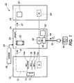
- FIG. 1 is block diagram illustrating a printer/copier in accordance with the invention.
- FIG. 2 illustrates method steps of the invention.
- the printer/copier 10 can include a feeder module 12 for feeding a substrate, including but not limited to paper, along a process route shown at 13.
- the substrate is fed from one or more trays, a plurality of which are shown at 14a-14c.
- the feeder 12 can include a fluffer 15 having a heater 16 for using heated air to separate the individual pieces of substrate in a known manner.
- the feeder module 12 can also include one or more tray heaters, one ofwhich is shown at 18, for reducing humidity in the vicinity of the substrate trays to improve substrate separation prior to feeding the substrate.
- the feeder feeds the separated substrates for printing and/or copying as shown by the dashed line and the arrow 19 at a feed rate that can determine, at least in part, the copy rate or the print rate.
- the printer/copier 10 can also include an electrophotographic processor module 20 for generating print and/or an image on the substrate in a suitable known manner.
- the electrophotographic processor 20 can include a photoreceptor 22 and fuser 24 disposed along the process route 13 for transferring the image to the substrate in a known manner.
- the printer/copier 20 can form/print the image on the substrate in any other known manner.
- the printer/copier 10 can also include a finisher module 26.
- the finisher receives the substrate with image from the electrophotographic processor 20 as shown by the arrow at 27.
- the finisher 26 can provide a wide range of substrate handling functions including but not limited to grouping, sorting, stapling, hole punching, etc.
- the printer/copier 10 can also include a substrate cooler 25 for cooling the substrate after the image is formed on it.
- the substrate cooler 25 can be located in any suitable location along the process route 13 in the printer/copier 10, such as for example, in the finisher module 26.
- the substrate cooler 25 can cool the substrate in any suitable known manner, including but not limited to, blowing air on the substrate.
- the printer/copier 10 can also include a scanner module 28 for providing an image in electronic form to the electrophotographic processor module 20 at 29 in any suitable known manner for transfer to the substrate in any suitable known manner.
- the printer/copier 10 also includes a power supply 30 for providing power to the printer/copier.
- the power supply 30 can include a plurality of separate power supplies, shown with dashed lines at 30', distributed to one or more of the printer/copier modules for providing power thereto.
- the power supply 30 can be any suitable known power supply for powering the printer/copier, including but not limited to a switching power supply.
- a line cord 32 connects the power supply 30 to a power source 34.
- the power source 34 can be any suitable known source for providing power to a printer/copier 10 such as, for example, a wall socket.
- the printer/copier power supply 30 draws line current from the power source 34 through the line cord 32 as shown by the arrow marked I L .
- the printer/copier power supply 30 typically acts as a constant power source attempting to provide an approximately constant amount of power to the printer/copier 10 while operating with a given functionality. Accordingly, when the line voltage V L at the power source 34 drops, the line current I L drawn through the line cord 32 increases maintaining the constant power condition. If the line voltage V L drops enough, the line current I L drawn through the line cord 32 will exceed a predetermined maximum value I max .
- I max may be established by the manufacturer of the printer/copier 10 or it may be set by a regulatory agency where the printer/copier is used. For example, I max for a single line cord 32 operating at a V L of 208 V, may be set at 24 A, although I max can be any other suitable current value and V L may be any other suitable voltage.
- the printer/copier 10 includes a current monitor 40 which monitors the line current I L .
- the current monitor 40 can be any suitable known device for determining the value of the line current I L and for signaling when the line current exceeds a predetermined threshold current I T .
- the printer/copier 10 also includes a functionality controller 42 communicating with the current monitor 40 at 44.
- the functionality controller 42 controls printer/copier functions by reducing the printer/copier functionality as described below to reduce the power used by the printer/copier 10 and thus reduce the line current I L as describe in further detail below.
- the invention includes a method of controlling the line current I L drawn by the printer/copier 10 through a line cord 32 connecting the printer to a power source 34.
- the method includes the current monitor 40 monitoring the line current I L at 52 and comparing it to the predetermined threshold value I T at 54.
- the threshold current value I T will be equal to or less than the maximum allowable current I max .
- the current monitor 40 determines that the line current I L exceeds the threshold value I T , the current monitor communicates this event to the functionality controller 42 via the communication link 44.
- the method also includes the functionality controller 42 reducing available printer/copier functionality at 56 when the line current exceeds the predetermined value I T to keep the line current I L from exceeding the predetermined maximum allowable line current I max .
- Reducing the printer/copier functionality can include altering printer/copier functions, and/or disabling, turning off, or in any other suitable way making printer/copier functions unavailable which were previously unaltered and/or available when the line current I L did not exceed the threshold value I T . Reducing printer/copier functionality in this manner reduces the power requirements of the printer/copier 10 therefore reducing the line current I L and preventing the line current I L from exceeding the maximum value I max .
- the functionality controller 42 can reduce the printer/copier functionality using software control, hardware control or any suitable combination thereof.
- the functionality controller 42 can reduce, disable, or otherwise make unavailable any single printer/copier function or any suitable combination of printer/copier functions in order to reduce the line current I L .
- Examples of reducing the printer/copier functionality can include, but are not limited to, reducing the thickness of substrate stock which the printer/copier can accommodate. This can be accomplished in any suitable known manner, including but not limited to, reducing the fusing temperature of the fuser in the electrophotographic processor.
- reducing the printer/copier functionality can include, but are not limited to, reducing the temperature of the flutter heater, disabling the fluffer heater, disabling the fluffer, reducing the temperature of the tray heater, disabling the tray heater, reducing the speed of one or more substrate cooling devices such as cooling fans, or disabling one or more of these substrate cooling devices.
- printer/copier functionality can include, but are not limited to, substrate handling functions performed by the finisher module, such as for example stapling and/or hole punching.
- reducing the printer/copier functionality can include, but are not limited to, reducing the copying and/or printing rate of the printer/copier 10. This can be accomplished in any suitable know manner, including but not limited to skipping pitches by reducing the number of images that are placed on the photo receptor 22, and/or reducing the process speed or feed rate of the substrate feeder 12, and/or increasing the gap between the substrates as they are fed to the electrophotographic processor 20.
Landscapes
- Engineering & Computer Science (AREA)
- Microelectronics & Electronic Packaging (AREA)
- Physics & Mathematics (AREA)
- General Physics & Mathematics (AREA)
- Control Or Security For Electrophotography (AREA)
- Accessory Devices And Overall Control Thereof (AREA)
Abstract
Description
- The present invention relates generally to printer/copier machines, and more particularly a system and method to prevent printer/copier line current from exceeding predetermined limits.
- Printer/copier machines can provide a wide range of functions for the user. As used herein, the term printer/copier applies to any printer, or copier, or multifunction machine which can print and/or copy, as well as perhaps, perform other functions such as scanning, etc. One subgroup of printer/copiers generate printed words or images on paper using the process of electrophotographic reproduction. Copiers reproduce an image of an original document to be copied placed onto the surface of a photoreceptor (or a photoconductive member ) either by illuminating the original document, which is projected upon the photoreceptor to produce a latent electrostatic image corresponding to the original document, or by placing the image onto the photoreceptor by electronic means. The latent electrostatic image is developed by a fuser fusing particles to produce a visible toner image that is transferred to the paper or other substrate. The unfused toner image may be fixed to the substrate by means of heat and pressure by pressing the substrate through the nip of a pair of rollers, at least one of which is heated.
- Printer/copiers must meet a number of design constraints. Customer demands and marketing forces impose criteria including the functions the machines should provide for a user.
- Other constraints are imposed by regulatory agencies such as limitations on the current Imax drawn by the device through the line cord. The current drawn from the power source through the line cord can vary and exceed these current limits resulting in an overcurrent condition. Typically, a printer/copier reacts to an overcurrent condition by shutting down, which can inconvenience the user. It is desirable to provide a more user friendly printer/copier response to conditions which can lead to an overcurrent situation.
- A system and method to prevent printer/copier line current from exceeding predetermined limits.
- In accordance with a first aspect of the invention a method of controlling line current IL drawn by a printer/copier through a line cord connecting the printer to a power source is provided. The method includes the monitoring line current IL and reducing available printer/copier functionality when the line current exceeds a predetermined value IT to keep the line current from exceeding predetermined maximum value Imax.
- In one embodiment the printer/copier includes a tray heater and the reducing step includes disabling the tray heater.
- In a further embodiment printer/copier includes a substrate cooler and the reducing step includes disabling the substrate cooler.
- In a further embodiment printer/copier includes a substrate cooler having a fan and the reducing step includes reducing the speed of the fan.
- In a further embodiment the reducing step includes reducing maximum copy rate.
- In a further embodiment the reducing step includes reducing the maximum printing rate.
- In a further embodiment the reducing step includes skipping pitches.
- In a further embodiment the reducing step includes increasing the gap between substrates traveling along a process route.
- In a further embodiment the reducing step includes reducing the available substrate handling functions.
- In accordance with a second aspect of the invention, a printer/copier is provided. The printer/copier includes a line cord connecting the printer to an AC power source for providing line current to the printer for printer operation. The printer/copier also includes a current monitor for monitoring line current drawn by the printer through the line cord. The printer/copier also includes a printer/copier functionality controller communicating with the current monitor for reducing printer/copier functionality when the line current exceeds a predetermined value IT to keep the line current from exceeding predetermined maximum value Imax.
- Other features, benefits and advantages of this invention will become apparent to those skilled in the art from the following detailed description of the preferred embodiments, when read in light of the accompanying drawings.
- The drawings are only for purposes of illustrating preferred embodiments and are not to be construed as limiting the invention. The invention may take form in various components and arrangements of components, and in various steps and arrangements of steps, preferred embodiments of which will be illustrated in the accompanying drawings wherein:
- FIG. 1 is block diagram illustrating a printer/copier in accordance with the invention; and
- FIG. 2 illustrates method steps of the invention.
- It is to be understood that the specific devices and processes illustrated in the attached drawings, and described in the following specification are simply exemplary embodiments of the inventive concepts defined in the appended claims. Hence, specific examples and characteristics relating to the embodiments disclosed herein are not to be considered as limiting, unless the claims expressly state otherwise.
- Referring now to Fig. 1, a printer/copier is shown generally at 10. The invention is applicable to any known printer/copier. The printer/
copier 10 can include afeeder module 12 for feeding a substrate, including but not limited to paper, along a process route shown at 13. The substrate is fed from one or more trays, a plurality of which are shown at 14a-14c. Thefeeder 12 can include afluffer 15 having aheater 16 for using heated air to separate the individual pieces of substrate in a known manner. Thefeeder module 12 can also include one or more tray heaters, one ofwhich is shown at 18, for reducing humidity in the vicinity of the substrate trays to improve substrate separation prior to feeding the substrate. The feeder feeds the separated substrates for printing and/or copying as shown by the dashed line and thearrow 19 at a feed rate that can determine, at least in part, the copy rate or the print rate. - The printer/
copier 10 can also include anelectrophotographic processor module 20 for generating print and/or an image on the substrate in a suitable known manner. Theelectrophotographic processor 20 can include aphotoreceptor 22 andfuser 24 disposed along theprocess route 13 for transferring the image to the substrate in a known manner. Alternatively, the printer/copier 20 can form/print the image on the substrate in any other known manner. - The printer/
copier 10 can also include afinisher module 26. The finisher receives the substrate with image from theelectrophotographic processor 20 as shown by the arrow at 27. Thefinisher 26 can provide a wide range of substrate handling functions including but not limited to grouping, sorting, stapling, hole punching, etc. The printer/copier 10 can also include asubstrate cooler 25 for cooling the substrate after the image is formed on it. Thesubstrate cooler 25 can be located in any suitable location along theprocess route 13 in the printer/copier 10, such as for example, in thefinisher module 26. Thesubstrate cooler 25 can cool the substrate in any suitable known manner, including but not limited to, blowing air on the substrate. - The printer/
copier 10 can also include ascanner module 28 for providing an image in electronic form to theelectrophotographic processor module 20 at 29 in any suitable known manner for transfer to the substrate in any suitable known manner. - The printer/
copier 10 also includes apower supply 30 for providing power to the printer/copier. Thepower supply 30 can include a plurality of separate power supplies, shown with dashed lines at 30', distributed to one or more of the printer/copier modules for providing power thereto. Thepower supply 30 can be any suitable known power supply for powering the printer/copier, including but not limited to a switching power supply. - A
line cord 32 connects thepower supply 30 to apower source 34. Thepower source 34 can be any suitable known source for providing power to a printer/copier 10 such as, for example, a wall socket. During operation, the printer/copier power supply 30 draws line current from thepower source 34 through theline cord 32 as shown by the arrow marked IL. - It has been found that the printer/
copier power supply 30 typically acts as a constant power source attempting to provide an approximately constant amount of power to the printer/copier 10 while operating with a given functionality. Accordingly, when the line voltage VL at thepower source 34 drops, the line current IL drawn through theline cord 32 increases maintaining the constant power condition. If the line voltage VL drops enough, the line current IL drawn through theline cord 32 will exceed a predetermined maximum value Imax. Imax may be established by the manufacturer of the printer/copier 10 or it may be set by a regulatory agency where the printer/copier is used. For example, Imax for asingle line cord 32 operating at a VL of 208 V, may be set at 24 A, although Imax can be any other suitable current value and VL may be any other suitable voltage. - The printer/
copier 10 includes acurrent monitor 40 which monitors the line current IL. Thecurrent monitor 40 can be any suitable known device for determining the value of the line current IL and for signaling when the line current exceeds a predetermined threshold current IT. The printer/copier 10 also includes afunctionality controller 42 communicating with thecurrent monitor 40 at 44. Thefunctionality controller 42 controls printer/copier functions by reducing the printer/copier functionality as described below to reduce the power used by the printer/copier 10 and thus reduce the line current IL as describe in further detail below. - As shown generally at 50 in Fig. 2, the invention includes a method of controlling the line current IL drawn by the printer/
copier 10 through aline cord 32 connecting the printer to apower source 34. The method includes thecurrent monitor 40 monitoring the line current IL at 52 and comparing it to the predetermined threshold value IT at 54. When the line voltage VL drops, such as occurs during a temporary low line voltage condition, the line current IL increases and can exceed the threshold value IT. The threshold current value IT will be equal to or less than the maximum allowable current Imax. When thecurrent monitor 40 determines that the line current IL exceeds the threshold value IT, the current monitor communicates this event to thefunctionality controller 42 via thecommunication link 44. The method also includes thefunctionality controller 42 reducing available printer/copier functionality at 56 when the line current exceeds the predetermined value IT to keep the line current IL from exceeding the predetermined maximum allowable line current Imax. - Reducing the printer/copier functionality can include altering printer/copier functions, and/or disabling, turning off, or in any other suitable way making printer/copier functions unavailable which were previously unaltered and/or available when the line current IL did not exceed the threshold value IT. Reducing printer/copier functionality in this manner reduces the power requirements of the printer/
copier 10 therefore reducing the line current IL and preventing the line current IL from exceeding the maximum value Imax. - The
functionality controller 42 can reduce the printer/copier functionality using software control, hardware control or any suitable combination thereof. Thefunctionality controller 42 can reduce, disable, or otherwise make unavailable any single printer/copier function or any suitable combination of printer/copier functions in order to reduce the line current IL. - Examples of reducing the printer/copier functionality can include, but are not limited to, reducing the thickness of substrate stock which the printer/copier can accommodate. This can be accomplished in any suitable known manner, including but not limited to, reducing the fusing temperature of the fuser in the electrophotographic processor.
- Other examples of reducing the printer/copier functionality can include, but are not limited to, reducing the temperature of the flutter heater, disabling the fluffer heater, disabling the fluffer, reducing the temperature of the tray heater, disabling the tray heater, reducing the speed of one or more substrate cooling devices such as cooling fans, or disabling one or more of these substrate cooling devices.
- Other examples of reducing the printer/copier functionality can include, but are not limited to, substrate handling functions performed by the finisher module, such as for example stapling and/or hole punching.
- Other examples of reducing the printer/copier functionality can include, but are not limited to, reducing the copying and/or printing rate of the printer/
copier 10. This can be accomplished in any suitable know manner, including but not limited to skipping pitches by reducing the number of images that are placed on thephoto receptor 22, and/or reducing the process speed or feed rate of thesubstrate feeder 12, and/or increasing the gap between the substrates as they are fed to theelectrophotographic processor 20.
Claims (10)
- A method of controlling line current ILdrawn by a printer/copier through a line cord connecting the printer to a power source comprising:monitoring line current IL drawn by the printer through the line cord; andreducing printer/copier functionality when the line current exceeds a predetermined value IT to keep the line current from exceeding predetermined maximum value Imax.
- The method defined in claim 1 further including comparing the line current IL with a predetermined value IT.
- The method defined in claim 1 wherein the reducing step includes reducing the thickness of the substrate stock which the printer/copier can accommodate.
- The method defined in claim 1 wherein the printer/copier includes a fuser and the reducing step includes reducing the fuser fusing temperature..
- The method defined in claim 1 wherein printer/copier includes a flutter having a heater and the reducing step includes reducing the flutter heater temperature.
- The method defined in claim 1 wherein printer/copier includes a fluffer having a heater and the reducing step includes disabling the fluffer heater.
- The method defined in claim 1 wherein printer/copier includes a fluffer having a heater and the reducing step includes disabling the fluffer.
- The method defined in claim 1 wherein printer/copier includes a tray heater and the reducing step includes reducing the temperature of the tray heater.
- A method of controlling line current drawn by a printer/copier through a line cord connecting the printer to a power source comprising:monitoring line current drawn by the printer through the line cord; andreducing available printer/copier functionality to keep the line current IL from exceeding a predetermined line current limit Imax.
- An printer/copier comprising:a line cord connecting the printer to an AC power source for providing line current to the printer for printer operation;a current monitor for monitoring line current drawn by the printer through the line cord; anda printer/copier functionality controller communicating with the current monitor for reducing printer/copier functionality when the line current exceeds a predetermined value IT to keep the line current from exceeding predetermined maximum value Imax.
Applications Claiming Priority (2)
| Application Number | Priority Date | Filing Date | Title |
|---|---|---|---|
| US10/355,751 US6768884B1 (en) | 2003-01-31 | 2003-01-31 | System and method of printer/copier active line current control |
| US355751 | 2003-01-31 |
Publications (2)
| Publication Number | Publication Date |
|---|---|
| EP1443367A1 true EP1443367A1 (en) | 2004-08-04 |
| EP1443367B1 EP1443367B1 (en) | 2008-07-09 |
Family
ID=32655587
Family Applications (1)
| Application Number | Title | Priority Date | Filing Date |
|---|---|---|---|
| EP04002187A Expired - Lifetime EP1443367B1 (en) | 2003-01-31 | 2004-01-30 | System and method of printer/copier active line current control |
Country Status (4)
| Country | Link |
|---|---|
| US (1) | US6768884B1 (en) |
| EP (1) | EP1443367B1 (en) |
| JP (1) | JP4532914B2 (en) |
| DE (1) | DE602004014828D1 (en) |
Cited By (1)
| Publication number | Priority date | Publication date | Assignee | Title |
|---|---|---|---|---|
| EP1878583A3 (en) * | 2006-07-14 | 2010-08-04 | Ricoh Company, Ltd. | Peripheral unit, image forming apparatus and image formation system using the same |
Families Citing this family (7)
| Publication number | Priority date | Publication date | Assignee | Title |
|---|---|---|---|---|
| US7277654B2 (en) * | 2005-06-24 | 2007-10-02 | Lexmark International, Inc. | Electrophotographic power supply configuration for supplying power to a fuser |
| US7500665B2 (en) * | 2005-09-28 | 2009-03-10 | Xerox Corporation | Method and device for improving pressure control in a sheet feeder |
| US7445205B2 (en) * | 2006-01-06 | 2008-11-04 | Xerox Corporation | Automatically variably heated airflow for separation of humid coated paper print media |
| JP2007293340A (en) * | 2006-04-21 | 2007-11-08 | Oce Technologies Bv | Variable speed printing device with mains overload prevention |
| SG136862A1 (en) * | 2006-04-21 | 2007-11-29 | Oce Tech Bv | Variable speed printing |
| US7832820B2 (en) * | 2006-10-31 | 2010-11-16 | Hewlett-Packard Development Company, L.P. | Regulating energy based on delivered energy |
| US11157053B2 (en) | 2017-05-01 | 2021-10-26 | Hewlett-Packard Development Company, L.P. | Auxiliary module power supply |
Citations (6)
| Publication number | Priority date | Publication date | Assignee | Title |
|---|---|---|---|---|
| EP0055315A1 (en) * | 1979-03-19 | 1982-07-07 | Cyborex Laboratories, Inc. | Improvements in or relating to energy management |
| NL8501097A (en) * | 1985-04-15 | 1986-04-01 | Oce Nederland Bv | POWER DISTRIBUTION IN A DEVICE. |
| US4996625A (en) * | 1988-09-02 | 1991-02-26 | Konica Corporation | Power source unit for image recording apparatus |
| JPH08188330A (en) * | 1995-01-06 | 1996-07-23 | Ricoh Co Ltd | Paper feeder |
| US6408149B1 (en) * | 1999-06-08 | 2002-06-18 | Canon Kabushiki Kaisha | Image processing apparatus, image reading apparatus, image formation apparatus, control method thereof, and storage medium |
| US20020076232A1 (en) * | 2000-12-15 | 2002-06-20 | Matsushita Graphic Communication Systems, Inc. | Image forming apparatus |
Family Cites Families (9)
| Publication number | Priority date | Publication date | Assignee | Title |
|---|---|---|---|---|
| KR970076112A (en) | 1996-05-21 | 1997-12-10 | 김광호 | Step-by-step power saving method for devices using electrophotographic development |
| US6353899B1 (en) | 1998-04-10 | 2002-03-05 | Xerox Corporation | Fault management system for a multifunctional printing machine |
| US6591073B1 (en) * | 1999-07-22 | 2003-07-08 | Hewlett-Packard Development Company, L.P. | Office printer with automatic input power sensing and variable throughput speed |
| US6375318B1 (en) * | 1999-09-21 | 2002-04-23 | Hewlett-Packard Company | Heated media input tray for an imaging device |
| JP2002040887A (en) * | 2000-07-19 | 2002-02-06 | Canon Inc | Image forming apparatus and control method thereof |
| JP2002072701A (en) * | 2000-08-28 | 2002-03-12 | Fuji Xerox Co Ltd | Image forming device |
| US6393233B1 (en) * | 2000-10-24 | 2002-05-21 | Hewlett-Packard Company | Printer fuser power management |
| JP2002127554A (en) * | 2000-10-27 | 2002-05-08 | Casio Electronics Co Ltd | Electronic equipment with power consumption limit control function |
| JP2002221878A (en) * | 2001-01-26 | 2002-08-09 | Konica Corp | Image forming device |
-
2003
- 2003-01-31 US US10/355,751 patent/US6768884B1/en not_active Expired - Lifetime
-
2004
- 2004-01-27 JP JP2004017840A patent/JP4532914B2/en not_active Expired - Fee Related
- 2004-01-30 DE DE602004014828T patent/DE602004014828D1/en not_active Expired - Lifetime
- 2004-01-30 EP EP04002187A patent/EP1443367B1/en not_active Expired - Lifetime
Patent Citations (6)
| Publication number | Priority date | Publication date | Assignee | Title |
|---|---|---|---|---|
| EP0055315A1 (en) * | 1979-03-19 | 1982-07-07 | Cyborex Laboratories, Inc. | Improvements in or relating to energy management |
| NL8501097A (en) * | 1985-04-15 | 1986-04-01 | Oce Nederland Bv | POWER DISTRIBUTION IN A DEVICE. |
| US4996625A (en) * | 1988-09-02 | 1991-02-26 | Konica Corporation | Power source unit for image recording apparatus |
| JPH08188330A (en) * | 1995-01-06 | 1996-07-23 | Ricoh Co Ltd | Paper feeder |
| US6408149B1 (en) * | 1999-06-08 | 2002-06-18 | Canon Kabushiki Kaisha | Image processing apparatus, image reading apparatus, image formation apparatus, control method thereof, and storage medium |
| US20020076232A1 (en) * | 2000-12-15 | 2002-06-20 | Matsushita Graphic Communication Systems, Inc. | Image forming apparatus |
Non-Patent Citations (2)
| Title |
|---|
| DATABASE WPI Section PQ Week 198619, Derwent World Patents Index; Class P84, AN 1986-123488, XP002279774, "Mains load current control system for photocopier - uses microprocessor to restrict max. and current monitoring detector current consumption at any time" * |
| PATENT ABSTRACTS OF JAPAN vol. 1996, no. 11 29 November 1996 (1996-11-29) * |
Cited By (1)
| Publication number | Priority date | Publication date | Assignee | Title |
|---|---|---|---|---|
| EP1878583A3 (en) * | 2006-07-14 | 2010-08-04 | Ricoh Company, Ltd. | Peripheral unit, image forming apparatus and image formation system using the same |
Also Published As
| Publication number | Publication date |
|---|---|
| US6768884B1 (en) | 2004-07-27 |
| JP2004287410A (en) | 2004-10-14 |
| EP1443367B1 (en) | 2008-07-09 |
| JP4532914B2 (en) | 2010-08-25 |
| DE602004014828D1 (en) | 2008-08-21 |
Similar Documents
| Publication | Publication Date | Title |
|---|---|---|
| US7020403B2 (en) | Image forming apparatus achieving reduction in power consumption | |
| US20080304850A1 (en) | Variable speed printing device with mains overload prevention | |
| US8180229B2 (en) | Apparatus and method of controlling interchange between component parts in the apparatus | |
| US20060239734A1 (en) | Image forming device | |
| US6768884B1 (en) | System and method of printer/copier active line current control | |
| US5915148A (en) | Network system for copiers | |
| US6473152B1 (en) | Image printing apparatus and table therefor | |
| JP2016206347A (en) | Image formation apparatus | |
| US10775720B2 (en) | Image forming apparatus having a cooling portion and a controller configured to operate the cooling portion in one mode of a plurality of modes | |
| US20240280932A1 (en) | Image forming apparatus | |
| US11704517B2 (en) | Image forming apparatus | |
| JP5298845B2 (en) | Image forming apparatus | |
| JP2022117337A (en) | image forming device | |
| JP6598893B2 (en) | Image forming apparatus | |
| US20150110511A1 (en) | Image Forming Apparatus Having Conveying Body and Transfer Units | |
| EP1847887A2 (en) | Variable speed printing device with mains overload prevention | |
| JP4007881B2 (en) | Image forming apparatus | |
| US7519319B2 (en) | Image forming device having a sheet delay transfer mode | |
| JP2021051255A (en) | Image forming apparatus | |
| US11117405B2 (en) | Image forming system | |
| JP5464139B2 (en) | Image forming apparatus | |
| JP2005258287A (en) | Image forming apparatus | |
| JP2009300779A (en) | Heat dissipating device and image forming apparatus using the same | |
| JP2006343525A (en) | Image forming apparatus | |
| JP2006284618A (en) | Dehumidification control apparatus for image forming apparatus |
Legal Events
| Date | Code | Title | Description |
|---|---|---|---|
| PUAI | Public reference made under article 153(3) epc to a published international application that has entered the european phase |
Free format text: ORIGINAL CODE: 0009012 |
|
| AK | Designated contracting states |
Kind code of ref document: A1 Designated state(s): AT BE BG CH CY CZ DE DK EE ES FI FR GB GR HU IE IT LI LU MC NL PT RO SE SI SK TR |
|
| AX | Request for extension of the european patent |
Extension state: AL LT LV MK |
|
| 17P | Request for examination filed |
Effective date: 20050204 |
|
| AKX | Designation fees paid |
Designated state(s): DE FR GB |
|
| RBV | Designated contracting states (corrected) |
Designated state(s): DE FR GB |
|
| GRAP | Despatch of communication of intention to grant a patent |
Free format text: ORIGINAL CODE: EPIDOSNIGR1 |
|
| GRAS | Grant fee paid |
Free format text: ORIGINAL CODE: EPIDOSNIGR3 |
|
| GRAA | (expected) grant |
Free format text: ORIGINAL CODE: 0009210 |
|
| AK | Designated contracting states |
Kind code of ref document: B1 Designated state(s): DE FR GB |
|
| REG | Reference to a national code |
Ref country code: GB Ref legal event code: FG4D |
|
| REF | Corresponds to: |
Ref document number: 602004014828 Country of ref document: DE Date of ref document: 20080821 Kind code of ref document: P |
|
| PLBE | No opposition filed within time limit |
Free format text: ORIGINAL CODE: 0009261 |
|
| STAA | Information on the status of an ep patent application or granted ep patent |
Free format text: STATUS: NO OPPOSITION FILED WITHIN TIME LIMIT |
|
| 26N | No opposition filed |
Effective date: 20090414 |
|
| REG | Reference to a national code |
Ref country code: FR Ref legal event code: PLFP Year of fee payment: 13 |
|
| REG | Reference to a national code |
Ref country code: FR Ref legal event code: PLFP Year of fee payment: 14 |
|
| PGFP | Annual fee paid to national office [announced via postgrant information from national office to epo] |
Ref country code: GB Payment date: 20161228 Year of fee payment: 14 |
|
| PGFP | Annual fee paid to national office [announced via postgrant information from national office to epo] |
Ref country code: FR Payment date: 20161221 Year of fee payment: 14 |
|
| PGFP | Annual fee paid to national office [announced via postgrant information from national office to epo] |
Ref country code: DE Payment date: 20161219 Year of fee payment: 14 |
|
| REG | Reference to a national code |
Ref country code: DE Ref legal event code: R119 Ref document number: 602004014828 Country of ref document: DE |
|
| GBPC | Gb: european patent ceased through non-payment of renewal fee |
Effective date: 20180130 |
|
| PG25 | Lapsed in a contracting state [announced via postgrant information from national office to epo] |
Ref country code: DE Free format text: LAPSE BECAUSE OF NON-PAYMENT OF DUE FEES Effective date: 20180801 Ref country code: FR Free format text: LAPSE BECAUSE OF NON-PAYMENT OF DUE FEES Effective date: 20180131 |
|
| REG | Reference to a national code |
Ref country code: FR Ref legal event code: ST Effective date: 20180928 |
|
| PG25 | Lapsed in a contracting state [announced via postgrant information from national office to epo] |
Ref country code: GB Free format text: LAPSE BECAUSE OF NON-PAYMENT OF DUE FEES Effective date: 20180130 |