EP1443204A2 - Hysteresis reduction in an exhaust gas recirculation valve - Google Patents
Hysteresis reduction in an exhaust gas recirculation valve Download PDFInfo
- Publication number
- EP1443204A2 EP1443204A2 EP04075234A EP04075234A EP1443204A2 EP 1443204 A2 EP1443204 A2 EP 1443204A2 EP 04075234 A EP04075234 A EP 04075234A EP 04075234 A EP04075234 A EP 04075234A EP 1443204 A2 EP1443204 A2 EP 1443204A2
- Authority
- EP
- European Patent Office
- Prior art keywords
- armature
- pole piece
- actuator
- bottom portion
- disposed
- Prior art date
- Legal status (The legal status is an assumption and is not a legal conclusion. Google has not performed a legal analysis and makes no representation as to the accuracy of the status listed.)
- Withdrawn
Links
Images


Classifications
-
- F—MECHANICAL ENGINEERING; LIGHTING; HEATING; WEAPONS; BLASTING
- F16—ENGINEERING ELEMENTS AND UNITS; GENERAL MEASURES FOR PRODUCING AND MAINTAINING EFFECTIVE FUNCTIONING OF MACHINES OR INSTALLATIONS; THERMAL INSULATION IN GENERAL
- F16K—VALVES; TAPS; COCKS; ACTUATING-FLOATS; DEVICES FOR VENTING OR AERATING
- F16K31/00—Actuating devices; Operating means; Releasing devices
- F16K31/02—Actuating devices; Operating means; Releasing devices electric; magnetic
- F16K31/06—Actuating devices; Operating means; Releasing devices electric; magnetic using a magnet, e.g. diaphragm valves, cutting off by means of a liquid
- F16K31/0686—Braking, pressure equilibration, shock absorbing
- F16K31/0696—Shock absorbing, e.g. using a dash-pot
-
- F—MECHANICAL ENGINEERING; LIGHTING; HEATING; WEAPONS; BLASTING
- F02—COMBUSTION ENGINES; HOT-GAS OR COMBUSTION-PRODUCT ENGINE PLANTS
- F02M—SUPPLYING COMBUSTION ENGINES IN GENERAL WITH COMBUSTIBLE MIXTURES OR CONSTITUENTS THEREOF
- F02M26/00—Engine-pertinent apparatus for adding exhaust gases to combustion-air, main fuel or fuel-air mixture, e.g. by exhaust gas recirculation [EGR] systems
- F02M26/52—Systems for actuating EGR valves
- F02M26/53—Systems for actuating EGR valves using electric actuators, e.g. solenoids
-
- F—MECHANICAL ENGINEERING; LIGHTING; HEATING; WEAPONS; BLASTING
- F02—COMBUSTION ENGINES; HOT-GAS OR COMBUSTION-PRODUCT ENGINE PLANTS
- F02M—SUPPLYING COMBUSTION ENGINES IN GENERAL WITH COMBUSTIBLE MIXTURES OR CONSTITUENTS THEREOF
- F02M26/00—Engine-pertinent apparatus for adding exhaust gases to combustion-air, main fuel or fuel-air mixture, e.g. by exhaust gas recirculation [EGR] systems
- F02M26/65—Constructional details of EGR valves
- F02M26/66—Lift valves, e.g. poppet valves
- F02M26/67—Pintles; Spindles; Springs; Bearings; Sealings; Connections to actuators
-
- F—MECHANICAL ENGINEERING; LIGHTING; HEATING; WEAPONS; BLASTING
- F02—COMBUSTION ENGINES; HOT-GAS OR COMBUSTION-PRODUCT ENGINE PLANTS
- F02M—SUPPLYING COMBUSTION ENGINES IN GENERAL WITH COMBUSTIBLE MIXTURES OR CONSTITUENTS THEREOF
- F02M26/00—Engine-pertinent apparatus for adding exhaust gases to combustion-air, main fuel or fuel-air mixture, e.g. by exhaust gas recirculation [EGR] systems
- F02M26/45—Sensors specially adapted for EGR systems
- F02M26/48—EGR valve position sensors
-
- F—MECHANICAL ENGINEERING; LIGHTING; HEATING; WEAPONS; BLASTING
- F02—COMBUSTION ENGINES; HOT-GAS OR COMBUSTION-PRODUCT ENGINE PLANTS
- F02M—SUPPLYING COMBUSTION ENGINES IN GENERAL WITH COMBUSTIBLE MIXTURES OR CONSTITUENTS THEREOF
- F02M26/00—Engine-pertinent apparatus for adding exhaust gases to combustion-air, main fuel or fuel-air mixture, e.g. by exhaust gas recirculation [EGR] systems
- F02M26/65—Constructional details of EGR valves
- F02M26/72—Housings
Definitions
- the present invention relates to exhaust gas recirculation valves for internal combustion engines; more particularly, to solenoid actuators for such valves; and most particularly, to resilient means for reducing hysteresis in the response of such actuators.
- Exhaust recirculation valves for internal combustion engines are well known.
- Such a valve typically includes a poppet-type valve mechanism actuated linearly by an electric solenoid in response to signals from an engine control module.
- the solenoid includes a central armature attached to the valve poppet.
- the armature is actuated by being drawn axially of primary and secondary electromagnetic pole pieces.
- the armature slides within, and is guided by, a non-ferromagnetic tube which also functions as a virtual "air gap" to enhance the axial force on the armature.
- the tube is pressed into the pole pieces and ideally remains stationary while the armature is reciprocated within.
- the axial space allotted for the guide tube must be slightly longer than the tube itself such that typically a small gap exists at one end or the other of the tube.
- the tube undesirably may be moved axially of the pole pieces due to friction with the moving armature during the duty cycle of the armature.
- the tube may be provided as a cup-shaped element having a blind end against which the armature instantaneously comes to rest before reversing its motion.
- This hard stop for the armature can result in undesirably rapid wear of the stop surface and of the armature itself.
- the impact force in an automotive solenoid may exceed 100 or more times the force of gravity.
- the guide and armature share very close tolerances and cannot be perfectly cylindrical, and because the closed end of the tube may be deformed from cylindrical ideality by the deep-drawing process for forming the tube, the armature typically tends to stick slightly as it approaches the blind end of the tube within the primary pole piece.
- a phenomenon known in the art as "magnetic latching" can cause the armature to stick, momentarily, against the pole piece. These occurrences can cause undesirable hysteresis in the duty cycle of the armature.
- a solenoid assembly in accordance with the invention includes a Hookian-like deformable element, for example, an undulated washer, disposed between the closed end of an armature guide tube and the primary or inward pole piece.
- the element is resilient and has a spring constant selected to 1) prevent axial motion of the guide tube due to frictional drag on the solenoid armature moving within the guide tube; 2) absorb and store a large percentage of the kinetic energy transferred by the armature impacting the end of the guide tube and reversing its motion; and 3) resiliently return a percentage of the stored energy to assist the armature in accelerating in the reverse direction.
- the element may take the form, for example, of a wavy-washer, a resilient mesh ring, or circular corrugation formed in the end of the tubular guide itself.
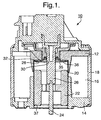
- a solenoid valve actuator 10 in accordance with the invention such as may be incorporated in, for example, an automotive exhaust gas recirculation valve, includes in known fashion a primary pole piece 12, a secondary pole piece 14, windings 16, a housing 18, a guide tube 20 disposed axially within the pole pieces 12,14, and an armature 22 slidingly disposed within guide tube 20. Also shown is a poppet valve stem 24 and an electronic position sensor shaft 26 axially moveable by stem 24 and armature 22 to sense the axial position thereof.
- Guide tube 20 is formed of a non-ferromagnetic material such as stainless steel, as by deep drawing in known fashion, and further includes a closed bottom portion 28 having a central opening 30 for receiving sensor shaft 26 therethrough.
- Bottom portion 28 preferably is formed having a raised corrugated rim 32, defining thereby an annular space 34 between bottom portion 28 and primary pole piece 12.
- armature 22 impacts bottom portion 28, the load being transferred to first pole piece 12 via rim 32 which, in the prior art, is urged against pole piece 12 by the impact of the armature.
- armature 22 is known to tend to become frictionally stuck in the guide tube against bottom portion 28 and to be hindered from returning linearly therefrom in the return stroke; and further, friction between tube 20 and armature 22 can cause tube 20 to be undesirably moved axially along with the armature during part of the armature cycle.
- an axially resilient element 36 which may take any of several forms.
- the primary purpose of element 36 is to provide shock absorption for the impact of armature 22 on tube bottom 28. Because bottom 28 is somewhat axially resilient itself as afforded by corrugated rim 32, element 36 allows a relatively soft impact of the armature against the bottom. Impact force reductions exceeding 75% have been observed. Because the intensity of impact is highly attenuated, there is reduced tendency for the armature to stick in the tube. Further, the energy absorbed in the resilient element and tube bottom is available to assist in spring-accelerating the armature in the reverse direction on the return stroke, this being a secondary purpose of element 36. Further, element 36 is sized such that tube 20 is urged axially against tube stop 37 and is prevented from being moved axially by friction with armature 22, this being a third purpose of element 36.
- element 36 comprises a wavy or undulated washer element; that is, a planar washer blank formed of spring steel or other suitable material which has been deformed into one or more axial-direction undulations angularly distributed about a center.
- the undulations are axially compressible to absorb the shock of armature impact.
- element 36 is a Belleville washer, which may be considered as having a half-wave undulation.
- a plurality of undulations is employed in an undulating washer element in accordance with the invention.
- the position of sensor shaft 26, expressed in voltage output of the sensor system is shown as a function of the electric duty cycle of the windings 16.
- the valve-opening stroke of the armature shown as curve 38
- the valve remains closed until the return spring force is overcome at about 25% of the duty cycle.
- the armature then moves nearly linearly until the valve is fully open at about 65% of the duty cycle (armature in contact with the tube bottom).
- hysteresis in decay of the electromagnetic field is shown in the fact that the valve-closing curve 40 is displaced to the left from the valve-opening curve 38.
- the armature is shown as experiencing difficulty in exiting the closed end of guide tube 20.
- the armature would begin to move at point 42, about 53% of the duty cycle as extrapolated from curve 40.
- such movement may be delayed until point 44 at about 40% of the duty cycle, at which time the valve jumps almost instantaneously from fully open to nearly half closed, making position control unacceptably imprecise.
- the armature begins to move at point 46, an improvement of about 70% from prior art point 44 to ideal point 42.
- a resilient element 36a may be an undulating washer having a plurality of layers.
- a resilient element 36b may be an annular structure formed from a resilient metal mesh.
- a resilient element 36c may be a radial leaf spring having a plurality of angularly spaced-apart radial leaves 39 formed as by punching in known fashion from bottom portion 28 of tubular guide 20.
- a resilient element 36d may be a captive retaining sleeve 60 disposed in an opening 30a in bottom 28a, having a first flange 62 extending radially over a portion of bottom 28a for stopping armature 22 (not shown in FIG. 6), and having a second flange 64 extending radially over a step 66 formed in pole piece 12 for retaining sleeve 60.
- the margin of opening 30a is rolled to form an annular resilient lip 68 which cooperates with sleeve 60 to absorb the shock of armature impact.
- embodiment 10' shows a resilient element 36' disposed within tube 20 against bottom portion 28. Although within the scope of the invention, this embodiment is not currently preferred. Such placement of element 36 meets the first two purposes described above but cannot prevent tube 20 from being moved axially by friction with, or the impact of, armature 22.
Landscapes
- Engineering & Computer Science (AREA)
- General Engineering & Computer Science (AREA)
- Mechanical Engineering (AREA)
- Chemical & Material Sciences (AREA)
- Combustion & Propulsion (AREA)
- Magnetically Actuated Valves (AREA)
Abstract
Description
Claims (10)
- In a solenoid actuator (10, 10') including a first magnetic pole piece (12), a second magnetic pole piece (14) spaced apart axially from said first pole piece, a tubular armature guide (20) disposed within said first and second pole pieces and having a bottom portion (28) spaced apart from an axial face (35) of said first pole piece, and an armature (22) slidably disposed within said tubular armature guide (20), the improvement comprising:a resilient element (36, 36a, 36b, 36c, 36d, 36') disposed between said axial face and said armature for absorbing the impact of said armature and for accelerating said armature away from said axial face.
- An actuator (10) in accordance with Claim 1 wherein said resilient element (36, 26a, 36b, 36c, 36d) is disposed between said bottom portion (28) and said axial face (35).
- An actuator (10') in accordance with Claim 1 wherein said resilient element (36') is disposed between said bottom portion (28) and said armature (22).
- An actuator (10) in accordance with Claim 1 wherein said resilient element is formed as a Belleville washer (36).
- An actuator (10) in accordance with Claim 1 wherein said resilient element (36, 36a) is formed as an undulating washer.
- An actuator (10) in accordance with Claim 5 wherein said undulating washer has a plurality of layers (36a).
- An actuator (10, 10') in accordance with Claim 1 wherein said resilient element (36b, 36') is formed as an annular structure from a resilient metal mesh.
- An actuator (10) in accordance with Claim 1 wherein said resilient element (36c) is formed as a plurality of angularly spaced-apart radial leaves (39) in said bottom portion.
- An actuator (10) in accordance with Claim 1 wherein said resilient element (36d) includes a captive sleeve (60) disposed in an opening in said bottom portion (28).
- An exhaust gas recirculation valve assembly for an internal combustion engine, the assembly comprising a solenoid actuator (10) includinga first magnetic pole piece (12),a second magnetic pole piece (16) spaced apart axially from said first pole piece,a tubular armature guide (20) disposed within said first and second pole pieces and having a bottom portion (28) spaced apart from an axial face (35) of said first pole piece,an armature (22) slidably disposed within said tubular armature guide (20), anda resilient element (36, 36a, 36b, 36c, 36d) disposed between said axial face (35) and said bottom portion (28) for absorbing the impact of said armature (22) against said bottom portion (28), for accelerating said armature away from said bottom portion.
Applications Claiming Priority (2)
| Application Number | Priority Date | Filing Date | Title |
|---|---|---|---|
| US10/355,965 US6708947B1 (en) | 2003-01-31 | 2003-01-31 | Hysteresis reduction in an exhaust gas recirculation valve |
| US355965 | 2003-01-31 |
Publications (2)
| Publication Number | Publication Date |
|---|---|
| EP1443204A2 true EP1443204A2 (en) | 2004-08-04 |
| EP1443204A3 EP1443204A3 (en) | 2010-08-11 |
Family
ID=31978156
Family Applications (1)
| Application Number | Title | Priority Date | Filing Date |
|---|---|---|---|
| EP04075234A Withdrawn EP1443204A3 (en) | 2003-01-31 | 2004-01-23 | Hysteresis reduction in an exhaust gas recirculation valve |
Country Status (2)
| Country | Link |
|---|---|
| US (1) | US6708947B1 (en) |
| EP (1) | EP1443204A3 (en) |
Families Citing this family (1)
| Publication number | Priority date | Publication date | Assignee | Title |
|---|---|---|---|---|
| DE502005002417D1 (en) * | 2005-07-26 | 2008-02-14 | Festo Ag & Co | Solenoid valve |
Family Cites Families (12)
| Publication number | Priority date | Publication date | Assignee | Title |
|---|---|---|---|---|
| US3707992A (en) * | 1970-11-09 | 1973-01-02 | Skinner Precision Ind Inc | Electromagnetic valve assembly |
| US5035360A (en) * | 1990-07-02 | 1991-07-30 | The University Of Toronto Innovations Foundation | Electrically actuated gaseous fuel timing and metering device |
| JP2997751B2 (en) * | 1990-10-31 | 2000-01-11 | ヤマハ発動機株式会社 | Solenoid valve device |
| US5328100A (en) * | 1992-09-22 | 1994-07-12 | Siemens Automotive L.P. | Modified armature for low noise injector |
| JP3479353B2 (en) * | 1994-10-17 | 2003-12-15 | 株式会社ケーヒン | Exhaust gas recirculation valve |
| US5626325A (en) * | 1995-09-14 | 1997-05-06 | Cummins Engine Company, Inc. | High pressure control valve for a fuel injection system |
| US5579741A (en) * | 1995-11-30 | 1996-12-03 | Siemens Electric Limited | Vapor purge valve having tapered bead armature seal |
| JP3518294B2 (en) * | 1997-08-08 | 2004-04-12 | トヨタ自動車株式会社 | Solenoid driven valve |
| US5947442A (en) * | 1997-09-10 | 1999-09-07 | Cummins Engine Company, Inc. | Solenoid actuated valve assembly |
| DE19754257A1 (en) * | 1997-12-06 | 1999-06-10 | Bosch Gmbh Robert | Solenoid valve for a liquid-controlled heating and / or cooling system |
| DE19831140B4 (en) * | 1998-07-11 | 2009-08-20 | Pierburg Gmbh | Exhaust gas recirculation valve |
| DE19905176A1 (en) * | 1999-02-09 | 2000-08-10 | Fev Motorentech Gmbh | Electromagnetic solenoid actuator with air-damper, locates damping cylinder at pole piece and piston just below armature, such that piston enters cylinder just before armature hits pole |
-
2003
- 2003-01-31 US US10/355,965 patent/US6708947B1/en not_active Expired - Fee Related
-
2004
- 2004-01-23 EP EP04075234A patent/EP1443204A3/en not_active Withdrawn
Also Published As
| Publication number | Publication date |
|---|---|
| US6708947B1 (en) | 2004-03-23 |
| EP1443204A3 (en) | 2010-08-11 |
Similar Documents
| Publication | Publication Date | Title |
|---|---|---|
| JP5982210B2 (en) | Electromagnetic fuel injection valve | |
| US5269269A (en) | Adjusting device for gas exchange valves | |
| US20080116024A1 (en) | Vibration damper with adjustable damping force | |
| CA2221848A1 (en) | Coaxial engine starter | |
| WO2016023757A1 (en) | Solenoid actuated fluid injection valve | |
| JP5494680B2 (en) | solenoid valve | |
| US5645019A (en) | Electromechanically actuated valve with soft landing and consistent seating force | |
| EP1805441B1 (en) | A solenoid actuated valve with a damping device | |
| US6637387B1 (en) | Variable valve actuating mechanism with magnetorheological fluid lost motion device | |
| US6708947B1 (en) | Hysteresis reduction in an exhaust gas recirculation valve | |
| US4479461A (en) | Coil spring damper for valve assemblies of internal combustion engines | |
| JP5890276B2 (en) | Electromagnetic solenoid | |
| WO2013086761A1 (en) | Shock absorber system and method | |
| CN106545682B (en) | Solenoid valve comprising armature with movable step | |
| US7481242B2 (en) | Solenoid-operated directional control valve | |
| CN106795842B (en) | Fuel injection valve | |
| KR20150046277A (en) | Injector for injecting fuel into an internal combustion engine | |
| US20050056712A1 (en) | Fuel injection valve | |
| EP2863042B1 (en) | Injection valve | |
| KR101736103B1 (en) | Linear actuator for vehicle transmission | |
| US20030107017A1 (en) | Electromagnetic valve actuator with soft-seating | |
| EP4649234A1 (en) | Fuel injector for direct injection of gaseous fuel | |
| WO1999023674A1 (en) | Cascading electromagnetic armature | |
| US20180195477A1 (en) | Valve for metering a fluid | |
| EP1666796B1 (en) | Gas safety valve with a damper for the movable armature |
Legal Events
| Date | Code | Title | Description |
|---|---|---|---|
| PUAI | Public reference made under article 153(3) epc to a published international application that has entered the european phase |
Free format text: ORIGINAL CODE: 0009012 |
|
| AK | Designated contracting states |
Kind code of ref document: A2 Designated state(s): AT BE BG CH CY CZ DE DK EE ES FI FR GB GR HU IE IT LI LU MC NL PT RO SE SI SK TR |
|
| AX | Request for extension of the european patent |
Extension state: AL LT LV MK |
|
| PUAL | Search report despatched |
Free format text: ORIGINAL CODE: 0009013 |
|
| AK | Designated contracting states |
Kind code of ref document: A3 Designated state(s): AT BE BG CH CY CZ DE DK EE ES FI FR GB GR HU IE IT LI LU MC NL PT RO SE SI SK TR |
|
| AX | Request for extension of the european patent |
Extension state: AL LT LV MK |
|
| AKY | No designation fees paid | ||
| REG | Reference to a national code |
Ref country code: DE Ref legal event code: R108 Effective date: 20110322 Ref country code: DE Ref legal event code: 8566 |
|
| STAA | Information on the status of an ep patent application or granted ep patent |
Free format text: STATUS: THE APPLICATION IS DEEMED TO BE WITHDRAWN |
|
| 18D | Application deemed to be withdrawn |
Effective date: 20110212 |