EP1443192A2 - Intake system - Google Patents
Intake system Download PDFInfo
- Publication number
- EP1443192A2 EP1443192A2 EP20040002232 EP04002232A EP1443192A2 EP 1443192 A2 EP1443192 A2 EP 1443192A2 EP 20040002232 EP20040002232 EP 20040002232 EP 04002232 A EP04002232 A EP 04002232A EP 1443192 A2 EP1443192 A2 EP 1443192A2
- Authority
- EP
- European Patent Office
- Prior art keywords
- intake
- passage
- peripheral wall
- intake pipe
- passage member
- Prior art date
- Legal status (The legal status is an assumption and is not a legal conclusion. Google has not performed a legal analysis and makes no representation as to the accuracy of the status listed.)
- Withdrawn
Links
- 238000003780 insertion Methods 0.000 claims abstract description 57
- 230000037431 insertion Effects 0.000 claims abstract description 57
- 230000002093 peripheral effect Effects 0.000 claims abstract description 46
- 238000006243 chemical reaction Methods 0.000 claims abstract description 13
- 238000006073 displacement reaction Methods 0.000 claims description 10
- 239000000463 material Substances 0.000 abstract description 6
- 241001272720 Medialuna californiensis Species 0.000 description 9
- 230000007423 decrease Effects 0.000 description 3
- 230000000694 effects Effects 0.000 description 2
- 239000007769 metal material Substances 0.000 description 2
- 239000011347 resin Substances 0.000 description 2
- 229920005989 resin Polymers 0.000 description 2
- 238000007789 sealing Methods 0.000 description 2
- 238000002485 combustion reaction Methods 0.000 description 1
- 230000006866 deterioration Effects 0.000 description 1
- 238000000034 method Methods 0.000 description 1
- 238000000465 moulding Methods 0.000 description 1
- 238000004826 seaming Methods 0.000 description 1
- 230000001629 suppression Effects 0.000 description 1
- 238000011144 upstream manufacturing Methods 0.000 description 1
Images



Classifications
-
- F—MECHANICAL ENGINEERING; LIGHTING; HEATING; WEAPONS; BLASTING
- F02—COMBUSTION ENGINES; HOT-GAS OR COMBUSTION-PRODUCT ENGINE PLANTS
- F02D—CONTROLLING COMBUSTION ENGINES
- F02D9/00—Controlling engines by throttling air or fuel-and-air induction conduits or exhaust conduits
- F02D9/08—Throttle valves specially adapted therefor; Arrangements of such valves in conduits
- F02D9/10—Throttle valves specially adapted therefor; Arrangements of such valves in conduits having pivotally-mounted flaps
-
- F—MECHANICAL ENGINEERING; LIGHTING; HEATING; WEAPONS; BLASTING
- F02—COMBUSTION ENGINES; HOT-GAS OR COMBUSTION-PRODUCT ENGINE PLANTS
- F02D—CONTROLLING COMBUSTION ENGINES
- F02D9/00—Controlling engines by throttling air or fuel-and-air induction conduits or exhaust conduits
- F02D9/08—Throttle valves specially adapted therefor; Arrangements of such valves in conduits
- F02D9/10—Throttle valves specially adapted therefor; Arrangements of such valves in conduits having pivotally-mounted flaps
- F02D9/107—Manufacturing or mounting details
-
- Y—GENERAL TAGGING OF NEW TECHNOLOGICAL DEVELOPMENTS; GENERAL TAGGING OF CROSS-SECTIONAL TECHNOLOGIES SPANNING OVER SEVERAL SECTIONS OF THE IPC; TECHNICAL SUBJECTS COVERED BY FORMER USPC CROSS-REFERENCE ART COLLECTIONS [XRACs] AND DIGESTS
- Y10—TECHNICAL SUBJECTS COVERED BY FORMER USPC
- Y10T—TECHNICAL SUBJECTS COVERED BY FORMER US CLASSIFICATION
- Y10T137/00—Fluid handling
- Y10T137/7504—Removable valve head and seat unit
-
- Y—GENERAL TAGGING OF NEW TECHNOLOGICAL DEVELOPMENTS; GENERAL TAGGING OF CROSS-SECTIONAL TECHNOLOGIES SPANNING OVER SEVERAL SECTIONS OF THE IPC; TECHNICAL SUBJECTS COVERED BY FORMER USPC CROSS-REFERENCE ART COLLECTIONS [XRACs] AND DIGESTS
- Y10—TECHNICAL SUBJECTS COVERED BY FORMER USPC
- Y10T—TECHNICAL SUBJECTS COVERED BY FORMER US CLASSIFICATION
- Y10T137/00—Fluid handling
- Y10T137/7504—Removable valve head and seat unit
- Y10T137/7668—Retained by bonnet or closure
Definitions
- the present invention relates to an intake system of an internal combustion engine, hereinafter referred to as an engine.
- a passage member for forming the intake passage along with an intake pipe is inserted into a peripheral wall of the intake pipe in the radial direction for assembly.
- the passage member is a throttle body which supports a throttle valve for opening and closing the intake passage.
- the passage member or throttle body is inserted through an insertion opening formed in the peripheral wall of the intake pipe, and the rear end of the throttle body in the direction of insertion is undetachably fixed to a part of the peripheral wall near the insertion opening. Furthermore, the front end of the throttle body in the direction of insertion is fastened to the peripheral wall by screws.
- the throttle body might vibrate in directions perpendicular to the axis of the direction of insertion due to collision of the intake air flowing through the intake passage, whereas the unstable front end of the throttle body is securely screwed to suppress the vibrations.
- the suppression of the vibrations of the throttle body prevents a seal member arranged at the seam between the peripheral wall of the intake pipe and the throttle body from wearing.
- An object of the present invention is to provide an intake system which is capable of easy component assembly and ensures the dimensional accuracy of the passage member. Besides, another object of the present invention is to provide an intake system that prevents the seal member arranged at the seam between the peripheral wall of the intake pipe and the passage member from wearing.
- a passage member is inserted into a peripheral wall of an intake pipe in the radial direction, and an elastic member is interposed between the peripheral wall and a front end of the passage member in the direction of insertion so as to be capable of giving the front end an elastic reaction force in a direction perpendicular to an axis of the direction of insertion.
- the passage member undergoing such an elastic reaction force from the elastic member with its front end, is suppressed in displacement in the direction perpendicular to the axis of the direction of insertion, and thus becomes less prone to vibrate. Consequently, a seal member arranged at a seam between the peripheral wall of the intake pipe and the passage member is prevented from wearing.
- the elastic member which causes no plastic deformation of the passage member, is interposed between the passage member and the intake pipe to suppress vibrations of the passage member, it is possible to ensure the dimensional accuracy of the passage member.
- the elastic member is integrally made of the same material as that of the seal member. This reduces the parts count and allows simultaneous, easy assembly of the elastic member and the seal member to predetermined positions.
- the peripheral wall of the intake pipe has an insertion opening for the passage member to be inserted through and a fitting part radially opposed to the insertion opening, while the fitting part and the front end of the passage member are fitted to each other with the elastic member interposed therebetween.
- the passage member can be inserted into the peripheral wall of the intake pipe through the insertion opening so that the front end of the passage member is fitted to the fitting part for easy assembly of the passage member to the intake pipe.
- the passage member is inserted into the intake pipe and fitted with the elastic member mounted on the front end of the passage member. The elastic member and the seal member can thus be easily, simultaneously assembled with the assembly of the passage member.
- the elastic member extends annularly around the axis of the direction of insertion between the fitting part and the front end of the passage member in a section perpendicular to the axis of the direction of insertion of the passage member. Consequently, the elastic member can give the front end of the passage member the elastic reaction force in any of directions perpendicular to the axis of the direction of insertion. This enhances the effect of suppressing vibrations of the passage member, and by extension, the effect of preventing the seal member from wearing.
- two seal members are arranged at seams between the passage member and the peripheral wall of the intake pipe so as to surround an inlet and an outlet of the intake passage formed in the passage member, respectively, and are further coupled via the elastic member. It is therefore possible to realize sealing facilities on both the inlet side and outlet side of the intake passage formed in the passage member while avoiding a deterioration in assemblability ascribable to the use of two seal members.
- the intake system has a supportingmeans for supporting the rear end of the passage member in the direction of insertion so as not to make a displacement in the direction opposite to the direction of insertion.
- the passage member can thus be prevented from coming off the intake pipe, whereby the relationship in relative position among the passage member, the intake pipe, and the elastic member interposed therebetween is maintained. Consequently, an intended elastic reaction force can be obtained from the elastic member with stability.
- thepassagemember isathrottlebodywhichsupports a throttle valve for opening and closing the intake passage.
- the throttle body desirably has a small tolerance on the clearance occurring between the wall surface that forms the intake passage and the outer periphery of the throttle valve. Since the dimensional accuracy of the passage member or throttle body is ensured, it is possible to reduce the tolerance on the foregoing clearance.
- Figs. 1 and 2 show an intake system of a vehicle engine according to the embodiment of the present invention.
- the intake system 10 comprises an intake pipe 20, a throttle body 40, and a gasket 60.
- the intake pipe 20 is of a metal material, for example, and formed in a generally cylindrical shape.
- An intake inlet 21 of the intake pipe 20 is connected to an intake outlet of an air cleaner (not shown).
- An intake outlet 22 of the intake pipe 20 is connected to an intake inlet of an intake manifold which is not shown.
- the intake pipe 20 has a peripheral wall 24 whose internal surface forms an intake passage 26.
- the intake passage 26 passes the intake air flowing into the intake inlet 21 from the air cleaner toward the intake outlet 22, guiding it to the intake manifold.
- the intake air guided to the intake manifold is supplied to the individual cylinders of the engine through the respective branch pipes of the intake manifold.
- the peripheral wall 24 of the intake pipe 20 is provided with an insertion opening 30, a guide groove 32, a fitting part 34, and a flange 36.
- the insertion opening 30 pierces through an axial center of the peripheral wall 24 in the radial direction.
- the guide groove 32 is made in the inside surface of the peripheral wall 24 and extends along, but not fully around, the same circumference that the insertion opening 30 falls on. Both circumferential ends of the guide groove 32 are connected to both circumferential sides of the insertion opening 30, respectively.
- the fitting part 34 is arranged in a position radially opposite to the insertion opening 30.
- the fitting part 34 has a closed-ended fitting hole 35 which opens in a bottom wall surface 37 of the guide groove 32.
- the fitting hole 35 is composed of a cylindrical hole part 35a on the opening side and a tapered hole part 35b on the bottom side.
- the cylindrical hole part 35a extends with a constant diameter.
- the tapered hole part 35b decreases in diameter toward the bottom.
- the flange 36 is formed in a flat shape so as to spread over a tangential plane of the external surface of the peripheral wall 24 around the insertion opening 30.
- the passage member or throttle body 40 is made of a metal material, for example, and has a main body 42, a fitting protrusion 44, and a flange 46.
- the main body 42 is formed in a so-called hog-backed shape, having a half-moon section.
- the main body 42 is inserted and fitted to the insertion opening 30 and the guide groove 32 in the peripheral wall 24 so that, in the half-moon section, the direction "a" from the center of the chord to the center of the arc coincides with the radial direction from the insertion opening 30 of the peripheral wall 24 to the fitting part 34.
- a direction "a” is the direction of insertion of the throttle body 40 into the peripheral wall 24.
- a bore piercing through the main body 42 in the direction perpendicular to the half-moon section forms an intake passage 48.
- the intake passage 48 is arranged so as to interrupt the intake passage 26, formed by the intake pipe 20, in the middle. These intake passages 48 and 26 constitute a single continuous intake passage.
- the intake passage 48 passes the intake air from the inlet 49 toward the outlet 50 along the intake flow in the intake passage 26 upstream and downstream thereacross.
- a side surface 51 of the main body 42 on the side of the inlet 49 and a side surface 52 of the same on the side of the outlet 50 are in contact with a side wall surface 38 and a side wall surface 39 of the guide groove 32, respectively.
- the area of contact between the side surface 51 and the side wall surface 38 and the area of contact between the side surface 52 and the side wall surface 39 are the seams between the main body 42 and the peripheral wall 24.
- the side surfaces 51 and 52 of the main body 42 are provided with mounting grooves 53 at their respective seaming areas.
- the mounting grooves 53 each consist of a seal groove part 53a and a connection groove part 53b.
- the seal groove part 53a extends in an annular shape which surrounds the inlet 49 or the outlet 50 of the intake passage 48.
- the connection groove part 53b extends linearly between a portion of the seal groove part 53a right next to the base of the fitting protrusion 44 and the base of the fitting protrusion 44.
- the main body 42 supports a throttle valve 54.
- a throttle shaft 55 of the throttle valve 54 extends on the axis "A" in the direction of insertion "a” (hereinafter, referred to simply as insertion direction axis A) across the intake passage 48, and is rotatably supported by the main body 42.
- a valve body 56 of the throttle valve 54 is formed in a disk shape and accommodated in the intake passage 48.
- the valve body 56 opens and closes the intake passage 48.
- the outer periphery of the valve body 56 and the bore internal surface of the main body 42 form a clearance, according to which the intake passages 48 and 26 are adjusted in intake flow rate.
- the fitting protrusion 44 protrudes from a center area of the arc in the half-moon section of the main body 42, in a direction opposite from the chord of the half-moon section. This fitting protrusion 44 corresponds to the front end of the throttle body 40 in the direction of insertion "a.”
- the fitting protrusion 44 is fitted to the fitting hole 35 with an elastic part 64 of the gasket 60 interposed between the fitting protrusion and the fitting hole 35, so as to be coaxial with the fitting hole 35.
- the fitting protrusion 44 is composed of a column base part 44a at a base portion and a tapered protrusion part 44b at an extremity.
- the column base part 44a extends with a constant diameter, and is accommodated in the cylindrical hole part 35a of the fitting hole 35.
- the tapered protrusion 44b decreases in diameter toward the extremity, and is accommodated in the tapered hole part 35b of the fitting hole 35.
- the flange 46 is arranged in the area of the chord in the half-moon section of the main body 42 and is formed in a flat shape perpendicular to the half-moon section. This flange 46 corresponds to the rear end of the throttle body 40 in the direction of insertion "a.”
- the flange 46 is put over the flange 36 of the intake pipe 20 on the external side of the peripheral wall 24 and is fastened to the flange 36 by a plurality of screw members 58.
- the gasket 60 is made of a resin material having elasticity, and has seal parts 62 for serving as seal members and an elastic part 64 for serving as an elastic member as shown in Figs. 1, 2, 4, and 5.
- the seal parts 62 and the elastic part 64 are formed by integral molding.
- the seal parts 62 are coupled with each other via the elastic part 64.
- the two seal parts 62 are fitted to the mounting grooves 53 in the side surfaces 51 and 52 of the main body 42, respectively.
- the seal parts 62 consist of a seal body 62a and a connection part 62b each.
- the seal body 62a is shaped like an O-ring, and is pressed into and held by the seal groove part 53a of the mounting groove 53.
- a surface of the seal body 62a opposite from the bottom wall surface of the seal groove part 53a is pressed against the side wall surface 38 or the side wall surface 39 of the guide groove 32.
- connection part 62b is formed linearly so as to extend from a point on the circumference of the seal body 62a, and is pressed into and held by the connection groove part 53b of the mounting groove 53.
- the elastic part 64 is shaped like a closed-ended cylinder.
- the elastic part 64 is interposed between the fitting hole 35 and the fitting protrusion 44 so that it extends annularly around the insertion direction axis A, between those components 35 and 44 in a section perpendicular to the insertion direction axis A.
- the elastic part 64 is composed of a cylindrical part 64a on the opening side and a tapered cylindrical part 64b on the bottom side.
- the cylindrical part 64a extends with a generally constant diameter, and fills the entire area between the cylindrical hole part 35a of the fitting hole 35 and the column base part 44a of the fitting protrusion 44 in the circumferential direction and axial direction.
- the cylindrical part 64a is sandwiched between the inside surfaceof the cylindrical hole part 35a and the outside surface of the column base part 44a both of which are in parallel with the insertion direction axis A.
- the opening rim of the cylindrical part 64a is connected with the connection parts 62b of the respective seal parts 62 at two radially-opposed positions.
- the tapered cylindrical part 64b decreases in diameter toward the bottom, and fills the entire area between the tapered hole part 35b of the fitting hole 35 and the tapered protrusion part 44b of the fitting protrusion 44 in the circumferential direction and axial direction. That is, the tapered cylindrical part 64b is sandwiched between the inside surface of the tapered hole part 35b and the outside surface of the tapered protrusion part 44b which are parallel with each other and have lines oblique to the insertion direction axis A.
- the gasket 60 is attached to the throttle body 40, and the throttle body 40, kept in the attached state, is inserted into the peripheral wall 24 of the intake pipe 20.
- the throttle body 40 and the gasket 60 can thus be simultaneously assembled with the intake pipe 20.
- the assembly of the gasket 60 consisting of the two seal parts 62, integrated with the elastic part 64 can reduce assembly errors, such as dropout and bite, as compared to the cases where the two seal parts 62 and the elastic part 64 are assembled as separate members.
- the elastic part 64 is sandwiched between the fitting hole 35 and the fitting protrusion 44 in any of the directions perpendicular to the insertion direction axis A.
- the elastic part 64 is elastically compressed by the fitting hole 35 and the fitting protrusion 44 at the front area in the direction of the relative displacement. Then, the compressed area of the cylindrical part 64a of the elastic part 64 exerts an elastic reaction force on the column base part 44a of the fitting protrusion 44 in the direction opposite to the direction of the relative displacement of the throttle body 40.
- the compressed area of the tapered cylindrical part 64b of the elastic part 64 can exert an elastic reaction force component on the tapered protrusion part 44b of the fitting protrusion 44 in the direction opposite to the direction of the relative displacement of the throttle body 40. Since the parts 44a and 44b of its fitting protrusion 44 receive the foregoing elastic reaction force and the foregoing elastic reaction force component from the parts 64a and 64b of the elastic part 64, the throttle body 40 is limited in displacement in the direction of the relative displacement.
- the elastic part 64 extending annularly around the insertion direction axis A is capable of applying the elastic reaction force in any of the directions perpendicular to the insertion direction axis A, vibrations of the throttle body 40 in any of the directions perpendicular to the insertion direction axis A are suppressed.
- the elastic part 64 elastically supports the fitting protrusion 44, suppressing vibrations of the throttle body 40.
- the seal parts 62 arranged at the seams between the main body 42 and the peripheral wall 24 are thus less prone to wear.
- the vibrations of the throttle body 40 are suppressed not by conventional screw members but by the elastic part 64, which causes no plastic deformation of the throttle body 40, it is possible to ensure the dimensional accuracy of the throttle body 40. This allows a smaller tolerance on the clearance formed between the outer periphery of the valve body 56 and the bore internal surface of the main body 42.
- the flange 46 of the throttle body 40 is fastened to the flange 36 of the intake pipe 20 by the screw members 58, whereby the throttle body 40 is supported so as not to make a displacement from the intake pipe 20 in the direction opposite to the direction of insertion "a.”
- the throttle body 40 is thus prevented from coming off the intake pipe 20, so that the fitting hole 35, the fitting protrusion 44, and the elastic part 64 between these components 35 and 44 are maintained in a generally constant relationship with regard to relative position.
- an intended elastic reaction force is obtained from the elastic part 64 with stability.
- the screw members 58 constitute the supporting means.
- the gasket 60 of the intake system 10 has the elastic part 64 aside from the seal parts 62.
- the seal parts 62 and the elastic part 64 can thus be configured separately so as to have a shape capable of sealing the seams between the main body 42 and the peripheral wall 24 and a shape capable of elastically supporting the fitting protrusion 44, respectively.
- the throttle body 40 for supporting the throttle valve 54 is adopted as the passage member.
- various types of members capable of being inserted into the peripheral wall of the intake pipe to form the intake passage along with the intake pipe may be adopted as the passage member of the present invention.
- the two seal parts 62 which surround the inlet 49 and the outlet 50 of the intake passage 48 formed in the throttle body 40, and the elastic part 64 are integrally formed of the same material (resin material).
- the seal parts 62 alone may be formed integrally with the elastic part 64.
- the peripheral wall 24 of the intake pipe 20 is provided with the fitting part 34 having the fitting hole 35, and the throttle body 40 is provided with the fitting protrusion 44 to be fitted to the fitting hole 35.
- the peripheral wall 24 of the intake pipe may be provided with a fitting part 34 having a fitting protrusion while the throttle body 40 is provided with a fitting hole to be fitted with the fitting protrusion.
- an elastic part 64 corresponding to the shape of the gap between the fitting protrusion of the fitting part 34 and the fitting hole of the throttle body 40 is arranged in the gap.
- the elastic part 64 is arranged so as to fill the entire area between the fitting protrusion 44 and the fitting hole 35 in the axial direction.
- the elastic part 64 may be arranged so as to fill part of the area between the fitting protrusion 44 and the fitting hole 35 in the axial direction.
- the elastic part 64- consists solely of a component corresponding to the cylindrical part 64a of the foregoing embodiment.
- the supporting means consists of the screw members 58.
- the supporting means may be composed of, for example, a clamp or the like that can give the peripheral wall 24 a force for sandwiching the main body 42 near the insertion opening 30 of the peripheral wall 24.
- the end of the main body 42 to be sandwiched near the insertion opening 30 of the peripheral wall 24 corresponds to the rear end of the throttle body 40 in the direction of insertion "a.”
- An intake system has an intake pipe (20), a passage member (40) which is inserted into a peripheral wall (24) of the intake pipe (20) in a radial direction to form an intake passage (48, 26) passing across a front end (44) and a rear end (46) thereof in a direction of insertion along with the intake pipe (20) a seal member (62) which is arranged at a seam between the peripheral wall (24) of the intake pipe (20) and the passage member (40) and seals the seam, and an elastic member (64) which is made of the same material as that of the seal member (62) integrally and is interposed between the peripheral wall (24) of the intake pipe (20) and the front end (44) of the passage member (40) so as to be capable of giving the front end (44) of the passage member (40) an elastic reaction force in a direction perpendicular to the axis of the direction of insertion.
Landscapes
- Engineering & Computer Science (AREA)
- Chemical & Material Sciences (AREA)
- Combustion & Propulsion (AREA)
- Mechanical Engineering (AREA)
- General Engineering & Computer Science (AREA)
- Control Of Throttle Valves Provided In The Intake System Or In The Exhaust System (AREA)
- Characterised By The Charging Evacuation (AREA)
Abstract
Description
- The present invention relates to an intake system of an internal combustion engine, hereinafter referred to as an engine.
- In conventionally known intake systems, a passage member for forming the intake passage along with an intake pipe is inserted into a peripheral wall of the intake pipe in the radial direction for assembly. Among examples of the passage member is a throttle body which supports a throttle valve for opening and closing the intake passage.
- In an intake system disclosed in Japanese Patent Laid-Open Publication No. Hei 10-103089 (1998), the passage member or throttle body is inserted through an insertion opening formed in the peripheral wall of the intake pipe, and the rear end of the throttle body in the direction of insertion is undetachably fixed to a part of the peripheral wall near the insertion opening. Furthermore, the front end of the throttle body in the direction of insertion is fastened to the peripheral wall by screws. The throttle body might vibrate in directions perpendicular to the axis of the direction of insertion due to collision of the intake air flowing through the intake passage, whereas the unstable front end of the throttle body is securely screwed to suppress the vibrations. The suppression of the vibrations of the throttle body prevents a seal member arranged at the seam between the peripheral wall of the intake pipe and the throttle body from wearing.
- When the front end of the throttle body in the direction of insertion is fastened to the peripheral wall of the intake pipe by the screws, however the screwing of the screw members causes a plastic deformation of the throttle body with a drop in the dimensional accuracy of the bore and the like. In addition, the screw fastening increases the parts count and complicates the assembling operation with an inevitable increase in cost.
- An object of the present invention is to provide an intake system which is capable of easy component assembly and ensures the dimensional accuracy of the passage member. Besides, another object of the present invention is to provide an intake system that prevents the seal member arranged at the seam between the peripheral wall of the intake pipe and the passage member from wearing.
- According to an intake system according to a first aspect of the present invention, a passage member is inserted into a peripheral wall of an intake pipe in the radial direction, and an elastic member is interposed between the peripheral wall and a front end of the passage member in the direction of insertion so as to be capable of giving the front end an elastic reaction force in a direction perpendicular to an axis of the direction of insertion. The passage member, undergoing such an elastic reaction force from the elastic member with its front end, is suppressed in displacement in the direction perpendicular to the axis of the direction of insertion, and thus becomes less prone to vibrate. Consequently, a seal member arranged at a seam between the peripheral wall of the intake pipe and the passage member is prevented from wearing. Moreover, since the elastic member, which causes no plastic deformation of the passage member, is interposed between the passage member and the intake pipe to suppress vibrations of the passage member, it is possible to ensure the dimensional accuracy of the passage member. In addition, the elastic member is integrally made of the same material as that of the seal member. This reduces the parts count and allows simultaneous, easy assembly of the elastic member and the seal member to predetermined positions.
- According to the intake system according to a second aspect of the present invention, the peripheral wall of the intake pipe has an insertion opening for the passage member to be inserted through and a fitting part radially opposed to the insertion opening, while the fitting part and the front end of the passage member are fitted to each other with the elastic member interposed therebetween. According to this configuration, the passage member can be inserted into the peripheral wall of the intake pipe through the insertion opening so that the front end of the passage member is fitted to the fitting part for easy assembly of the passage member to the intake pipe. Moreover, the passage member is inserted into the intake pipe and fitted with the elastic member mounted on the front end of the passage member. The elastic member and the seal member can thus be easily, simultaneously assembled with the assembly of the passage member.
- According to the intake system according to a third aspect of the present invention, the elastic member extends annularly around the axis of the direction of insertion between the fitting part and the front end of the passage member in a section perpendicular to the axis of the direction of insertion of the passage member. Consequently, the elastic member can give the front end of the passage member the elastic reaction force in any of directions perpendicular to the axis of the direction of insertion. This enhances the effect of suppressing vibrations of the passage member, and by extension, the effect of preventing the seal member from wearing.
- According to the intake system according to a fourth aspect of the present invention, two seal members are arranged at seams between the passage member and the peripheral wall of the intake pipe so as to surround an inlet and an outlet of the intake passage formed in the passage member, respectively, and are further coupled via the elastic member. It is therefore possible to realize sealing facilities on both the inlet side and outlet side of the intake passage formed in the passage member while avoiding a deterioration in assemblability ascribable to the use of two seal members.
- The intake system according to a fifth aspect of the present invention has a supportingmeans for supporting the rear end of the passage member in the direction of insertion so as not to make a displacement in the direction opposite to the direction of insertion. The passage member can thus be prevented from coming off the intake pipe, whereby the relationship in relative position among the passage member, the intake pipe, and the elastic member interposed therebetween is maintained. Consequently, an intended elastic reaction force can be obtained from the elastic member with stability.
- According to the intake system according to a sixth aspect of the present invention, thepassagememberisathrottlebodywhichsupports a throttle valve for opening and closing the intake passage. The throttle body desirably has a small tolerance on the clearance occurring between the wall surface that forms the intake passage and the outer periphery of the throttle valve. Since the dimensional accuracy of the passage member or throttle body is ensured, it is possible to reduce the tolerance on the foregoing clearance.
- Further areas of applicability of the present invention will become apparent from the detailed description provided hereinafter. It should be understood that the detailed description and specific examples, while indicating the preferred embodiment of the invention, are intended for purposes of illustration only and are not intended to limit the scope of the invention.
- The present invention will become more fully understood from the detailed description and the accompanying drawings, wherein:
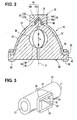
- Fig. 1 is a cross-sectional view showing an intake system according to an embodiment of the present invention;
- Fig. 2 is a cross-sectional view of Fig. 1 taken along the line II-II;
- Fig. 3 is an external perspective view of the intake pipe shown in Fig. 1;
- Fig. 4 is an external perspective view of the throttle body shown in Fig. 1;
- Fig. 5 is an external perspective view of the gasket shown in Fig. 1; and
- Fig. 6 is a cross-sectional view showing a modified example of the intake system according to the embodiment of the present invention.
-
- Hereinafter, an embodiment showing the mode of carrying out the present invention will be described with reference to the drawings.
- Figs. 1 and 2 show an intake system of a vehicle engine according to the embodiment of the present invention. The
intake system 10 comprises anintake pipe 20, athrottle body 40, and agasket 60. As shown in Figs. 1 to 3, theintake pipe 20 is of a metal material, for example, and formed in a generally cylindrical shape. Anintake inlet 21 of theintake pipe 20 is connected to an intake outlet of an air cleaner (not shown). Anintake outlet 22 of theintake pipe 20 is connected to an intake inlet of an intake manifold which is not shown. Theintake pipe 20 has aperipheral wall 24 whose internal surface forms anintake passage 26. Theintake passage 26 passes the intake air flowing into theintake inlet 21 from the air cleaner toward theintake outlet 22, guiding it to the intake manifold. Incidentally, the intake air guided to the intake manifold is supplied to the individual cylinders of the engine through the respective branch pipes of the intake manifold. - The
peripheral wall 24 of theintake pipe 20 is provided with an insertion opening 30, aguide groove 32, afitting part 34, and aflange 36. The insertion opening 30 pierces through an axial center of theperipheral wall 24 in the radial direction. Theguide groove 32 is made in the inside surface of theperipheral wall 24 and extends along, but not fully around, the same circumference that the insertion opening 30 falls on. Both circumferential ends of theguide groove 32 are connected to both circumferential sides of the insertion opening 30, respectively. Thefitting part 34 is arranged in a position radially opposite to the insertion opening 30. Thefitting part 34 has a closed-ended fitting hole 35 which opens in abottom wall surface 37 of theguide groove 32. Thefitting hole 35 is composed of acylindrical hole part 35a on the opening side and atapered hole part 35b on the bottom side. Thecylindrical hole part 35a extends with a constant diameter. Thetapered hole part 35b decreases in diameter toward the bottom. Theflange 36 is formed in a flat shape so as to spread over a tangential plane of the external surface of theperipheral wall 24 around the insertion opening 30. - As shown in Figs. 1, 2, and 4, the passage member or
throttle body 40 is made of a metal material, for example, and has amain body 42, afitting protrusion 44, and aflange 46. Themain body 42 is formed in a so-called hog-backed shape, having a half-moon section. Themain body 42 is inserted and fitted to theinsertion opening 30 and theguide groove 32 in theperipheral wall 24 so that, in the half-moon section, the direction "a" from the center of the chord to the center of the arc coincides with the radial direction from theinsertion opening 30 of theperipheral wall 24 to thefitting part 34. Such a direction "a" is the direction of insertion of thethrottle body 40 into theperipheral wall 24. - A bore piercing through the
main body 42 in the direction perpendicular to the half-moon section forms anintake passage 48. Theintake passage 48 is arranged so as to interrupt theintake passage 26, formed by theintake pipe 20, in the middle. Theseintake passages intake passage 48 passes the intake air from theinlet 49 toward theoutlet 50 along the intake flow in theintake passage 26 upstream and downstream thereacross. Aside surface 51 of themain body 42 on the side of theinlet 49 and aside surface 52 of the same on the side of theoutlet 50 are in contact with aside wall surface 38 and aside wall surface 39 of theguide groove 32, respectively. The area of contact between theside surface 51 and theside wall surface 38 and the area of contact between theside surface 52 and theside wall surface 39 are the seams between themain body 42 and theperipheral wall 24. The side surfaces 51 and 52 of themain body 42 are provided with mountinggrooves 53 at their respective seaming areas. The mountinggrooves 53 each consist of aseal groove part 53a and aconnection groove part 53b. Theseal groove part 53a extends in an annular shape which surrounds theinlet 49 or theoutlet 50 of theintake passage 48. Theconnection groove part 53b extends linearly between a portion of theseal groove part 53a right next to the base of thefitting protrusion 44 and the base of thefitting protrusion 44. - The
main body 42 supports athrottle valve 54. Athrottle shaft 55 of thethrottle valve 54 extends on the axis "A" in the direction of insertion "a" (hereinafter, referred to simply as insertion direction axis A) across theintake passage 48, and is rotatably supported by themain body 42. Avalve body 56 of thethrottle valve 54 is formed in a disk shape and accommodated in theintake passage 48. When thethrottle shaft 55 is rotated by a driving unit (not shown), thevalve body 56 opens and closes theintake passage 48. Here, the outer periphery of thevalve body 56 and the bore internal surface of themain body 42 form a clearance, according to which theintake passages - The
fitting protrusion 44 protrudes from a center area of the arc in the half-moon section of themain body 42, in a direction opposite from the chord of the half-moon section. Thisfitting protrusion 44 corresponds to the front end of thethrottle body 40 in the direction of insertion "a." Thefitting protrusion 44 is fitted to thefitting hole 35 with anelastic part 64 of thegasket 60 interposed between the fitting protrusion and thefitting hole 35, so as to be coaxial with thefitting hole 35. Thefitting protrusion 44 is composed of acolumn base part 44a at a base portion and atapered protrusion part 44b at an extremity. Thecolumn base part 44a extends with a constant diameter, and is accommodated in thecylindrical hole part 35a of thefitting hole 35. The taperedprotrusion 44b decreases in diameter toward the extremity, and is accommodated in the taperedhole part 35b of thefitting hole 35. - The
flange 46 is arranged in the area of the chord in the half-moon section of themain body 42 and is formed in a flat shape perpendicular to the half-moon section. Thisflange 46 corresponds to the rear end of thethrottle body 40 in the direction of insertion "a." Theflange 46 is put over theflange 36 of theintake pipe 20 on the external side of theperipheral wall 24 and is fastened to theflange 36 by a plurality ofscrew members 58. Thegasket 60 is made of a resin material having elasticity, and hasseal parts 62 for serving as seal members and anelastic part 64 for serving as an elastic member as shown in Figs. 1, 2, 4, and 5. Theseal parts 62 and theelastic part 64 are formed by integral molding. - There are two
seal parts 62, which are coupled with each other via theelastic part 64. The twoseal parts 62 are fitted to the mountinggrooves 53 in the side surfaces 51 and 52 of themain body 42, respectively. Theseal parts 62 consist of aseal body 62a and aconnection part 62b each. Theseal body 62a is shaped like an O-ring, and is pressed into and held by theseal groove part 53a of the mountinggroove 53. A surface of theseal body 62a opposite from the bottom wall surface of theseal groove part 53a is pressed against theside wall surface 38 or theside wall surface 39 of theguide groove 32. consequently, the above-mentioned seams between themain body 42 and theperipheral wall 24 are sealed in an air-tight fashion both on the side of theinlet 49 and on the side of theoutlet 50 of theintake passage 48. Theconnection part 62b is formed linearly so as to extend from a point on the circumference of theseal body 62a, and is pressed into and held by theconnection groove part 53b of the mountinggroove 53. - The
elastic part 64 is shaped like a closed-ended cylinder. Theelastic part 64 is interposed between thefitting hole 35 and thefitting protrusion 44 so that it extends annularly around the insertion direction axis A, between thosecomponents elastic part 64 is composed of acylindrical part 64a on the opening side and a taperedcylindrical part 64b on the bottom side. Thecylindrical part 64a extends with a generally constant diameter, and fills the entire area between thecylindrical hole part 35a of thefitting hole 35 and thecolumn base part 44a of thefitting protrusion 44 in the circumferential direction and axial direction. That is, thecylindrical part 64a is sandwiched between the inside surfaceof thecylindrical hole part 35a and the outside surface of thecolumn base part 44a both of which are in parallel with the insertion direction axis A. The opening rim of thecylindrical part 64a is connected with theconnection parts 62b of therespective seal parts 62 at two radially-opposed positions. The taperedcylindrical part 64b decreases in diameter toward the bottom, and fills the entire area between thetapered hole part 35b of thefitting hole 35 and the taperedprotrusion part 44b of thefitting protrusion 44 in the circumferential direction and axial direction. That is, the taperedcylindrical part 64b is sandwiched between the inside surface of the taperedhole part 35b and the outside surface of the taperedprotrusion part 44b which are parallel with each other and have lines oblique to the insertion direction axis A. - Next, description will be given of the method of mounting the
throttle body 40 and thegasket 60 on theintake pipe 20 to assemble theintake system 10. - (1) The
gasket 60 is attached to thethrottle body 40 which is assembled with thethrottle valve 54, the driving unit, and the like in advance. Specifically, thefitting protrusion 44 is initially pressed into theelastic part 64. Then, theseal parts 62 are pressed into the respective mountinggrooves 53. - (2) The
throttle body 40 is inserted into theperipheral wall 24 of theintake pipe 20 in the direction of insertion "a." Specifically, thethrottle body 40 is initially inserted through theinsertion opening 30 of theperipheral wall 24 with thefitting protrusion 44 first. Then, thefitting protrusion 44 is fitted into thefitting hole 35 of theperipheral wall 24 while themain body 42 is guided by the side wall surfaces 38 and 39 of theguide groove 32. Consequently, the outer periphery of themain body 42 which forms the arc of the half-moon section and the end of themain body 42 which forms the chord of the half-moon section are inserted and fitted to theguide groove 32 and theinsertion opening 30, respectively. At the same time, theparts gasket 60 are set into their respective predetermined positions. - (3) The
flange 36 of theintake pipe 20 and theflange 46 of thethrottle body 40 are fastened at a plurality of points by thescrew members 58. -
- As described above, the
gasket 60 is attached to thethrottle body 40, and thethrottle body 40, kept in the attached state, is inserted into theperipheral wall 24 of theintake pipe 20. Thethrottle body 40 and thegasket 60 can thus be simultaneously assembled with theintake pipe 20. In addition, the assembly of thegasket 60 consisting of the twoseal parts 62, integrated with theelastic part 64, can reduce assembly errors, such as dropout and bite, as compared to the cases where the twoseal parts 62 and theelastic part 64 are assembled as separate members. - In the
intake system 10 described above, theelastic part 64 is sandwiched between thefitting hole 35 and thefitting protrusion 44 in any of the directions perpendicular to the insertion direction axis A. Thus, when the intake air flowing through theintake passages throttle body 40 relative to theintake pipe 20 in a direction perpendicular to the insertion direction axis A, such as the axial direction of theintake pipe 20, theelastic part 64 is elastically compressed by thefitting hole 35 and thefitting protrusion 44 at the front area in the direction of the relative displacement. Then, the compressed area of thecylindrical part 64a of theelastic part 64 exerts an elastic reaction force on thecolumn base part 44a of thefitting protrusion 44 in the direction opposite to the direction of the relative displacement of thethrottle body 40. Moreover, the compressed area of the taperedcylindrical part 64b of theelastic part 64 can exert an elastic reaction force component on the taperedprotrusion part 44b of thefitting protrusion 44 in the direction opposite to the direction of the relative displacement of thethrottle body 40. Since theparts fitting protrusion 44 receive the foregoing elastic reaction force and the foregoing elastic reaction force component from theparts elastic part 64, thethrottle body 40 is limited in displacement in the direction of the relative displacement. Since theelastic part 64 extending annularly around the insertion direction axis A is capable of applying the elastic reaction force in any of the directions perpendicular to the insertion direction axis A, vibrations of thethrottle body 40 in any of the directions perpendicular to the insertion direction axis A are suppressed. - Consequently, in the
intake system 10, theelastic part 64 elastically supports thefitting protrusion 44, suppressing vibrations of thethrottle body 40. Theseal parts 62 arranged at the seams between themain body 42 and theperipheral wall 24 are thus less prone to wear. Besides, since the vibrations of thethrottle body 40 are suppressed not by conventional screw members but by theelastic part 64, which causes no plastic deformation of thethrottle body 40, it is possible to ensure the dimensional accuracy of thethrottle body 40. This allows a smaller tolerance on the clearance formed between the outer periphery of thevalve body 56 and the bore internal surface of themain body 42. - Furthermore, in the
intake system 10, theflange 46 of thethrottle body 40 is fastened to theflange 36 of theintake pipe 20 by thescrew members 58, whereby thethrottle body 40 is supported so as not to make a displacement from theintake pipe 20 in the direction opposite to the direction of insertion "a." Thethrottle body 40 is thus prevented from coming off theintake pipe 20, so that thefitting hole 35, thefitting protrusion 44, and theelastic part 64 between thesecomponents elastic part 64 with stability. - In the present embodiment, the
screw members 58 constitute the supporting means. Additionally, thegasket 60 of theintake system 10 has theelastic part 64 aside from theseal parts 62. Theseal parts 62 and theelastic part 64 can thus be configured separately so as to have a shape capable of sealing the seams between themain body 42 and theperipheral wall 24 and a shape capable of elastically supporting thefitting protrusion 44, respectively. - Incidentally, in the foregoing embodiment, the
throttle body 40 for supporting thethrottle valve 54 is adopted as the passage member. Nevertheless, various types of members capable of being inserted into the peripheral wall of the intake pipe to form the intake passage along with the intake pipe may be adopted as the passage member of the present invention. - Additionally, in the foregoing embodiment, the two
seal parts 62, which surround theinlet 49 and theoutlet 50 of theintake passage 48 formed in thethrottle body 40, and theelastic part 64 are integrally formed of the same material (resin material). However, either one of theseal parts 62 alone may be formed integrally with theelastic part 64. - Moreover, in the foregoing embodiment, the
peripheral wall 24 of theintake pipe 20 is provided with thefitting part 34 having thefitting hole 35, and thethrottle body 40 is provided with thefitting protrusion 44 to be fitted to thefitting hole 35. Conversely, theperipheral wall 24 of the intake pipe may be provided with afitting part 34 having a fitting protrusion while thethrottle body 40 is provided with a fitting hole to be fitted with the fitting protrusion. Even in this case, anelastic part 64 corresponding to the shape of the gap between the fitting protrusion of thefitting part 34 and the fitting hole of thethrottle body 40 is arranged in the gap. - Furthermore, in the foregoing embodiment, the
elastic part 64 is arranged so as to fill the entire area between thefitting protrusion 44 and thefitting hole 35 in the axial direction. Nevertheless, as in a modified example shown in Fig. 6, theelastic part 64 may be arranged so as to fill part of the area between thefitting protrusion 44 and thefitting hole 35 in the axial direction. incidentally, in the modified example shown in Fig. 6, the elastic part 64-consists solely of a component corresponding to thecylindrical part 64a of the foregoing embodiment. - Additionally, in the foregoing embodiment, the supporting means consists of the
screw members 58. Nevertheless, the supporting means may be composed of, for example, a clamp or the like that can give the peripheral wall 24 a force for sandwiching themain body 42 near theinsertion opening 30 of theperipheral wall 24. In this case, the end of themain body 42 to be sandwiched near theinsertion opening 30 of theperipheral wall 24 corresponds to the rear end of thethrottle body 40 in the direction of insertion "a." - The description of the invention is merely exemplary in nature and, thus, variations that do not depart from the gist of the invention are intended to be within the scope of the invention. Such variations are not to be regarded as a departure from the spirit and scope of the invention.
- An intake system has an intake pipe (20), a passage member (40) which is inserted into a peripheral wall (24) of the intake pipe (20) in a radial direction to form an intake passage (48, 26) passing across a front end (44) and a rear end (46) thereof in a direction of insertion along with the intake pipe (20) a seal member (62) which is arranged at a seam between the peripheral wall (24) of the intake pipe (20) and the passage member (40) and seals the seam, and an elastic member (64) which is made of the same material as that of the seal member (62) integrally and is interposed between the peripheral wall (24) of the intake pipe (20) and the front end (44) of the passage member (40) so as to be capable of giving the front end (44) of the passage member (40) an elastic reaction force in a direction perpendicular to the axis of the direction of insertion.
Claims (6)
- An intake system (10) comprising:an intake pipe (20);a passage member (40) which is inserted into a peripheral wall (24) of said intake pipe (20) in a radial direction to form an intake passage (48) passing across a front end and a rear end thereof in a direction of insertion along with said intake pipe (20);a seal member (62) which is arranged at a seam between said peripheral wall (24) and said passage member (40) and seals the seam; andan elastic member (64) interposed between said peripheral wall (24) and said front end so as to be capable of giving said front end an elastic reaction force in a direction perpendicular to an axis of the direction of insertion.
- The intake system (10) according to claim 1, wherein
said peripheral wall (24) of said intake pipe (20) defines an insertion opening (30) for said passage member (40) to be inserted through and a fitting part (34) radially opposed to said insertion opening (30), and
said fitting part (34) and said front end are fitted to each other with said elastic member (64) interposed therebetween. - The intake system (10) according to claim 2, wherein
said elastic member (64) extends annularly around the axis of said direction of insertion, between said fitting part and said front end in a section perpendicular to the axis (A) of said direction of insertion (a). - The intake system (10) according to claim 1, 2, or 3, wherein
the number of said seal members (62) is two and said two seal members are arranged at said seams so as to surround an inlet(21) and an outlet (22) of said intake passage (48) formed in said passage member (40), respectively, and are further coupled via said elastic member (64). - The intake system (10) according to any one of claims 1 to 4, further comprising:supporting means (58) for supporting said rear end so the rear end does not make a displacement in a direction opposite to the direction of insertion.
- The intake system (10) according to any one of claims 1 to 5, wherein said passage member (40) is a throttle body (40) that supports a throttle valve (54) for opening and closing said intake passage (26).
Applications Claiming Priority (2)
| Application Number | Priority Date | Filing Date | Title |
|---|---|---|---|
| JP2003023920 | 2003-01-31 | ||
| JP2003023920A JP2004232594A (en) | 2003-01-31 | 2003-01-31 | Intake system |
Publications (2)
| Publication Number | Publication Date |
|---|---|
| EP1443192A2 true EP1443192A2 (en) | 2004-08-04 |
| EP1443192A3 EP1443192A3 (en) | 2009-01-21 |
Family
ID=32652918
Family Applications (1)
| Application Number | Title | Priority Date | Filing Date |
|---|---|---|---|
| EP20040002232 Withdrawn EP1443192A3 (en) | 2003-01-31 | 2004-02-02 | Intake system |
Country Status (3)
| Country | Link |
|---|---|
| US (1) | US7140383B2 (en) |
| EP (1) | EP1443192A3 (en) |
| JP (1) | JP2004232594A (en) |
Families Citing this family (4)
| Publication number | Priority date | Publication date | Assignee | Title |
|---|---|---|---|---|
| JP4609730B2 (en) * | 2006-05-30 | 2011-01-12 | アイシン精機株式会社 | Intake control device |
| US7556019B2 (en) * | 2006-12-15 | 2009-07-07 | Briggs And Stratton Corporation | Intake manifold regulators for internal combustion engines |
| US9938940B2 (en) * | 2010-04-21 | 2018-04-10 | Ford Global Technologies, Llc | Intake manifold |
| EP2711524A4 (en) * | 2011-05-19 | 2014-12-03 | Mikuni Kogyo Kk | ADMISSION DEVICE |
Citations (1)
| Publication number | Priority date | Publication date | Assignee | Title |
|---|---|---|---|---|
| JPH10103089A (en) | 1996-09-25 | 1998-04-21 | Aisan Ind Co Ltd | Intake system |
Family Cites Families (11)
| Publication number | Priority date | Publication date | Assignee | Title |
|---|---|---|---|---|
| US2564402A (en) * | 1948-02-26 | 1951-08-14 | Archibald N Macarthur | Drain pipe blow-out plug |
| US2936778A (en) * | 1955-05-19 | 1960-05-17 | Crawford K Stillwagon | Butterfly valve |
| US3010478A (en) * | 1959-07-17 | 1961-11-28 | Robert J Buck | Sanitary pipe line transfer system with selectively positionable valve |
| US3648723A (en) * | 1969-12-22 | 1972-03-14 | Goddard Ind Inc | Valve |
| US4423749A (en) * | 1982-12-08 | 1984-01-03 | Sloan Valve Company | Angle cock improvements |
| JP2518423Y2 (en) * | 1990-03-14 | 1996-11-27 | 株式会社テック | Anti-vibration device |
| DE4038696A1 (en) * | 1990-12-05 | 1992-06-11 | Bayerische Motoren Werke Ag | Exhaust pipe for IC engine - has throttle cap on one end with hollow in pipe wall, and bearing bushing, and end piece |
| JP2628130B2 (en) * | 1993-04-07 | 1997-07-09 | 株式会社 水研 | Electromagnetic air pump with elastic support legs |
| EP1083317A3 (en) * | 1999-09-08 | 2001-09-05 | Siemens Canada limited | Throttle body insert for intake manifold |
| US6497245B1 (en) * | 1999-10-13 | 2002-12-24 | Denso Corporation | Intake air controller for internal combustion engine and manufacturing the same |
| JP2001182558A (en) * | 1999-10-13 | 2001-07-06 | Denso Corp | Intake control device for internal combustion engine and method of assembling the same |
-
2003
- 2003-01-31 JP JP2003023920A patent/JP2004232594A/en active Pending
-
2004
- 2004-02-02 US US10/767,990 patent/US7140383B2/en not_active Expired - Fee Related
- 2004-02-02 EP EP20040002232 patent/EP1443192A3/en not_active Withdrawn
Patent Citations (1)
| Publication number | Priority date | Publication date | Assignee | Title |
|---|---|---|---|---|
| JPH10103089A (en) | 1996-09-25 | 1998-04-21 | Aisan Ind Co Ltd | Intake system |
Also Published As
| Publication number | Publication date |
|---|---|
| JP2004232594A (en) | 2004-08-19 |
| US20040149258A1 (en) | 2004-08-05 |
| US7140383B2 (en) | 2006-11-28 |
| EP1443192A3 (en) | 2009-01-21 |
Similar Documents
| Publication | Publication Date | Title |
|---|---|---|
| JP2802288B2 (en) | Connector device for connecting small-diameter pipes | |
| EP1535771A1 (en) | Vehicle firewall with a heater pipe seal | |
| US20080136174A1 (en) | Tubing connecting device | |
| US11125194B2 (en) | Silencer for the reduction of gas noise in an intake system of a combustion engine and a method for the production of such a silencer | |
| KR20190111152A (en) | Pipe clamps and pipe joints with sensors | |
| US7437926B2 (en) | Air flow rate measuring device | |
| US7140383B2 (en) | Intake system | |
| WO2021085077A1 (en) | Egr valve system | |
| JP5191948B2 (en) | Intake manifold | |
| JP2590603Y2 (en) | Check valve with integrated packing | |
| US9732666B2 (en) | Intake control valve and intake apparatus | |
| JP4191721B2 (en) | Engine intake system | |
| JP4933333B2 (en) | Eccentric butterfly valve | |
| CN110005513B (en) | Joint structure of pipe | |
| EP2832984B1 (en) | Flange connection | |
| JPH10281293A (en) | Sealing device | |
| WO2024018751A1 (en) | Sealing structure | |
| JP2004027986A (en) | Exhaust pipe joint structure | |
| JP2020051316A (en) | Intake device for internal combustion engine | |
| JPH10280935A (en) | Oil filter mounting structure | |
| JP3656283B2 (en) | Connection structure of branch connection in high-pressure fuel rail | |
| WO2020066966A1 (en) | Temporary holding structure for gasket | |
| JP2009179305A (en) | Vehicle clamping device | |
| JP4154418B2 (en) | Positioning and fixing structure between throttle body and sensor housing | |
| JP3891881B2 (en) | Connection method of duct made of elastic material |
Legal Events
| Date | Code | Title | Description |
|---|---|---|---|
| PUAI | Public reference made under article 153(3) epc to a published international application that has entered the european phase |
Free format text: ORIGINAL CODE: 0009012 |
|
| AK | Designated contracting states |
Kind code of ref document: A2 Designated state(s): AT BE BG CH CY CZ DE DK EE ES FI FR GB GR HU IE IT LI LU MC NL PT RO SE SI SK TR |
|
| AX | Request for extension of the european patent |
Extension state: AL LT LV MK |
|
| PUAL | Search report despatched |
Free format text: ORIGINAL CODE: 0009013 |
|
| AK | Designated contracting states |
Kind code of ref document: A3 Designated state(s): AT BE BG CH CY CZ DE DK EE ES FI FR GB GR HU IE IT LI LU MC NL PT RO SE SI SK TR |
|
| AX | Request for extension of the european patent |
Extension state: AL LT LV MK |
|
| STAA | Information on the status of an ep patent application or granted ep patent |
Free format text: STATUS: THE APPLICATION IS DEEMED TO BE WITHDRAWN |
|
| 18D | Application deemed to be withdrawn |
Effective date: 20080902 |