EP1443005A1 - Optimum method of loading containers onto vehicle platform - Google Patents
Optimum method of loading containers onto vehicle platform Download PDFInfo
- Publication number
- EP1443005A1 EP1443005A1 EP02802701A EP02802701A EP1443005A1 EP 1443005 A1 EP1443005 A1 EP 1443005A1 EP 02802701 A EP02802701 A EP 02802701A EP 02802701 A EP02802701 A EP 02802701A EP 1443005 A1 EP1443005 A1 EP 1443005A1
- Authority
- EP
- European Patent Office
- Prior art keywords
- containers
- platform center
- moment
- loading
- platform
- Prior art date
- Legal status (The legal status is an assumption and is not a legal conclusion. Google has not performed a legal analysis and makes no representation as to the accuracy of the status listed.)
- Withdrawn
Links
Images


Classifications
-
- G—PHYSICS
- G06—COMPUTING OR CALCULATING; COUNTING
- G06Q—INFORMATION AND COMMUNICATION TECHNOLOGY [ICT] SPECIALLY ADAPTED FOR ADMINISTRATIVE, COMMERCIAL, FINANCIAL, MANAGERIAL OR SUPERVISORY PURPOSES; SYSTEMS OR METHODS SPECIALLY ADAPTED FOR ADMINISTRATIVE, COMMERCIAL, FINANCIAL, MANAGERIAL OR SUPERVISORY PURPOSES, NOT OTHERWISE PROVIDED FOR
- G06Q10/00—Administration; Management
- G06Q10/04—Forecasting or optimisation specially adapted for administrative or management purposes, e.g. linear programming or "cutting stock problem"
-
- B—PERFORMING OPERATIONS; TRANSPORTING
- B65—CONVEYING; PACKING; STORING; HANDLING THIN OR FILAMENTARY MATERIAL
- B65G—TRANSPORT OR STORAGE DEVICES, e.g. CONVEYORS FOR LOADING OR TIPPING, SHOP CONVEYOR SYSTEMS OR PNEUMATIC TUBE CONVEYORS
- B65G2207/00—Indexing codes relating to constructional details, configuration and additional features of a handling device, e.g. Conveyors
- B65G2207/40—Safety features of loads, equipment or persons
Definitions
- This invention relates to a method of loading containers in an optimum way on a load-carrying platform of a platform of a vehicle.
- load of containers is often one-sided to the front, rear, right or left side even when loaded in centrally symmetrical placement on the platform due to a difference in weight of cargoes contained in respective containers.
- one-sided centrifugal load may work on the platform while the vehicle goes around a curve, and may therefore degrade the stability.
- This method is directed to loading containers in one row in the front-to-rear direction, and determines the loading pattern such that the sum total of weights of respective containers becomes zero.
- the containers loaded are equal in weight.
- the method disclosed therein divides the loading space into unit spaces each sized equally to the size of the smallest of cargoes to be loaded, then assigns the weight of each cargo to be loaded to each cargo address corresponding to one or more unit spaces, thereafter calculates its moment, and finally calculates the weight balance ratio of the loading space from that moment.
- Japanese Patent Laid-Open Publication No. hei 8-24981 relates to loading cargoes not uniform in shape unlike containers, and it is therefore compelled to divide the loading space into unit spaces each sized equally to the size of the smallest of cargoes to be loaded and then assign the weight of each cargo to be loaded to each cargo address corresponding to one or more unit spaces. These steps are very troublesome, and this method is not so practical.
- the invention provides a method of loading containers in an optimum way on a load-carrying platform of a vehicle, in which a plurality of containers identical in shape are loaded in front-to-rear and left-to-right matrix arrangement symmetrically of the platform center, comprising: calculating moment weight W i ⁇ i which is multiplication of total weight W i of containers in each row distant forward by i rows from the platform center by i; calculating moment weight W -i ⁇ i which is multiplication of total weight W -i of containers in each row distant rearward by i rows from the platform center by i; calculating the bias load ratio in the traveling direction, which is the ratio of the difference
- Bias load ratio in the traveling direction
- Bias load ratio in the breadth direction
- containers may be loaded such that the bias load ratio in the traveling direction and the bias load ratio in the breadth direction obtained by the calculation fall within predetermined ratios, and the load balance condition can be easily confirmed to be acceptable or not. Therefore, the method is convenient and very practical.
- the row or column coinciding with the platform center may be regarded not to exist for calculation.
- containers are preferably loaded such that the bias load ratio in the traveling direction is limited approximately within 8% and the bias load ratio in the breadth direction is limited within approximately 4 percent.
- the bias load ratio in the traveling direction is within approximately 8% and the bias load ratio in the breadth direction is approximately within 4%, the loading balance is good, and a vehicle with containers loaded in this condition does not lose stability even when a centrifugal load is applied to its load-carrying platform while it runs along a curve.
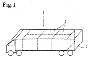
- containers 3 of an identical shape are loaded in a front-to-rear and right-to-left arrangement on a load-carrying platform 2 of a truck 1.
- a personal computer 10 judges whether the containers 3 are loaded in a well-balanced condition on the platform 2. At the same time, the personal computer 10 can determine an arrangement of the containers 3 with a good loading balance.
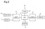
- a central control unit, CPU, 11 executes arithmetic processing by adequately using RAM 13 according to a program stored in ROM 12 as shown in Fig. 2.
- CPU 11 processes input data input from a keyboard 16 or mouse 17 through an input interface 14, and outputs the result of the processing to a display 18 through an output interface 15.
- containers 3 are loaded in m rows and n columns in the front-to-rear and right-to-left directions, namely, in m rows in the traveling direction and n columns in the breadth direction, on the platform 2, and weights (weights of cargoes contained in the containers plus weights of the containers) of containers 3 placed in individual cells of the matrix are shown by affixing subscripts of the cell numbers of the matrix as W 11 , W 12 , ..., W 1n , W 21 , W 22 , ..., W 2n , ..., ..., W m1 , W m2 , ... W mn .
- mxn containers 3 are placed symmetrically about the center C of the platform in a close alignment of m rows and n columns. In this case, heavier containers 3 are placed closer to the platform center C such that the entirety is well-balanced as far as possible in the front-to-rear and right-to-left directions.
- the weights W 11 , W 12 , ..., W 1n , W 21 , W 22 , ..., W 2n , ..., ..., W m1 , W m2 , ... W mn of the containers 3 in the array with m rows and n columns are input into the personal computer 10.
- the personal computer 10 carries out arithmetic operation of the bias load ratio ⁇ in the traveling direction and the bias load ratio ⁇ in the vehicle breadth direction, and judges whether the loading balance is acceptable or not.
- the weights W 11 , W 12 , ..., W 1n , W 21 , W 22 , ..., W 2n , ..., ..., W m1 , W m2 , ... W mn of the containers 3 in the array with m rows and n columns are input into the personal computer 10 together with their addresses in the matrix and ID numbers of the individual containers 3 (step S1).
- step S2 total weights of containers 3 in individual rows, namely, W i , W i-1 , ..., W -i , are calculated (step S2).
- W i denotes the total weight of containers of the row that is distant forward by i rows from the platform center C
- W -i is the total weight of containers of the row that is distant rearward by i rows from the platform center C.
- moment weight W i ⁇ i obtained by multiplying the total weight W i of containers of the row distant forward by i rows from the platform center C by i and moment weight W -1 ⁇ i obtained by multiplying the total weight W -i of containers of the row distant rearward by i rows from the platform center C are calculated for each row (step S3).
- W j denotes the total weight of containers of the column that is distant leftward by j columns from the platform center C
- W -i is the total weight of containers of the column that is distant rightward by i columns from the platform center C.
- moment weight W i ⁇ j obtained by multiplying the total weight W j of containers of the column distant leftward by j columns from the platform center C by j and moment weight W -j ⁇ j obtained by multiplying the total weight W -j of containers of the column distant rightward by j columns from the platform center C are calculated for each column (step S5).
- CPU calculates the bias load ratio ⁇ in the traveling direction, which is the ratio of the difference
- CPU calculates the bias load ratio ⁇ in the breadth direction, which is the ratio of the difference
- step S8 CPU judges whether or not the bias load ratio ⁇ in the traveling direction is in the range not exceeding 0.08 (8%) (step S8). If it is in the range not exceeding 8%, it goes the step S9.
- step S9 CPU judges whether or not the bias load ratio ⁇ in the breadth direction is in the range not exceeding 0.04 (4%). If it is in the range not exceeding 4%, , it goes to the step S10.
- step S10 the outstanding arrangement of the containers 3 is judged to be well-balanced, and that arrangement is displayed on the display 18 together with ID numbers of the containers 3.
- step S8 If the bias load ratio ⁇ in the traveling direction is judged to exceed 0.08 in step S8 or the bias load ratio ⁇ in the breadth direction is judged to exceed 0.04 in step S9, CPU goes to the step S11 and judges whether the entire change of placement has been completed or not. If it is not yet completed, CPU goes to the step S12 and change placement of containers 3 to modify the matrix arrangement.
- CPU changes the weights W 11 , W 12 , ..., W 1n , W 21 , W 22 , ..., W 2n , ..., ..., W m1 , W m2 , ... W mn of the containers 3 arranged in m rows and n columns and returns to the step S2 to repeat the arithmetic operation, thereby calculate new values of the bias load ratio ⁇ in the traveling direction and the bias load ratio ⁇ in the breadth direction and judge whether the loading balance is adequate or not.
- CPU goes from the step S11 to the step S13, and displays impossibility of any acceptable placement within the condition on the display 18.
- total weights of containers, W 1 , W 0 , W -1 , of individual rows are calculated beforehand as follows.
- Total weight W 1 of containers in the row distant forward by one row from the platform center C W 11 +W 12
- Total weight W 0 of containers in the row passing the platform center C W 21 +W 21
- Total weight W -1 of containers in the row distant rearward from the platform center C W 31 +W 32
- total weights of containers, W 1 , W -1 , of individual columns are calculated beforehand as follows.
- Total weight W 1 of containers in the column distant leftward by one column from the platform center C W 11 +W 21 +W 31
- Total weight W -1 of containers in the column distant rightward by one column from the platform center C W 12 +W 22 +W 32
- moment weights W 1 ⁇ 1, W 0 ⁇ 0, W -1 ⁇ 1 or individual rows and moment weights W 1 ⁇ 1, W -1 1 of individual columns are calculated.
- the bias load ratio ⁇ in the traveling direction is calculated as
- bias load ⁇ in the breadth direction is calculated as
- the bias load ratio ⁇ in the traveling direction and the bias load ratio ⁇ in the breadth direction are easily calculated, and depending upon whether or not the bias load ratio ⁇ in the traveling direction is in the range not exceeding 8% and whether or not the bias load ratio ⁇ in the breadth direction is in the range not exceeding 4%, the computer readily judges whether the loading balance is appropriate or not. Therefore, the method is convenient and very useful.
- containers 3 are allocated to all cells of the matrix because, with any vacant cell, cargoes will not be fixed reliably, and it is intended to prevent such trouble.
Landscapes
- Engineering & Computer Science (AREA)
- Business, Economics & Management (AREA)
- Human Resources & Organizations (AREA)
- Economics (AREA)
- Strategic Management (AREA)
- Quality & Reliability (AREA)
- Physics & Mathematics (AREA)
- Entrepreneurship & Innovation (AREA)
- Marketing (AREA)
- Operations Research (AREA)
- Development Economics (AREA)
- Tourism & Hospitality (AREA)
- Game Theory and Decision Science (AREA)
- General Business, Economics & Management (AREA)
- General Physics & Mathematics (AREA)
- Theoretical Computer Science (AREA)
- Loading Or Unloading Of Vehicles (AREA)
- Warehouses Or Storage Devices (AREA)
- Testing Of Balance (AREA)
- Management, Administration, Business Operations System, And Electronic Commerce (AREA)
Abstract
Description
- This invention relates to a method of loading containers in an optimum way on a load-carrying platform of a platform of a vehicle.
- In case a plurality of containers of the same shape are loaded on a load-carrying platform of a truck, for example, load of containers is often one-sided to the front, rear, right or left side even when loaded in centrally symmetrical placement on the platform due to a difference in weight of cargoes contained in respective containers.
- If a vehicle with one-sided load drives, one-sided centrifugal load may work on the platform while the vehicle goes around a curve, and may therefore degrade the stability.
- To avoid this, for loading containers in one row in the front-to-rear direction, there is proposed a method of weighting respective containers for evaluating the loading balance and determining the optimum front-to-rear position of containers to optimize the front-to-rear loading balance (Japanese Patent Laid-Open Publication No. sho 59-31223).
- This method is directed to loading containers in one row in the front-to-rear direction, and determines the loading pattern such that the sum total of weights of respective containers becomes zero. The containers loaded are equal in weight.
- Further, a method of evaluating the balance upon loading cargoes different in shape was invented earlier by the same inventors of the present invention, and it has been disclosed in Japanese Patent Laid-Open Publication No. hei 8-244981.
- The method disclosed therein divides the loading space into unit spaces each sized equally to the size of the smallest of cargoes to be loaded, then assigns the weight of each cargo to be loaded to each cargo address corresponding to one or more unit spaces, thereafter calculates its moment, and finally calculates the weight balance ratio of the loading space from that moment.
- The prior art of the former publication (Japanese Patent Laid-Open Publication No. sho 59-31223) handling containers equal in weight can load containers such that the sum total of weights becomes zero. This prior art, however, does not teach its application to loading containers different in weight of cargoes contained therein or loading containers in a two-dimensional layout other than the front-to-rear single row, and its applicable range is narrow accordingly.
- The latter prior art (Japanese Patent Laid-Open Publication No. hei 8-24981) relates to loading cargoes not uniform in shape unlike containers, and it is therefore compelled to divide the loading space into unit spaces each sized equally to the size of the smallest of cargoes to be loaded and then assign the weight of each cargo to be loaded to each cargo address corresponding to one or more unit spaces. These steps are very troublesome, and this method is not so practical.
- Taking those problems into consideration, it is an object of the invention to provide an optimum method of loading containers, which is capable of easily determining the optimum loading balance when loading containers various in weight over front-to-rear and right-to-left dimensions, and is therefore very practical.
- To accomplish the object, the invention provides a method of loading containers in an optimum way on a load-carrying platform of a vehicle, in which a plurality of containers identical in shape are loaded in front-to-rear and left-to-right matrix arrangement symmetrically of the platform center, comprising: calculating moment weight Wi · i which is multiplication of total weight Wi of containers in each row distant forward by i rows from the platform center by i; calculating moment weight W-i ·i which is multiplication of total weight W-i of containers in each row distant rearward by i rows from the platform center by i; calculating the bias load ratio in the traveling direction, which is the ratio of the difference |ΣWi · i-ΣW-i · i| between the total ΣWi · i of moment weights of rows located forward of the platform center C and the total ΣW-i · i of moment weights of rows located rearward of the platform center C relative to the sum of same (ΣWi ·i+ΣW-i ·i); calculating moment weight Wj·j which is multiplication of total weight Wj of containers in each column distant leftward by j columns from the platform center by j; calculating moment weight W-j · j which is multiplication of total weight W-j of containers in each column distant rightward by j columns from the platform center by j; calculating the bias load ratio in the breadth direction, which is the ratio of the difference |ΣWj · j-ΣW-j · j| between the total ΣWj · j of moment weights of columns located leftward of the platform center C and the total ΣW-j · j of moment weights of columns located rightward of the platform center C relative to the sum of same (ΣWj · j+ΣW-j · j); and loading the containers such that the calculated bias load ratio in the traveling direction falls within a predetermined range and the calculated bias load ratio in the breadth direction falls within a predetermined range.
- Therefore,
- With the method according to the invention, containers may be loaded such that the bias load ratio in the traveling direction and the bias load ratio in the breadth direction obtained by the calculation fall within predetermined ratios, and the load balance condition can be easily confirmed to be acceptable or not. Therefore, the method is convenient and very practical.
- In the method of loading containers in an optimum way on a load-carrying platform of a vehicle according to the invention, i=0 or j=0 may be assumed for calculation of containers in a column or row that coincides with the center of the load-carrying platform.
- When containers are loaded in odd number rows or odd number columns, the central row or column coincides with the platform center. Then i=0 or j=0 is assumed for calculation.
- That is, the row or column coinciding with the platform center may be regarded not to exist for calculation.
- In the method of loading containers in an optimum way on a load-carrying platform of a vehicle according to the invention, containers are preferably loaded such that the bias load ratio in the traveling direction is limited approximately within 8% and the bias load ratio in the breadth direction is limited within approximately 4 percent.
- If the bias load ratio in the traveling direction is within approximately 8% and the bias load ratio in the breadth direction is approximately within 4%, the loading balance is good, and a vehicle with containers loaded in this condition does not lose stability even when a centrifugal load is applied to its load-carrying platform while it runs along a curve.
-
- Fig. 1 is a perspective view roughly showing a truck with containers loaded on the load-carrying platform thereof, taken as an embodiment of the invention;
- Fig. 2 is a diagram roughly showing a personal computer;
- Fig. 3 is 6 flowchart of arithmetic processing according to an embodiment of the invention;
- Fig. 4 is a diagram that shows an arrangement of containers in m rows and n columns on a load-carrying platform;
- Figs. 5(1) and 5(2) are diagrams each showing total weights of individual rows and individual columns, respectively;
- Fig. 6 is a diagram that shows an arrangement of containers in three rows and two columns on a load-carrying platform; and
- Figs. 7(1) and 7(2) are diagrams each showing total weights of containers of individual rows and individual columns, respectively, in the arrangement of the containers shown in Fig. 6.
-
- An embodiment of the invention will now be described with reference to Figs. 1 through 7.
- As shown in Fig. 1,
containers 3 of an identical shape are loaded in a front-to-rear and right-to-left arrangement on a load-carryingplatform 2 of atruck 1. - A
personal computer 10 judges whether thecontainers 3 are loaded in a well-balanced condition on theplatform 2. At the same time, thepersonal computer 10 can determine an arrangement of thecontainers 3 with a good loading balance. - In the
personal computer 10, a central control unit, CPU, 11 executes arithmetic processing by adequately usingRAM 13 according to a program stored inROM 12 as shown in Fig. 2. -
CPU 11 processes input data input from akeyboard 16 ormouse 17 through aninput interface 14, and outputs the result of the processing to adisplay 18 through anoutput interface 15. - Assume here that, as shown in Fig. 4,
containers 3 are loaded in m rows and n columns in the front-to-rear and right-to-left directions, namely, in m rows in the traveling direction and n columns in the breadth direction, on theplatform 2, and weights (weights of cargoes contained in the containers plus weights of the containers) ofcontainers 3 placed in individual cells of the matrix are shown by affixing subscripts of the cell numbers of the matrix as W11, W12, ..., W1n, W21, W22, ..., W2n, ..., ..., Wm1, Wm2, ... Wmn. - These
mxn containers 3 are placed symmetrically about the center C of the platform in a close alignment of m rows and n columns. In this case,heavier containers 3 are placed closer to the platform center C such that the entirety is well-balanced as far as possible in the front-to-rear and right-to-left directions. - The weights W11, W12, ..., W1n, W21, W22, ..., W2n, ..., ..., Wm1, Wm2, ... Wmn of the
containers 3 in the array with m rows and n columns are input into thepersonal computer 10. Thepersonal computer 10 carries out arithmetic operation of the bias load ratio α in the traveling direction and the bias load ratio β in the vehicle breadth direction, and judges whether the loading balance is acceptable or not. - Procedures of the arithmetic control of the
personal computer 10 are shown in Fig. 3, and explanation will be made below following to the procedures. - First, the weights W11, W12, ..., W1n, W21, W22, ..., W2n, ..., ..., Wm1, Wm2, ... Wmn of the
containers 3 in the array with m rows and n columns are input into thepersonal computer 10 together with their addresses in the matrix and ID numbers of the individual containers 3 (step S1). - After that, as shown in Fig. 5(1), total weights of
containers 3 in individual rows, namely, Wi, Wi-1, ..., W-i, are calculated (step S2). - Wi denotes the total weight of containers of the row that is distant forward by i rows from the platform center C, and W-i is the total weight of containers of the row that is distant rearward by i rows from the platform center C.
- After that, moment weight Wi ·i obtained by multiplying the total weight Wi of containers of the row distant forward by i rows from the platform center C by i and moment weight W-1 ·i obtained by multiplying the total weight W-i of containers of the row distant rearward by i rows from the platform center C are calculated for each row (step S3).
- Similarly, as shown in Fig. 5(2), total weights Wj, W"j-1, ..., W-j of
containers 3 of respective columns are calculated (step S4). - Wj denotes the total weight of containers of the column that is distant leftward by j columns from the platform center C, and W-i is the total weight of containers of the column that is distant rightward by i columns from the platform center C.
- Then, moment weight Wi ·j obtained by multiplying the total weight Wj of containers of the column distant leftward by j columns from the platform center C by j and moment weight W-j ·j obtained by multiplying the total weight W-j of containers of the column distant rightward by j columns from the platform center C are calculated for each column (step S5).
- In the next step S6, CPU calculates the bias load ratio α in the traveling direction, which is the ratio of the difference |ΣWi ·i-ΣW-i ·i| between the total ΣWi ·i of moment weights of rows located forward of the platform center C and the total ΣW-i ·i of moment weights of rows located rearward of the platform center C relative to the sum of them (ΣWi ·i+ΣW-i ·i) is calculated based on the moment weights Wi ·i, W-i ·i of respective rows.
- Similarly, in the next step S7, CPU calculates the bias load ratio β in the breadth direction, which is the ratio of the difference |ΣWj ·j-ΣW-j ·j| between the total ΣWj ·j of moment weights of columns located leftward of the platform center C and the total ΣW-j ·j of moment weights of columns located rightward of the platform center C relative to the sum of them (ΣWj ·j+ΣW-j ·j) is calculated based on the moment weights Wj ·j, W-j ·j of respective columns.
- After calculating the bias load ratio α in the traveling direction and the bias load ratio β in the breadth direction, CPU judges whether or not the bias load ratio α in the traveling direction is in the range not exceeding 0.08 (8%) (step S8). If it is in the range not exceeding 8%, it goes the step S9. In step S9, CPU judges whether or not the bias load ratio β in the breadth direction is in the range not exceeding 0.04 (4%). If it is in the range not exceeding 4%, , it goes to the step S10. In step S10, the outstanding arrangement of the
containers 3 is judged to be well-balanced, and that arrangement is displayed on thedisplay 18 together with ID numbers of thecontainers 3. - If the bias load ratio α in the traveling direction is judged to exceed 0.08 in step S8 or the bias load ratio β in the breadth direction is judged to exceed 0.04 in step S9, CPU goes to the step S11 and judges whether the entire change of placement has been completed or not. If it is not yet completed, CPU goes to the step S12 and change placement of
containers 3 to modify the matrix arrangement. - That is, CPU changes the weights W11, W12, ..., W1n, W21, W22, ..., W2n, ..., ..., Wm1, Wm2, ... Wmn of the
containers 3 arranged in m rows and n columns and returns to the step S2 to repeat the arithmetic operation, thereby calculate new values of the bias load ratio α in the traveling direction and the bias load ratio β in the breadth direction and judge whether the loading balance is adequate or not. - If any arrangement does not satisfy the condition (α≤0.08, β≤0.04) even after the change of placement is repeated, CPU goes from the step S11 to the step S13, and displays impossibility of any acceptable placement within the condition on the
display 18. - In case such impossibility of placement within he condition is displayed, it is necessary to cope with it by, for example, moving cargoes among different containers, reducing one or more of containers, or replacing one or more of containers with one or more other containers together with cargoes therein, if possible.
- Here is taken an example in which six
containers 3 are loaded on the load-carryingplatform 2 of thetruck 1 as shown in Fig. 6. Assume that these sixcontainers 3 are loaded in three rows and two columns in the front-to-rear and right-to-left directions, namely in three rows in the traveling direction and two columns in the breadth direction. Thus the weights W11, W12, W21, W22, W31, W32 of containers are allocated to respective cells. - These six
containers 3 are placed symmetrically of the platform center C in a close alignment of three rows and two columns, while locatingheavier containers 3 closer to the platform center C for a balance as best as possible in the front-to-rear and right-to-left directions. - As shown in Fig. 7(1), total weights of containers, W1, W0, W-1, of individual rows are calculated beforehand as follows.
Total weight W1 of containers in the row distant forward by one row from the platform center C = W11+W12
Total weight W0 of containers in the row passing the platform center C = W21+W21
Total weight W-1 of containers in the row distant rearward from the platform center C = W31+W32 - Similarly, total weights of containers, W1, W-1, of individual columns are calculated beforehand as follows.
Total weight W1 of containers in the column distant leftward by one column from the platform center C = W11+W21+W31
Total weight W-1 of containers in the column distant rightward by one column from the platform center C = W12+W22+W32 - After that, moment weights W1 ·1, W0 ·0, W-1·1 or individual rows and moment weights W1 ·1,
W -11 of individual columns are calculated. - Based on those values, the bias load ratio α in the traveling direction is calculated as

- Further, the bias load β in the breadth direction is calculated as

- As appreciated from the calculation of the bias load ratio α in the traveling direction, since the row or column passing the platform center C is calculated as i=0 or j=0, its moment weight becomes 0, and its may be excluded from the calculation.
- As explained above, by simply inputting weights of
containers 3 to be allocated in individual cells of the matrix, the bias load ratio α in the traveling direction and the bias load ratio β in the breadth direction are easily calculated, and depending upon whether or not the bias load ratio α in the traveling direction is in the range not exceeding 8% and whether or not the bias load ratio β in the breadth direction is in the range not exceeding 4%, the computer readily judges whether the loading balance is appropriate or not. Therefore, the method is convenient and very useful. - Therefore, any operator even not skilled can pursue the operation.
- Additionally, since the above-explained arithmetic control automatically finds out a placement of containers satisfying the condition (α≤0.08, β≤0.04), it is so much more convenient.
- Only if the
containers 3 are loaded on the platform to satisfy this condition (α≤0.08, β≤0.04), the loading balance is adequate, and the vehicle does not lose stability even when a centrifugal load is applied to theplatform 2 while it runs along a curve. - Although the embodiment has been described as placing
containers 3 in a matrix in the front-to-rear and right-to-left directions without stacking them vertically, the same arithmetic operation can be used by regarding the total weight of containers stacked in each cell of the matrix as the weight of a single container. - Consequently, it is the premise of the above-described method that
containers 3 are allocated to all cells of the matrix because, with any vacant cell, cargoes will not be fixed reliably, and it is intended to prevent such trouble. - If containers to be transported are insufficient to fill all cells, then a fixture material will be needed to fill the cells. By using
vacant containers 3 as the fixture material, the same arithmetic operation can be used.
Claims (3)
- A method of loading containers in an optimum way on a load-carrying platform of a vehicle, in which a plurality of containers identical in shape are loaded in front-to-rear and left-to-right matrix arrangement symmetrically of the platform center, comprising the steps of:calculating moment weight Wi ·i which is multiplication of total weight Wi of containers in each row distant forward by i rows from the platform center by i;calculating moment weight W-i ·i which is multiplication of total weight W-i of containers in each row distant rearward by i rows from the platform center by i;calculating the bias load ratio in the traveling direction, which is the ratio of the difference |ΣWi · i-ΣW-1 · i| between the total ΣWi · i of moment weights of rows located forward of the platform center C and the total ΣW-i · i of moment weights of rows located rearward of the platform center C relative to the sum of same (ΣWi ·i+ΣW-i ·i);calculating moment weight Wj ·j which is multiplication of total weight Wj of containers in each column distant leftward by j columns from the platform center by j;calculating moment weight W-j · j which is multiplication of total weight W-j of containers in each column distant rightward by j columns from the platform center by j;calculating the bias load ratio in the breadth direction, which is the ratio of the difference |ΣWj · j-ΣW-j · j| between the total ΣWj · j of moment weights of columns located leftward of the platform center C and the total ΣW-j · j of moment weights of columns located rightward of the platform center C relative to the sum of same (ΣWj · j+ΣW-j · j); andloading the containers such that the calculated bias load ratio in the traveling direction falls within a predetermined range and the calculated bias load ratio in the breadth direction falls witnin a predetermined range.
- A method of loading containers in an optimum way on a load-carrying platform of a vehicle according to claim 1, wherein calculation is carried out by regarding i=0 or j=0 for containers in the row or column passing the platform center.
- A method of loading containers in an optimum way on a load-carrying platform of a vehicle according to claim 2, wherein the containers are loaded such that the bias load ratio in the traveling direction is in a range not exceeding approximately 8% and the bias load ratio in the breadth direction is in a range not exceeding approximately 4%.
Applications Claiming Priority (3)
| Application Number | Priority Date | Filing Date | Title |
|---|---|---|---|
| JP2001339213 | 2001-11-05 | ||
| JP2001339213A JP2003146445A (en) | 2001-11-05 | 2001-11-05 | Optimal loading method of containers on the vehicle bed |
| PCT/JP2002/010783 WO2003040007A1 (en) | 2001-11-05 | 2002-10-17 | Optimum method of loading containers onto vehicle platform |
Publications (2)
| Publication Number | Publication Date |
|---|---|
| EP1443005A1 true EP1443005A1 (en) | 2004-08-04 |
| EP1443005A4 EP1443005A4 (en) | 2007-05-23 |
Family
ID=19153596
Family Applications (1)
| Application Number | Title | Priority Date | Filing Date |
|---|---|---|---|
| EP02802701A Withdrawn EP1443005A4 (en) | 2001-11-05 | 2002-10-17 | Optimum method of loading containers onto vehicle platform |
Country Status (6)
| Country | Link |
|---|---|
| US (1) | US6678576B2 (en) |
| EP (1) | EP1443005A4 (en) |
| JP (1) | JP2003146445A (en) |
| CN (1) | CN1219689C (en) |
| BR (1) | BR0206294A (en) |
| WO (1) | WO2003040007A1 (en) |
Cited By (1)
| Publication number | Priority date | Publication date | Assignee | Title |
|---|---|---|---|---|
| WO2015026075A1 (en) * | 2013-08-20 | 2015-02-26 | 주식회사 우영에스엔엘 | Freight loading simulation device and method |
Families Citing this family (6)
| Publication number | Priority date | Publication date | Assignee | Title |
|---|---|---|---|---|
| JP2006273464A (en) * | 2005-03-28 | 2006-10-12 | Toyoda Suchiirusentaa Kk | Loading information preparing device, loading information preparing method using the same, method for carrying conveyance object into transportation container, physical distribution control system, computer-readable storing medium used for these and its program |
| US8321258B2 (en) * | 2006-08-31 | 2012-11-27 | Sap Aktiengeselleschaft | Vehicle scheduling and routing with compartments |
| EP2104112A1 (en) | 2008-03-17 | 2009-09-23 | Atomic Energy Council - Institute of Nuclear Energy Research | Method for selecting and configuring spent nuclear fuel bundles with the view of disposing the same in casks |
| CN103299196B (en) * | 2010-12-28 | 2015-06-24 | 株式会社日立高新技术 | Centrifugal separation device, pretreatment system provided with centrifugal separation device, and control method for the system |
| US20140343910A1 (en) * | 2013-05-17 | 2014-11-20 | The Procter & Gamble Company | Method to determine unit load stability |
| CN114275561B (en) * | 2021-12-27 | 2022-09-16 | 华中科技大学 | Multi-batch cargo loading method for van and application |
Family Cites Families (5)
| Publication number | Priority date | Publication date | Assignee | Title |
|---|---|---|---|---|
| JPS5931223A (en) * | 1982-08-16 | 1984-02-20 | Hitachi Ltd | Control method for loading on transport equipment and device thereof |
| US4640657A (en) * | 1984-09-10 | 1987-02-03 | Moore Robert W | Carton loading method and system |
| US5322350A (en) * | 1992-02-21 | 1994-06-21 | Solite Corporation | Truck for alternately handling comminuted and palletized cargo |
| JPH06179526A (en) * | 1992-12-11 | 1994-06-28 | Nippon Steel Corp | Physical distribution control method in iron and steel industry |
| JPH08244981A (en) * | 1995-03-16 | 1996-09-24 | Honda Motor Co Ltd | Cargo loading balance evaluation method |
-
2001
- 2001-11-05 JP JP2001339213A patent/JP2003146445A/en active Pending
-
2002
- 2002-10-17 WO PCT/JP2002/010783 patent/WO2003040007A1/en not_active Ceased
- 2002-10-17 CN CNB028034511A patent/CN1219689C/en not_active Expired - Fee Related
- 2002-10-17 EP EP02802701A patent/EP1443005A4/en not_active Withdrawn
- 2002-10-17 BR BR0206294-1A patent/BR0206294A/en not_active Application Discontinuation
- 2002-10-24 US US10/278,848 patent/US6678576B2/en not_active Expired - Fee Related
Non-Patent Citations (2)
| Title |
|---|
| No further relevant documents disclosed * |
| See also references of WO03040007A1 * |
Cited By (1)
| Publication number | Priority date | Publication date | Assignee | Title |
|---|---|---|---|---|
| WO2015026075A1 (en) * | 2013-08-20 | 2015-02-26 | 주식회사 우영에스엔엘 | Freight loading simulation device and method |
Also Published As
| Publication number | Publication date |
|---|---|
| US6678576B2 (en) | 2004-01-13 |
| CN1219689C (en) | 2005-09-21 |
| BR0206294A (en) | 2004-02-03 |
| EP1443005A4 (en) | 2007-05-23 |
| CN1484605A (en) | 2004-03-24 |
| US20030086781A1 (en) | 2003-05-08 |
| JP2003146445A (en) | 2003-05-21 |
| WO2003040007A1 (en) | 2003-05-15 |
Similar Documents
| Publication | Publication Date | Title |
|---|---|---|
| KR101384739B1 (en) | Method for loading in container by considering weight balances | |
| US6678576B2 (en) | Method of loading containers in an optimum way on a load-carrying platform of a vehicle | |
| EP3953866A1 (en) | Event-driven spiking convolutional neural network | |
| JPH02286503A (en) | Arranging method of object and apparatus | |
| CN112926808A (en) | Logistics path planning method, device, equipment and computer readable storage medium | |
| CN110544019B (en) | Container cargo loading method and system for intelligent ship | |
| JP7468337B2 (en) | Information processing device, optimization method, and optimization program | |
| JP7484556B2 (en) | Information processing device, optimization method, and optimization program | |
| US5265043A (en) | Wallace tree multiplier array having an improved layout topology | |
| CN116040331B (en) | Cargo palletizing methods and apparatus, handling equipment and computer-readable storage media | |
| JPH03197826A (en) | Combination scale | |
| JPH08244981A (en) | Cargo loading balance evaluation method | |
| JPH0671939B2 (en) | Luggage loading judgment processing method | |
| JPH0395028A (en) | How to stow cargo in a stowage space using a computer | |
| JP2012051696A (en) | Stacking information generating device | |
| JP4698955B2 (en) | Additional weight determination device for combination weighers | |
| JP2780385B2 (en) | Loading planning device | |
| JP6193182B2 (en) | Process load adjustment method, process load adjustment program, and process load adjustment apparatus | |
| CN118458417B (en) | Automatic operation control method and system for ship loader | |
| JPS586841A (en) | Product loading planning device for vehicles | |
| US7397951B2 (en) | Image processing device and image processing method | |
| CN120494297B (en) | Container unloading stacking planning method, device, equipment and storage medium | |
| JP4337998B2 (en) | Loading method and loading device | |
| JP2777966B2 (en) | How to plan your stowage | |
| CN120067701A (en) | Automatic layout and stack shape generation method and equipment for robot stacking and storage medium |
Legal Events
| Date | Code | Title | Description |
|---|---|---|---|
| PUAI | Public reference made under article 153(3) epc to a published international application that has entered the european phase |
Free format text: ORIGINAL CODE: 0009012 |
|
| 17P | Request for examination filed |
Effective date: 20030630 |
|
| AK | Designated contracting states |
Kind code of ref document: A1 Designated state(s): AT BE BG CH CY CZ DE DK EE ES FI FR GB GR IE IT LI LU MC NL PT SE SK TR |
|
| A4 | Supplementary search report drawn up and despatched |
Effective date: 20070419 |
|
| RIC1 | Information provided on ipc code assigned before grant |
Ipc: B65G 67/04 20060101ALN20070413BHEP Ipc: B65G 69/00 20060101AFI20070413BHEP |
|
| STAA | Information on the status of an ep patent application or granted ep patent |
Free format text: STATUS: THE APPLICATION HAS BEEN WITHDRAWN |
|
| REG | Reference to a national code |
Ref country code: DE Ref legal event code: 8566 |
|
| 18W | Application withdrawn |
Effective date: 20070625 |