EP1442929A2 - Operation lever structure of lever switch - Google Patents
Operation lever structure of lever switch Download PDFInfo
- Publication number
- EP1442929A2 EP1442929A2 EP04000284A EP04000284A EP1442929A2 EP 1442929 A2 EP1442929 A2 EP 1442929A2 EP 04000284 A EP04000284 A EP 04000284A EP 04000284 A EP04000284 A EP 04000284A EP 1442929 A2 EP1442929 A2 EP 1442929A2
- Authority
- EP
- European Patent Office
- Prior art keywords
- lever
- knob
- guide
- guide ribs
- pair
- Prior art date
- Legal status (The legal status is an assumption and is not a legal conclusion. Google has not performed a legal analysis and makes no representation as to the accuracy of the status listed.)
- Withdrawn
Links
Images


Classifications
-
- H—ELECTRICITY
- H01—ELECTRIC ELEMENTS
- H01H—ELECTRIC SWITCHES; RELAYS; SELECTORS; EMERGENCY PROTECTIVE DEVICES
- H01H25/00—Switches with compound movement of handle or other operating part
- H01H25/04—Operating part movable angularly in more than one plane, e.g. joystick
-
- B—PERFORMING OPERATIONS; TRANSPORTING
- B60—VEHICLES IN GENERAL
- B60Q—ARRANGEMENT OF SIGNALLING OR LIGHTING DEVICES, THE MOUNTING OR SUPPORTING THEREOF OR CIRCUITS THEREFOR, FOR VEHICLES IN GENERAL
- B60Q1/00—Arrangement of optical signalling or lighting devices, the mounting or supporting thereof or circuits therefor
- B60Q1/02—Arrangement of optical signalling or lighting devices, the mounting or supporting thereof or circuits therefor the devices being primarily intended to illuminate the way ahead or to illuminate other areas of way or environments
- B60Q1/04—Arrangement of optical signalling or lighting devices, the mounting or supporting thereof or circuits therefor the devices being primarily intended to illuminate the way ahead or to illuminate other areas of way or environments the devices being headlights
- B60Q1/14—Arrangement of optical signalling or lighting devices, the mounting or supporting thereof or circuits therefor the devices being primarily intended to illuminate the way ahead or to illuminate other areas of way or environments the devices being headlights having dimming means
- B60Q1/1446—Arrangement of optical signalling or lighting devices, the mounting or supporting thereof or circuits therefor the devices being primarily intended to illuminate the way ahead or to illuminate other areas of way or environments the devices being headlights having dimming means controlled by mechanically actuated switches
- B60Q1/1453—Hand actuated switches
- B60Q1/1461—Multifunction switches for dimming headlights and controlling additional devices, e.g. for controlling direction indicating lights
- B60Q1/1469—Multifunction switches for dimming headlights and controlling additional devices, e.g. for controlling direction indicating lights controlled by or attached to a single lever, e.g. steering column stalk switches
-
- H—ELECTRICITY
- H01—ELECTRIC ELEMENTS
- H01H—ELECTRIC SWITCHES; RELAYS; SELECTORS; EMERGENCY PROTECTIVE DEVICES
- H01H9/00—Details of switching devices, not covered by groups H01H1/00 - H01H7/00
- H01H9/02—Bases, casings, or covers
- H01H9/06—Casing of switch constituted by a handle serving a purpose other than the actuation of the switch, e.g. by the handle of a vacuum cleaner
- H01H2009/066—Casing of switch constituted by a handle serving a purpose other than the actuation of the switch, e.g. by the handle of a vacuum cleaner having switches mounted on a control handle, e.g. gear shift lever
Definitions
- the present invention relates to an operation lever structure of a lever switch and particularly to an operation lever structure of a combination switch for an automobile.
- Japanese Unexamined Patent Publications No. 2000-322982 and No. 2000-195380 disclose an operation lever structure of a lever switch for a vehicle, for example, a combination switch for an automobile as the related art as shown in Fig. 5 - Fig. 9.
- An operation lever 1 as shown in Fig. 5 - Fig. 9, is equipped with a substantially cylindrical knob 2, a substantially cylindrical lever guide 3 inserted into the knob 2, a pair of rotation knobs 5, 6 rotatably supported through a stationary knob 4 in a tip of the lever guide 3, and harnesses 7 inserted between an inner surface 2a of the knob 2 and an outer surface 3a of the lever guide 3.
- ribs 3b are formed integrating with and projecting from the outer surface 3a of the lever guide 3 at an upper and center part, and both of a left hand side and a right hand side in the outer surface 3a thereof where the ribs 3b extend to the inner surface 2a of the knob 2, as well as a pair of guide ribs 3c, 3c are formed projecting from and integrating with a lower part of the outer surface 3a of the lever guide 3 where the pair of the guide ribs 3c, 3c extend to the inner surface 2a of the knob 2. Harnesses 7 are inserted in a space defined by the outer surface 3a of the lever guide 3, the pair of the guide ribs 3c, 3c, and the inner surface 2a of the knob 2.
- a connector 8 secured to an end of the harnesses 7 is connected to a terminal (not shown) in a side of the rotation knob 6 and another end of the harnesses 7 is connected to a combination switch 9 and the like.
- a base of the lever guide 3 is mounted to a combination switch 9, thereby to carry out a switching connection with various functions based upon operating the knob 2 into which the lever guide 3 is inserted, in the right and left directions, as well as the upward and downward directions.
- An aspect of the present invention provides an operation lever structure of a lever switch, which can obtain good assembling performance.
- An aspect of the present invention is basically attained by providing an operation lever structure of a lever switch comprising:
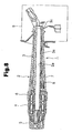
- Fig. 1 is a cross sectional view illustrating a state of an operation lever of a combination switch for a vehicle prior to assembly thereof according to an embodiment of the invention.
- Fig. 2 is a side elevation view from the direction of an arrow A showing a portion of the operation lever after assembly thereof.
- Fig. 3 is a cross sectional view of the operation lever.
- Fig. 4 is a plan view of the operation lever.
- an operation lever 10 is used a lever switch for a vehicle, for example, a combination switch for an automobile comprises a substantially cylindrical knob 11 made of synthetic resin, a substantially cylindrical lever guide 12 made of synthetic resin inserted into the knob 11 a pair of rotation knobs 14, 15 made of synthetic resin rotatably supported through a stationary knob 13 made of synthetic resin in a tip of the lever guide 12, a shaft 19 that rotates inside the lever guide 12, thereby to transmit rotation of the rotation knob 14 to a switch unit 20, and a plurality of harnesses 16 inserted between an inner surface 11a of the knob 11 and an outer surface 12a of the lever guide 12.
- ribs 12b are formed projecting from and integrating with the outer surface 12a of the lever guide 12 at an upper and center part, and both of a left hand side and a right hand side in the outer surface 12a thereof where the ribs 12b extend to the inner surface 11a of the knob 11, as well as a pair of guide ribs 12c,12c are formed projecting from and integrating with a lower part of the outer surface 12a where the pair of the guide ribs 12c, 12c extend to the inner surface 11a of the knob 11.
- a pair of guide ribs 11c, 11c are formed integrating with and projecting from the knob 11 at a location inside the inner surface 11a thereof opposed to the pair of the guide ribs 12c, 12c of the lever guide 12 where the pair of the guide ribs 11c, 11c extend to the outer surface 12a of the lever guide 12 between the pair of the guide ribs 12c, 12c. That is, the pair of the guide ribs 11c, 11c of the knob 11 are adapted to be fitted inside the pair of the guide ribs 12c, 12c of the lever guide 12.
- harnesses 16 penetrate through a space defined by the outer surface 12a of the lever guide 12, the inner surface 11a of the knob 11, and the pair of the guide ribs 11c, 11c of the knob 11.
- a connector 17 secured to an end 16a of the harnesses 16 is connected to a terminal (not shown) disposed in a side of the rotation knob 15.
- Another end 16b of the harnesses 16 is connected to a combination switch 20 and the like.
- a base of the lever guide 12 is mounted to the combination switch 20 through a bell mouth of a boot 18 wherein a switching connection of a switch equipped with various functions is performed by operating the knob 11 into which the lever guide 12 is inserted, in the right and left directions, and the upward and downward directions.
- the harnesses 16 are inserted between the pair of the guide ribs 11c, 11c of the knob 11 and then the lever guide 12 is inserted and assembled therein, pulling downward the both ends 16a, 16b of the harnesses 16 as shown by an arrow in Fig. 1.
- the harnesses 16 are assembled without being separated between the pair of the guide ribs 11c, 11c, and the inner surface 11a of the knob 11.
- the pair of the guide ribs 11c, 11c are formed integrating with and projecting from the knob 11 at the location opposed to the pair of the guide ribs 12c, 12c of the lever guide 12 where the pair of the guide ribs 11c, 11c of the knob extend to the outer surface 12a of the lever guide 12 between the pair of the guide ribs 12c, 12c, and the harnesses 16 penetrate through a space defined by the outer surface 12a of the lever guide 12, the inner surface 11a of the knob 11, and the pair of the guide ribs 11c, 11c of the knob 11, sandwiching the harnesses 16 between the inner surface 11a of the knob 11 and each of the guide ribs 12c, 12c is surely prevented, as well as a damage of the harnesses 16 caused by the sandwich thereof is prevented. Thereby the operation lever 10 with high quality can be manufactured at a low cost.
- a combination switch for an automobile as a lever switch for a vehicle is explained but the embodiment may be applied to a lever switch other than a combination switch for an automobile.
Landscapes
- Engineering & Computer Science (AREA)
- Mechanical Engineering (AREA)
- Switches With Compound Operations (AREA)
Abstract
Description
Claims (4)
- An operation lever structure of a lever switch comprising:a substantially cylindrical knob;a lever guide inserted into the knob;a harness inserted between an inner surface of the knob and an outer surface of thelever guide; anda plurality of first guide ribs disposed in the outer surface of the lever guide, the first guide ribs extending toward the inner surface of the knob, wherein the harness is inserted between the first guide ribs, the operation lever structure comprising:a pair of second guide ribs disposed in the knob at a position inside the inner surface of the knob opposed to the first guide ribs, the second guide ribs extending toward the outer surface of the lever guide between the first guide ribs, wherein the harness is inserted between the second guide ribs.
- An operation lever structure of a lever switch comprising:a substantially cylindrical knob;a lever guide inserted into the knob;a harness inserted between an inner surface of the knob and an outer surface of the lever guide; anda pair of first guide ribs disposed in the outer surface of the lever guide, the first guide ribs extending to the inner surface of the knob, wherein the harness is inserted between the first guide ribs, the operation lever structure comprising:a pair of second guide ribs disposed in the knob at a position inside the inner surface of the knob opposed to the first guide ribs, the second guide ribs extending to the outer surface of the lever guide between the first guide ribs, wherein the harness is inserted between the second guide ribs.
- An operation lever structure as defined in claim 2, wherein
the second guide ribs are inserted and fitted into an inside of the first guide ribs. - An operation lever structure as defined in claim 3, wherein
the operation lever structure of the lever switch is used for a combination switch for an automobile.
Applications Claiming Priority (2)
| Application Number | Priority Date | Filing Date | Title |
|---|---|---|---|
| JP2003021737 | 2003-01-30 | ||
| JP2003021737A JP2004235002A (en) | 2003-01-30 | 2003-01-30 | Operation lever structure of vehicle lever switch |
Publications (2)
| Publication Number | Publication Date |
|---|---|
| EP1442929A2 true EP1442929A2 (en) | 2004-08-04 |
| EP1442929A3 EP1442929A3 (en) | 2006-07-19 |
Family
ID=32652886
Family Applications (1)
| Application Number | Title | Priority Date | Filing Date |
|---|---|---|---|
| EP04000284A Withdrawn EP1442929A3 (en) | 2003-01-30 | 2004-01-09 | Operation lever structure of lever switch |
Country Status (4)
| Country | Link |
|---|---|
| US (1) | US7019232B2 (en) |
| EP (1) | EP1442929A3 (en) |
| JP (1) | JP2004235002A (en) |
| CN (1) | CN100431078C (en) |
Families Citing this family (1)
| Publication number | Priority date | Publication date | Assignee | Title |
|---|---|---|---|---|
| JP6266550B2 (en) * | 2015-02-25 | 2018-01-24 | 株式会社東海理化電機製作所 | Switch device |
Family Cites Families (16)
| Publication number | Priority date | Publication date | Assignee | Title |
|---|---|---|---|---|
| FR2600286B1 (en) * | 1986-06-23 | 1988-10-21 | Jaeger | HANDLE FOR CONTROLLING SWITCHES, PARTICULARLY FOR MOTOR VEHICLES, AND GUIDING PART FOR THE PRODUCTION OF THIS HANDLE |
| US4849585A (en) * | 1988-07-29 | 1989-07-18 | United Technologies Automotive, Inc. | Modularly constructed vehicle control stalk with interchangeable parts and switch assembly |
| JP2547127Y2 (en) * | 1991-07-12 | 1997-09-10 | 株式会社東海理化電機製作所 | Lever switch device |
| FR2692854B1 (en) * | 1992-06-29 | 1994-08-19 | Valeo Commutation | Handle for electrical switch, in particular for motor vehicle. |
| JPH0643981U (en) * | 1992-11-10 | 1994-06-10 | 株式会社東海理化電機製作所 | Lever switch device |
| JP3727378B2 (en) * | 1995-04-28 | 2005-12-14 | ナイルス株式会社 | Lever switch for vehicle |
| JP3172658B2 (en) * | 1995-07-05 | 2001-06-04 | ナイルス部品株式会社 | Lever switch device |
| US5977494A (en) * | 1995-09-08 | 1999-11-02 | Yazaki Corporation | Symmetrically mounted switches on steering wheel column body including wiring connection and control unit |
| DE19538767A1 (en) * | 1995-10-18 | 1997-04-24 | Teves Gmbh Alfred | Switches with flexible conductor foil as a fixed contact and connection to connection contacts |
| JP4104179B2 (en) * | 1996-02-20 | 2008-06-18 | アルプス電気株式会社 | Vehicle knob switch |
| JP2000195380A (en) | 1998-12-25 | 2000-07-14 | Niles Parts Co Ltd | Harness-fixing structure |
| JP3819630B2 (en) * | 1999-03-12 | 2006-09-13 | アルプス電気株式会社 | Stoke lever |
| JP2000322982A (en) | 1999-05-13 | 2000-11-24 | Niles Parts Co Ltd | Vehicular lever switch |
| JP3886783B2 (en) * | 2001-11-20 | 2007-02-28 | 株式会社東海理化電機製作所 | Lever device for vehicle |
| JP3837324B2 (en) * | 2001-11-28 | 2006-10-25 | ナイルス株式会社 | Lever switch structure for vehicles |
| JP4092916B2 (en) * | 2002-01-21 | 2008-05-28 | 松下電器産業株式会社 | Lever switch for vehicle |
-
2003
- 2003-01-30 JP JP2003021737A patent/JP2004235002A/en active Pending
-
2004
- 2004-01-09 EP EP04000284A patent/EP1442929A3/en not_active Withdrawn
- 2004-01-14 US US10/756,400 patent/US7019232B2/en not_active Expired - Lifetime
- 2004-01-30 CN CNB200410002558XA patent/CN100431078C/en not_active Expired - Fee Related
Also Published As
| Publication number | Publication date |
|---|---|
| CN100431078C (en) | 2008-11-05 |
| CN1519871A (en) | 2004-08-11 |
| US20040149554A1 (en) | 2004-08-05 |
| US7019232B2 (en) | 2006-03-28 |
| JP2004235002A (en) | 2004-08-19 |
| EP1442929A3 (en) | 2006-07-19 |
Similar Documents
| Publication | Publication Date | Title |
|---|---|---|
| US5247849A (en) | Shift lever construction | |
| US4840078A (en) | Steering device for vehicles | |
| JP2005508778A (en) | Automotive equipment module | |
| US20040251695A1 (en) | Outside handle apparatus and connector mechanism | |
| US6022230A (en) | Column switch with rotary connector | |
| US5800191A (en) | Rotary connector mounting structure | |
| US7019232B2 (en) | Operation lever structure of lever switch | |
| US6689971B2 (en) | Stopper for flat cable and mounting structure of flat cable | |
| JP5186305B2 (en) | Waterproof structure of switch device | |
| US20050274562A1 (en) | Switch device | |
| JPH08301126A (en) | Coupling structure of steering wheel and rotary connector | |
| JP2001135443A (en) | Rotating connector | |
| JP3906562B2 (en) | Motor holding device | |
| JP5279445B2 (en) | Latch device | |
| KR100304243B1 (en) | Control switch for automatic transmission | |
| JP2001098800A (en) | Mounting structure of cylinder lock in key cylinder device | |
| JP3408927B2 (en) | Rotating connector | |
| KR100422520B1 (en) | An automotive auto-transmission having a one touch type indicator assembly | |
| US7119293B1 (en) | Wrap around terminal for turn signal switch assembly | |
| JP4422942B2 (en) | Assembly method and structure of lever-type push switch | |
| JPH07169544A (en) | Cable reel | |
| JP2004273250A (en) | Combination switch and its assembling device | |
| KR101545814B1 (en) | Switch for Clutch Pedal of Vehicle | |
| JPH11123949A (en) | Automatic transmission shift lever device for vehicle | |
| EP1528204A1 (en) | Torsion spring assembly |
Legal Events
| Date | Code | Title | Description |
|---|---|---|---|
| PUAI | Public reference made under article 153(3) epc to a published international application that has entered the european phase |
Free format text: ORIGINAL CODE: 0009012 |
|
| AK | Designated contracting states |
Kind code of ref document: A2 Designated state(s): AT BE BG CH CY CZ DE DK EE ES FI FR GB GR HU IE IT LI LU MC NL PT RO SE SI SK TR |
|
| AX | Request for extension of the european patent |
Extension state: AL LT LV MK |
|
| PUAL | Search report despatched |
Free format text: ORIGINAL CODE: 0009013 |
|
| AK | Designated contracting states |
Kind code of ref document: A3 Designated state(s): AT BE BG CH CY CZ DE DK EE ES FI FR GB GR HU IE IT LI LU MC NL PT RO SE SI SK TR |
|
| AX | Request for extension of the european patent |
Extension state: AL LT LV MK |
|
| RIC1 | Information provided on ipc code assigned before grant |
Ipc: H01H 25/04 20060101AFI20060613BHEP |
|
| AKX | Designation fees paid | ||
| STAA | Information on the status of an ep patent application or granted ep patent |
Free format text: STATUS: THE APPLICATION IS DEEMED TO BE WITHDRAWN |
|
| 18D | Application deemed to be withdrawn |
Effective date: 20070120 |
|
| REG | Reference to a national code |
Ref country code: DE Ref legal event code: 8566 |