EP1442923A2 - Seat track assembly and method of manufacture - Google Patents
Seat track assembly and method of manufacture Download PDFInfo
- Publication number
- EP1442923A2 EP1442923A2 EP04001806A EP04001806A EP1442923A2 EP 1442923 A2 EP1442923 A2 EP 1442923A2 EP 04001806 A EP04001806 A EP 04001806A EP 04001806 A EP04001806 A EP 04001806A EP 1442923 A2 EP1442923 A2 EP 1442923A2
- Authority
- EP
- European Patent Office
- Prior art keywords
- bracket
- track
- side walls
- spindle
- upper track
- Prior art date
- Legal status (The legal status is an assumption and is not a legal conclusion. Google has not performed a legal analysis and makes no representation as to the accuracy of the status listed.)
- Withdrawn
Links
Images



Classifications
-
- B—PERFORMING OPERATIONS; TRANSPORTING
- B60—VEHICLES IN GENERAL
- B60N—SEATS SPECIALLY ADAPTED FOR VEHICLES; VEHICLE PASSENGER ACCOMMODATION NOT OTHERWISE PROVIDED FOR
- B60N2/00—Seats specially adapted for vehicles; Arrangement or mounting of seats in vehicles
- B60N2/02—Seats specially adapted for vehicles; Arrangement or mounting of seats in vehicles the seat or part thereof being movable, e.g. adjustable
- B60N2/04—Seats specially adapted for vehicles; Arrangement or mounting of seats in vehicles the seat or part thereof being movable, e.g. adjustable the whole seat being movable
- B60N2/06—Seats specially adapted for vehicles; Arrangement or mounting of seats in vehicles the seat or part thereof being movable, e.g. adjustable the whole seat being movable slidable
- B60N2/07—Slide construction
- B60N2/0702—Slide construction characterised by its cross-section
- B60N2/0715—C or U-shaped
-
- B—PERFORMING OPERATIONS; TRANSPORTING
- B60—VEHICLES IN GENERAL
- B60N—SEATS SPECIALLY ADAPTED FOR VEHICLES; VEHICLE PASSENGER ACCOMMODATION NOT OTHERWISE PROVIDED FOR
- B60N2/00—Seats specially adapted for vehicles; Arrangement or mounting of seats in vehicles
- B60N2/02—Seats specially adapted for vehicles; Arrangement or mounting of seats in vehicles the seat or part thereof being movable, e.g. adjustable
- B60N2/0224—Non-manual adjustments, e.g. with electrical operation
- B60N2/02246—Electric motors therefor
-
- B—PERFORMING OPERATIONS; TRANSPORTING
- B60—VEHICLES IN GENERAL
- B60N—SEATS SPECIALLY ADAPTED FOR VEHICLES; VEHICLE PASSENGER ACCOMMODATION NOT OTHERWISE PROVIDED FOR
- B60N2/00—Seats specially adapted for vehicles; Arrangement or mounting of seats in vehicles
- B60N2/02—Seats specially adapted for vehicles; Arrangement or mounting of seats in vehicles the seat or part thereof being movable, e.g. adjustable
- B60N2/04—Seats specially adapted for vehicles; Arrangement or mounting of seats in vehicles the seat or part thereof being movable, e.g. adjustable the whole seat being movable
- B60N2/06—Seats specially adapted for vehicles; Arrangement or mounting of seats in vehicles the seat or part thereof being movable, e.g. adjustable the whole seat being movable slidable
- B60N2/067—Seats specially adapted for vehicles; Arrangement or mounting of seats in vehicles the seat or part thereof being movable, e.g. adjustable the whole seat being movable slidable by linear actuators, e.g. linear screw mechanisms
-
- B—PERFORMING OPERATIONS; TRANSPORTING
- B60—VEHICLES IN GENERAL
- B60N—SEATS SPECIALLY ADAPTED FOR VEHICLES; VEHICLE PASSENGER ACCOMMODATION NOT OTHERWISE PROVIDED FOR
- B60N2/00—Seats specially adapted for vehicles; Arrangement or mounting of seats in vehicles
- B60N2/02—Seats specially adapted for vehicles; Arrangement or mounting of seats in vehicles the seat or part thereof being movable, e.g. adjustable
- B60N2/04—Seats specially adapted for vehicles; Arrangement or mounting of seats in vehicles the seat or part thereof being movable, e.g. adjustable the whole seat being movable
- B60N2/06—Seats specially adapted for vehicles; Arrangement or mounting of seats in vehicles the seat or part thereof being movable, e.g. adjustable the whole seat being movable slidable
- B60N2/07—Slide construction
- B60N2/0702—Slide construction characterised by its cross-section
- B60N2/071—T-shaped
-
- B—PERFORMING OPERATIONS; TRANSPORTING
- B60—VEHICLES IN GENERAL
- B60N—SEATS SPECIALLY ADAPTED FOR VEHICLES; VEHICLE PASSENGER ACCOMMODATION NOT OTHERWISE PROVIDED FOR
- B60N2/00—Seats specially adapted for vehicles; Arrangement or mounting of seats in vehicles
- B60N2/02—Seats specially adapted for vehicles; Arrangement or mounting of seats in vehicles the seat or part thereof being movable, e.g. adjustable
- B60N2/04—Seats specially adapted for vehicles; Arrangement or mounting of seats in vehicles the seat or part thereof being movable, e.g. adjustable the whole seat being movable
- B60N2/06—Seats specially adapted for vehicles; Arrangement or mounting of seats in vehicles the seat or part thereof being movable, e.g. adjustable the whole seat being movable slidable
- B60N2/07—Slide construction
- B60N2/0722—Constructive details
- B60N2/073—Reinforcement members preventing slide dislocation
Definitions
- the present invention relates to seat track assemblies used in positioner mechanisms for automobile seats.
- Automotive powered seat positioning mechanisms are known of the type using a threaded spindle engaged by a gear nut carried by an upper track, with the gear nut driven by a worm gearing in turn driven by a motor. Rotation of the gear nut causes the gear nut and an enclosing gear case to drive the upper track so as to be advanced in either direction along the spindle.
- Such mechanisms are described in U.S. Patent 4,802,374 and WO 9951456.
- the gear nut and worm gear are typically carried in a gear casing mounted on a U-shaped bracket having its legs attached to the upper track to cause the movement of the gear nut to drive the upper track in either direction.
- the spindle is mounted spaced above the bottom wall of a lower track on a pair of brackets each located at an opposite end of the spindle, these brackets in turn attached to the lower track.
- the automobile seat is held in any adjusted position by the gear nut and spindle and these components are thus subjected to high loads in the event of a crash or other high stress event and the support for these components must therefore be designed to have adequate strength to resist the stresses imposed.
- the seat adjustment mechanism be fully functional after a crash.
- the bracket supporting the gear nut and gear casing tends to be distorted as the upper track supporting the seat and the occupant tends to move forward in a crash or other high stress event, and this is resisted by the gear nut-spindle engagement, applying of forces offset from the point of attachment to the upper track.
- the unattached lower ends of the legs of the bracket cannot effectively resist these forces.
- the bottom location of the leg connecting portion of the bracket prevents any fastener attachment to the side walls of the upper track after assembly since that portion is then completely inaccessible.
- heavy gauge steel must be employed to construct the bracket to resist the forces applied in this manner.
- the spindle itself must be well anchored to resist these stresses, which typically is done by a heavy gauge bracket mounted at each end of the spindle. These sturdy brackets must in turn be securely attached to the lower track.
- a track assembly including nested upper and lower channel shaped tracks.
- the upper track and gear case bracket also have portions which are configured to be interfit together when the upper track is placed over the bracket which creates a connection therebetween resisting relative displacement therebetween in the lengthwise direction of the track.
- the upper track has side walls and a top wall to which an upper end of the bracket is fixed after the upper track is installed onto the bracket.
- the interfit portions of the bracket may comprise a pair of protrusions projecting side ways in opposite directions from a respective side of bracket leg connecting portion located at the bottom of the bracket. These protrusions may comprise tabs or teeth which are received in a complementarily shaped notch in a bottom edge of each upper track sidewall, when the upper track is placed over the bracket during assembly.
- This design secures both the top and bottom portions of the bracket relative to the upper track so as to efficiently resist the tendency of the bracket to be deformed under the stresses developed in a crash event.
- the spindle itself is anchored at one end by being flattened at one end with an offset locating the flattened end against the lower track bottom wall so that the spindle is spaced above the bottom track bottom wall.
- the flattened end is directly attached to the lower track bottom wall with fasteners which can also attach the lower track to the floor pan or a separate mounting bracket.
- Figure 1 illustrates the mounting of an automotive seat 10 on a pair of parallel track assemblies 12 secured to the vehicle floor pan 14 and to the seat bottom 16 in conventional fashion.
- a separate mounting bracket (not shown) may also be used rather than a direct attachment to the floor pan.
- a rotary drive system 18 is employed to simultaneously drive an upper track 20 of each track assembly 12 to move the seat forward or backwards in the well known manner on a lower track 24 comprised of an upward facing channel within which the upper track 20 is nested.
- each of the upper tracks 20 are driven by rotation of an associated threaded horizontal spindle 22 mounted to the lower track 24 of each track assembly 12 extending in a lengthwise direction, and a gear nut 26 is threaded onto the spindle 22 (Figure 3).
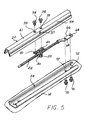
- the gear nut 26 is rotatable within a gear casing 28 ( Figure 7) and has a lengthwise driving engagement with the upper track 20 by being captured between the straddling legs 44 of a U-shaped bracket 30 attached to the upper track 20.
- the gear case 28 may be made of two die cast parts assembled together using integral alignment posts as indicated on one part received in mating holes in the other part as per a common manufacturing practice.
- a worm gear 34 is also rotatably held in the gear casing 28 rotated by the drive system 18 by a cable or shaft (not shown) mating with a square drive socket in the ends of the worm gear.
- the cable or shaft can pass through an opening 36 ( Figure 7) in the side of the gear casing 28 from the side of each upper track 20.
- An aligned hole 37 is also provided in each side wall 54 of the upper track 20 for this same purpose.
- Each bracket 30 has a pair of mounting flanges 32 each located at the top of a respective leg 44, and each having a hole 40 receiving a screw 38 passing through an aligned hole 39 in the upper wall 41 of the upper track 20 to be secured thereto.
- the parallel legs 44 each extend down from a respective flange 32 (best seen in Figure 7) and are connected together at their lower ends with a connecting portion 46.
- the legs 44 have aligned holes 48 to accommodate passage of the spindle 22.
- the bracket 30 has a pair of protrusions 50 which may be comprised of tab or tooth features each projecting laterally out in an opposite direction towards a respective upper track side wall 54 from a respective side edge of the connecting portion 46 of the bracket 30 ( Figures 3 and 6).
- the upper track 20 comprises a downwardly facing elongated channel section nested within the lower track 24 which comprises an upwardly facing elongated channel section as best seen in Figure 3.
- the upper track 20 is slidably mounted on the lower track 24 by a bearing arrangement as described in detail in U.S. Patent 6,557,809 B2, assigned to the assignee of the present application.
- This arrangement includes a reversely formed lip 52 extending up from a rolled bottom edge 74 of each side wall 54 of the upper track 20 ( Figure 3).
- An angled portion 56 of the lip 52 faces an angled portion 58 of each side wall 60 of the lower track 20 to create a roughly square bearing space into which are disposed "load transmission elements", here shown as balls 62.
- An interference is created so that at least one of the tracks is resiliently deflected by the balls 62, as described in detail in U.S. Patent 6,557,809 B2.
- each of the upper track side walls 54 are formed with recesses here shown as notches 64, which are shaped to mate with the protrusions 50 received therein.
- the notches 64 extend horizontally into the rolled edges 74 at the lower end of each side wall 54.
- bracket 30 This interconnection with the bottom edge of the upper track 20 at the lower end of the bracket 30 complements the connection of the upper end of the bracket 30 provided by the later installed fasteners 38 to create a box structure greatly strengthening the ability of the bracket 30 to withstand distorting forces imposed by the nut gear 26 and gear casing 28 in as much as the legs 44 of the bracket 30 are restrained from bending, and the load is shared with the screws 38.
- the bracket 30 can thus be made lighter and is less likely to fail. This connection is achieved without any additional parts or assembly labor.
- the spindle 22 is mounted to the lower track 24 by flattening one end 66 of the spindle 22 (made from alloy steel bar stock).
- the flattened end 66 is pierced with mounting holes 68 to receive screws 70 passing through holes 72 in the bottom wall of the lower track 24 (as well as a section of the vehicle floor pan 14 or separate mounting bracket) to secure the one end of the spindle 22 thereto.
- the spindle 22 is formed with an offsetting transition 76 which positions the spindle 22 spaced above the bottom wall of the lower track 24, as best seen in Figure 4.
- This mounting completely eliminates the spindle brackets used in prior designs which reduces the cost of the track assembly and avoids any possibility of failure by separation of separate brackets in the event of a crash or other high stress event.
- the track assembly is assembled by attaching the spindle to the lower track 24 using screws 70, which at the same time may be attached to the floor pan 14 (or to a separate mount).
- the bracket 30, gear nut 26, and gear casing 28 are preassembled to the spindle 22.
- the upper track 20 is placed into the lower track 24 with the holes 39 in the top wall 41 aligned with holes 40 in the bracket flanges 32.
- the fasteners 38 are then used to fix the bracket flanges 22 to the top wall 41.
- the protrusions 50 and recesses 64 are automatically mated when the upper track 20 is installed on the lower track 24 with the holes 39 and 40 aligned.
Landscapes
- Engineering & Computer Science (AREA)
- Aviation & Aerospace Engineering (AREA)
- Transportation (AREA)
- Mechanical Engineering (AREA)
- Seats For Vehicles (AREA)
Abstract
A seat track assembly for an automotive seat positioner mechanism includes a
threaded spindle fixed at one end to a lower track and a mating nut in a gear case on the spindle
mounted to an upper track by a bracket attached thereto. The bracket is stabilized against crash
forces by interfit portions on the bracket and side walls of the upper track. The spindle is directly
attached to the lower track by fasteners passed through a flattened end of the spindle and a
bottom wall of the lower track.
Description
This invention claims the benefit of U.S. provisional Serial No. 60/443,674, filed
January 29, 2003.
The present invention relates to seat track assemblies used in positioner
mechanisms for automobile seats.
Automotive powered seat positioning mechanisms are known of the type using a
threaded spindle engaged by a gear nut carried by an upper track, with the gear nut driven by a
worm gearing in turn driven by a motor. Rotation of the gear nut causes the gear nut and an
enclosing gear case to drive the upper track so as to be advanced in either direction along the
spindle. Such mechanisms are described in U.S. Patent 4,802,374 and WO 9951456.
The gear nut and worm gear are typically carried in a gear casing mounted on a U-shaped
bracket having its legs attached to the upper track to cause the movement of the gear nut
to drive the upper track in either direction. The spindle is mounted spaced above the bottom wall
of a lower track on a pair of brackets each located at an opposite end of the spindle, these
brackets in turn attached to the lower track.
The automobile seat is held in any adjusted position by the gear nut and spindle
and these components are thus subjected to high loads in the event of a crash or other high stress
event and the support for these components must therefore be designed to have adequate strength
to resist the stresses imposed.
It is desirable that the seat adjustment mechanism be fully functional after a crash.
The bracket supporting the gear nut and gear casing tends to be distorted as the
upper track supporting the seat and the occupant tends to move forward in a crash or other high
stress event, and this is resisted by the gear nut-spindle engagement, applying of forces offset
from the point of attachment to the upper track. The unattached lower ends of the legs of the
bracket cannot effectively resist these forces. The bottom location of the leg connecting portion
of the bracket prevents any fastener attachment to the side walls of the upper track after assembly
since that portion is then completely inaccessible. Thus, heavy gauge steel must be employed to
construct the bracket to resist the forces applied in this manner.
The spindle itself must be well anchored to resist these stresses, which typically is
done by a heavy gauge bracket mounted at each end of the spindle. These sturdy brackets must
in turn be securely attached to the lower track.
It is the object of the present invention to provide a track assembly in which the
connection between the bracket and the upper track provides a balanced loading of the bracket
which efficiently resists the forces imposed thereon in a crash or other high stress event.
It is another object to simplify the attachment of the spindle to the lower track
while still providing ample strength to withstand the crash induced stresses imposed thereon.
The above object and others which will become apparent upon a reading of the
following specification and claims are achieved by a track assembly including nested upper and
lower channel shaped tracks. The upper track and gear case bracket also have portions which are
configured to be interfit together when the upper track is placed over the bracket which creates a
connection therebetween resisting relative displacement therebetween in the lengthwise direction
of the track. The upper track has side walls and a top wall to which an upper end of the bracket
is fixed after the upper track is installed onto the bracket. The interfit portions of the bracket may
comprise a pair of protrusions projecting side ways in opposite directions from a respective side
of bracket leg connecting portion located at the bottom of the bracket. These protrusions may
comprise tabs or teeth which are received in a complementarily shaped notch in a bottom edge of
each upper track sidewall, when the upper track is placed over the bracket during assembly.
This design secures both the top and bottom portions of the bracket relative to the
upper track so as to efficiently resist the tendency of the bracket to be deformed under the
stresses developed in a crash event.
The spindle itself is anchored at one end by being flattened at one end with an
offset locating the flattened end against the lower track bottom wall so that the spindle is spaced
above the bottom track bottom wall. The flattened end is directly attached to the lower track
bottom wall with fasteners which can also attach the lower track to the floor pan or a separate
mounting bracket.
This creates a high strength anchoring of the spindle while eliminating the two
supporting brackets typically employed to mount the spindle. This lowers the manufacturing
costs and precludes any possibility of such support brackets breaking loose in a crash.
In the following detailed description, certain specific terminology will be
employed for the sake of clarity and a particular embodiment described in accordance with the
requirements of 35 USC 112, but it is to be understood that the same is not intended to be
limiting and should not be so construed inasmuch as the invention is capable of taking many
forms and variations within the scope of the appended claims.
Referring to the drawings, Figure 1 illustrates the mounting of an automotive seat
10 on a pair of parallel track assemblies 12 secured to the vehicle floor pan 14 and to the seat
bottom 16 in conventional fashion. A separate mounting bracket (not shown) may also be used
rather than a direct attachment to the floor pan. A rotary drive system 18 is employed to
simultaneously drive an upper track 20 of each track assembly 12 to move the seat forward or
backwards in the well known manner on a lower track 24 comprised of an upward facing channel
within which the upper track 20 is nested.
This general arrangement is described in U.S. 4,802,374 and WO 9951456.
In this arrangement, each of the upper tracks 20 are driven by rotation of an
associated threaded horizontal spindle 22 mounted to the lower track 24 of each track assembly
12 extending in a lengthwise direction, and a gear nut 26 is threaded onto the spindle 22 (Figure
3). The gear nut 26 is rotatable within a gear casing 28 (Figure 7) and has a lengthwise driving
engagement with the upper track 20 by being captured between the straddling legs 44 of a U-shaped
bracket 30 attached to the upper track 20. The gear case 28 may be made of two die cast
parts assembled together using integral alignment posts as indicated on one part received in
mating holes in the other part as per a common manufacturing practice.
A worm gear 34 is also rotatably held in the gear casing 28 rotated by the drive
system 18 by a cable or shaft (not shown) mating with a square drive socket in the ends of the
worm gear. The cable or shaft can pass through an opening 36 (Figure 7) in the side of the gear
casing 28 from the side of each upper track 20. An aligned hole 37 is also provided in each side
wall 54 of the upper track 20 for this same purpose.
Each bracket 30 has a pair of mounting flanges 32 each located at the top of a
respective leg 44, and each having a hole 40 receiving a screw 38 passing through an aligned
hole 39 in the upper wall 41 of the upper track 20 to be secured thereto.
The parallel legs 44 each extend down from a respective flange 32 (best seen in
Figure 7) and are connected together at their lower ends with a connecting portion 46. The legs
44 have aligned holes 48 to accommodate passage of the spindle 22.
The bracket 30 has a pair of protrusions 50 which may be comprised of tab or
tooth features each projecting laterally out in an opposite direction towards a respective upper
track side wall 54 from a respective side edge of the connecting portion 46 of the bracket 30
(Figures 3 and 6).
As noted above, the upper track 20 comprises a downwardly facing elongated
channel section nested within the lower track 24 which comprises an upwardly facing elongated
channel section as best seen in Figure 3.
The upper track 20 is slidably mounted on the lower track 24 by a bearing
arrangement as described in detail in U.S. Patent 6,557,809 B2, assigned to the assignee of the
present application.
This arrangement includes a reversely formed lip 52 extending up from a rolled
bottom edge 74 of each side wall 54 of the upper track 20 (Figure 3). An angled portion 56 of
the lip 52 faces an angled portion 58 of each side wall 60 of the lower track 20 to create a roughly
square bearing space into which are disposed "load transmission elements", here shown as balls
62. An interference is created so that at least one of the tracks is resiliently deflected by the balls
62, as described in detail in U.S. Patent 6,557,809 B2.
The rolled bottom edge 74 of each of the upper track side walls 54 are formed
with recesses here shown as notches 64, which are shaped to mate with the protrusions 50
received therein. The notches 64 extend horizontally into the rolled edges 74 at the lower end of
each side wall 54. Thus, as the upper track 20 is lowered onto the lower track 24 and over the
bracket 30, the tabs 50 move into the notches 64. This effectively creates an interconnection
resisting lengthwise movement of bracket portion 46 relative the upper track 20 without the need
for installing any fasteners nor any access to the now enclosed bracket 30.
This interconnection with the bottom edge of the upper track 20 at the lower end
of the bracket 30 complements the connection of the upper end of the bracket 30 provided by the
later installed fasteners 38 to create a box structure greatly strengthening the ability of the bracket
30 to withstand distorting forces imposed by the nut gear 26 and gear casing 28 in as much as the
legs 44 of the bracket 30 are restrained from bending, and the load is shared with the screws 38.
The bracket 30 can thus be made lighter and is less likely to fail. This connection is achieved
without any additional parts or assembly labor.
The spindle 22 is mounted to the lower track 24 by flattening one end 66 of the
spindle 22 (made from alloy steel bar stock).
The flattened end 66 is pierced with mounting holes 68 to receive screws 70
passing through holes 72 in the bottom wall of the lower track 24 (as well as a section of the
vehicle floor pan 14 or separate mounting bracket) to secure the one end of the spindle 22
thereto.
The spindle 22 is formed with an offsetting transition 76 which positions the
spindle 22 spaced above the bottom wall of the lower track 24, as best seen in Figure 4.
This mounting completely eliminates the spindle brackets used in prior designs
which reduces the cost of the track assembly and avoids any possibility of failure by separation of
separate brackets in the event of a crash or other high stress event.
The track assembly is assembled by attaching the spindle to the lower track 24
using screws 70, which at the same time may be attached to the floor pan 14 (or to a separate
mount). The bracket 30, gear nut 26, and gear casing 28 are preassembled to the spindle 22. The
upper track 20 is placed into the lower track 24 with the holes 39 in the top wall 41 aligned with
holes 40 in the bracket flanges 32. The fasteners 38 are then used to fix the bracket flanges 22 to
the top wall 41.
The protrusions 50 and recesses 64 are automatically mated when the upper track
20 is installed on the lower track 24 with the holes 39 and 40 aligned.
Claims (21)
- A seat track assembly comprising:an upper track comprised of an elongated inverted channel member having a pair of downwardly extending side walls and a top wall connecting said side walls;a lower track comprised of an elongated channel member having upwardly extending side walls and a bottom wall connecting said side walls, said upper track received between said side walls of said lower track;an elongated threaded spindle mounted to said lower track bottom wall extending along and between said side walls of said upper and lower tracks;a gear nut threaded on said spindle, said gear nut rotatably carried in a gear case, said gear nut and said gear case driving said upper track upon rotation of said gear nut on said spindle by a bracket capturing said gear case and affixed to said top wall of said upper track, said bracket having a pair of legs spaced apart in the lengthwise direction of said upper track and connected together by a connecting portion, said gear case disposed between said bracket legs to be captured therein; andsaid bracket and at least one of said side walls of said upper track having interfit portions configured to resist relative lengthwise movement therebetween, thereby enhancing the ability of said bracket to withstand forces imposed thereon by said gear nut and gear casing.
- The assembly according to claim 1 wherein said bracket legs are each attached to said upper track top wall at an upper end thereof, and wherein said interfit portions include at least one protrusion on said bracket connecting portion located at the bottom of said bracket and a complementary recess in at least one of said side walls of said upper track receiving said protrusion to be interfit therewith.
- The assembly according to claim 2 wherein said upper track side walls have a bottom edge and said recess is formed therein.
- The assembly according to claim 1 wherein said interfit portions are configured to be mated together when said upper track is placed over said bracket.
- The assembly according to claim 1 wherein said interfit portions comprise a protrusion projecting laterally from each side of said bracket connecting portion and a recess in each side wall of said upper track receiving a respective protrusion.
- The assembly according to claim 5 wherein each upper track has a rolled bottom edge and each recess extends horizontally into a respective rolled bottom edge to receive a respective protrusion as said upper track is placed over said bracket.
- The assembly according to claim 2 wherein said at least one protrusion comprises at least one tab integral with said connecting portion of said bracket and a complementary notch at the bottom of at least one of said side walls of said upper track, said tab fit into said notch.
- The assembly according to claim 5 wherein each of said protrusions comprises a tab projecting from a respective side of said connecting portion of said bracket, and wherein each side wall of said upper track has a notch receiving a respective tab therein.
- The assembly according to claim 1 wherein said spindle has an integral flattened end attached to said connecting bottom wall of said lower track by one or more fasteners passing therethrough.
- The assembly according to claim 9 wherein said flattened end of said spindle is offset to align a longitudinal axis of said spindle spaced above said bottom wall of said lower track.
- A seat track assembly comprising:an upper track comprised of an elongated inverted channel member having a pair of downwardly extending side walls and a top wall connecting said side walls;a lower track comprised of an elongated channel member having upwardly extending side walls and a bottom wall connecting said side walls, said upper track received between said side walls of said lower track;an elongated threaded spindle mounted to said lower track bottom wall extending along and between said side walls;a gear nut threaded onto said spindle, said gear nut rotatably carried in a gear case, said gear nut and said gear case driving said upper track lengthwise upon rotation of said gear nut on said spindle by a bracket having a pair of legs spaced apart in the lengthwise direction of said upper track straddling said gear case, said legs connected together at a lower end of each leg by a connecting portion; andsaid spindle having a flattened end attached to said bottom wall of said lower track by one or more fasteners passing through said flattened end and said bottom wall.
- The assembly according to claim 11 wherein said integral flattened end of said spindle is offset from a longitudinal axis of said spindle to locate said spindle spaced above said bottom wall of the lower track.
- A method of making a seat track assembly of the type including an upper track comprised of an elongated inverted channel member having a pair of downwardly extending side walls and a top wall connecting said side walls;
a lower track comprised of an elongated channel member having upwardly extending side walls and a bottom wall connecting said side walls, said upper track received between said side walls of said lower track;
an elongated threaded spindle mounted to said lower track bottom wall extending along and between said side walls;
a gear nut threaded on said spindle, said gear nut rotatably carried in a gear case, said gear nut and gear case driving said upper track lengthwise upon rotation of said gear nut on said spindle by a bracket having a pair of legs spaced apart in the lengthwise direction of said upper track, said bracket legs connected together by a connecting portion, said gear case disposed between said bracket legs, and said bracket affixed to said top wall of said upper track, and including the steps of:forming said upper track side walls and said bracket with respective complementary features and interfitting said features upon installation of said upper track onto said bracket so as to restrain movement of said bracket relative said upper track side walls, thereby enhancing the ability of said bracket to withstand lengthwise directed forces imposed by said gear nut and gear case. - The method according to claim 13 wherein said step of forming interfit portions include the step of forming at least one projecting tab on said bracket connecting portion and a complementary recess in an upper track side wall.
- The method according to claim 13 wherein said step of forming interfit portions comprises the step of forming a tab on each side of said bracket connecting portion projecting towards a respective side wall of said upper channel; and, forming a recess in the bottom of each side wall thereof located and configured to receive and be interfit to a respective tab when said upper track is installed over said bracket.
- A method of making a seat track assembly of the type including an upper track comprised of an elongated inverted channel member having a pair of downwardly extending side walls and a top wall connecting said side walls;
a lower track comprised of an elongated channel member having upwardly extending side walls and a bottom wall connecting said side walls, said upper track received between said side walls of said lower track;
an elongated threaded spindle mounted to said lower track bottom wall extending along and between said side walls;
a gear nut threaded onto said spindle, said gear nut rotatably carried in a gear case, said gear nut and said gear case driving said upper track lengthwise upon rotation of said gear nut on said spindle by a bracket having a pair of legs spaced apart in the direction of a longitudinal axis of said spindle, said bracket legs connected together at lower ends thereof by a connecting portion, said gear case disposed between said legs, said bracket affixed to said top wall of said upper track; and
said method including the step of anchoring said spindle to said lower track by the steps of flattening one end of said spindle, and directly attaching said flattened end to said bottom wall of said lower track. - The method according to claim 16 wherein said step of attaching said flattened end of said spindle to said bottom wall includes the step of passing one or more fasteners through said bottom wall of said lower track and said flattened end of said spindle.
- The method according to claim 16 further including the step of forming said flattened end to be offset from said spindle to thereby space said spindle above said bottom wall of said lower track.
- A method of manufacturing a seat track assembly including the steps of:mounting a threaded spindle to extend along and within a channel shaped lower track;forming a channel shaped upper track with a pair of side walls having a recess extending into a bottom edge of said side walls;installing a gear nut onto said spindle threads;enclosing said nut in a gear case having openings allowing said spindle to pass through said gear case while confining said gear nut therein;forming a bracket having a pair of legs which straddle said gear case to capture the same while having openings allowing said spindle to pass therethrough, with said legs connected together at one end with a connecting portion;forming said bracket and said upper track side walls with portions interfit with each other upon placing said upper track over said bracket and gear case; andfastening said bracket to said upper track top wall by installing fasteners through said upper track top wall and said bracket.
- The method according to claim 19 wherein said bracket is installed with said connecting portion at the bottom thereof and free ends of said legs at the top and wherein said free ends are formed with flanges which are fastened to said upper track top wall in said fastening step.
- The method according to claim 20 wherein a pair of oppositely projecting tabs are formed in said bracket connecting portion comprising some of said interfit portions and wherein said upper track side walls are formed with corresponding notches at the bottom thereof into which said tabs are received when said upper track is installed over said bracket and gear case.
Applications Claiming Priority (2)
| Application Number | Priority Date | Filing Date | Title |
|---|---|---|---|
| US44367403P | 2003-01-29 | 2003-01-29 | |
| US443674P | 2003-01-29 |
Publications (1)
| Publication Number | Publication Date |
|---|---|
| EP1442923A2 true EP1442923A2 (en) | 2004-08-04 |
Family
ID=32655742
Family Applications (1)
| Application Number | Title | Priority Date | Filing Date |
|---|---|---|---|
| EP04001806A Withdrawn EP1442923A2 (en) | 2003-01-29 | 2004-01-28 | Seat track assembly and method of manufacture |
Country Status (2)
| Country | Link |
|---|---|
| US (1) | US7048244B2 (en) |
| EP (1) | EP1442923A2 (en) |
Cited By (21)
| Publication number | Priority date | Publication date | Assignee | Title |
|---|---|---|---|---|
| WO2005065989A1 (en) * | 2004-01-09 | 2005-07-21 | Ims Gear Gmbh | Drive for adjusting motor vehicle seats |
| WO2006083910A1 (en) * | 2005-02-02 | 2006-08-10 | Johnson Controls Technology Company | Vehicle seat track system |
| US9139110B2 (en) | 2009-02-11 | 2015-09-22 | Brose Fahrzeugteile Gmbh & Co. Kg, Coburg | Spindle drive for longitudinally adjusting a motor vehicle seat |
| US9180795B2 (en) | 2010-02-11 | 2015-11-10 | Brose Fahrzeugteile Gmbh & Co. Kg, Coburg | Adjusting device having an adjusting mechanism arranged on a guide rail |
| CN106794781A (en) * | 2014-09-30 | 2017-05-31 | 安道拓卢森堡控股有限公司 | For the track pair of seat |
| US9815389B2 (en) | 2015-12-10 | 2017-11-14 | Brose Fahrzeugteile Gmbh & Co. Kommanditgesellschaft, Coburg | Adjustment device for adjusting a longitudinal position of a vehicle seat |
| CN107428264A (en) * | 2015-03-20 | 2017-12-01 | 安道拓卢森堡控股有限公司 | Longitudinal adjusting mechanism for seat |
| WO2018192546A1 (en) * | 2017-04-19 | 2018-10-25 | 安道拓工程技术知识产权有限公司 | Longitudinal adjuster for vehicle seat |
| US10486554B2 (en) | 2016-09-08 | 2019-11-26 | Fisher & Company, Inc. | Power seat length adjuster assembly and method of manufacture |
| US10843591B2 (en) | 2016-01-19 | 2020-11-24 | Fisher & Company, Incorporated | Gear assembly for a seat adjuster |
| US10953772B2 (en) | 2016-09-08 | 2021-03-23 | Fisher & Company, Incorporated | Open architecture power length adjuster assembly for a vehicle seat and method of manufacturing the same |
| FR3113871A1 (en) * | 2020-09-09 | 2022-03-11 | Faurecia Sièges d'Automobile | Screw adjustment mechanism |
| FR3113872A1 (en) * | 2020-09-09 | 2022-03-11 | Faurecia Sièges d'Automobile | Slide with screw adjustment mechanism |
| US11273506B2 (en) | 2016-09-08 | 2022-03-15 | Fisher & Company, Incorporated | Open architecture power length adjuster assembly for a vehicle seat and method of manufacturing the same |
| US11485255B2 (en) | 2020-05-01 | 2022-11-01 | Fisher & Company, Incorporated | Gearbox for vehicle seat adjustment mechanism |
| US11529892B2 (en) | 2020-05-01 | 2022-12-20 | Fisher & Company, Incorporated | Gearbox for vehicle seat adjustment mechanism |
| US11584261B2 (en) | 2019-01-09 | 2023-02-21 | Fisher & Company, Incorporated | Power seat track assembly |
| US11760233B2 (en) | 2019-02-20 | 2023-09-19 | Fisher & Company, Incorporated | Ultra-compact power length adjuster with anti-back drive capability and pinion-rack output for a vehicle seat |
| US11766956B2 (en) | 2016-09-08 | 2023-09-26 | Fisher & Company, Incorporated | Open architecture power length adjuster assembly for a vehicle seat and method of manufacturing the same |
| US12496937B2 (en) | 2022-10-12 | 2025-12-16 | Fisher & Company, Incorporated | Vehicle seat adjustment system with power long rails |
| US12503016B2 (en) | 2022-10-12 | 2025-12-23 | Fisher & Company, Incorporated | Vehicle seat adjustment assembly with reduced-backlash gear system |
Families Citing this family (20)
| Publication number | Priority date | Publication date | Assignee | Title |
|---|---|---|---|---|
| PL1571034T3 (en) * | 2004-03-04 | 2008-03-31 | Keiper Gmbh & Co Kg | Vehicle seat positioner |
| JP4857558B2 (en) * | 2004-12-21 | 2012-01-18 | アイシン精機株式会社 | Power seat slide device for vehicle |
| CN100478214C (en) * | 2005-04-28 | 2009-04-15 | C.劳勃汉默斯坦两合有限公司 | Actuator for a motor vehicle seat |
| US7314204B2 (en) * | 2005-09-27 | 2008-01-01 | Kabushikigaisha Imasen Denki Seisakusho | Sliding rail system |
| KR101406672B1 (en) * | 2006-10-23 | 2014-06-11 | 인티어 오토모티브, 인크. | Power seat track drive assembly |
| US8038115B2 (en) * | 2009-02-12 | 2011-10-18 | Lear Corporation | Sliding seat track having a secondary retaining structure |
| JP5431076B2 (en) * | 2009-09-03 | 2014-03-05 | 日本発條株式会社 | Slide structure for vehicle seat |
| JP5497380B2 (en) * | 2009-09-04 | 2014-05-21 | 日本発條株式会社 | Slide structure for vehicle seat |
| US8540203B2 (en) * | 2009-12-16 | 2013-09-24 | Keiper Gmbh & Co. Kg | Longitudinal adjuster for a vehicle seat with spindle and spindle holder |
| WO2012065982A1 (en) * | 2010-11-17 | 2012-05-24 | Brose Fahrzeugteile Gmbh & Co. Kg, Coburg | Method for producing a threaded spindle and threaded spindle for adjusting devices in motor vehicles |
| FR2981017B1 (en) * | 2011-10-11 | 2014-04-25 | Faurecia Sieges Automobile | SLIDER FOR SEAT OF MOTOR VEHICLE |
| US9290111B2 (en) * | 2012-01-24 | 2016-03-22 | Shiroki Corporation | Gearbox bracket and power seat sliding device |
| US8939416B2 (en) | 2012-08-29 | 2015-01-27 | Andre Duranleau | Front adjustable wall panel mounting device |
| DE102014201582A1 (en) * | 2014-01-29 | 2015-07-30 | Brose Fahrzeugteile Gmbh & Co. Kg, Coburg | Longitudinal adjustment for Längsverstellen a vehicle seat |
| US9908442B2 (en) * | 2015-12-14 | 2018-03-06 | Ford Global Technologies, Llc | Net build process for seating subassembly |
| WO2018160596A1 (en) | 2017-02-28 | 2018-09-07 | Acculign Holdings, Inc. | Concealed cladding fixation system |
| DE102018212288B4 (en) * | 2018-07-24 | 2024-12-24 | Brose Fahrzeugteile SE & Co. Kommanditgesellschaft, Coburg | Method for connecting a spindle to a spindle holding element, longitudinal adjustment device for a vehicle seat |
| DE102019103476B4 (en) * | 2018-12-07 | 2024-02-01 | Keiper Seating Mechanisms Co., Ltd. | LENGTH ADJUSTER FOR A VEHICLE SEAT, AND VEHICLE SEAT |
| US12145478B2 (en) * | 2020-10-30 | 2024-11-19 | Ts Tech Co., Ltd. | Seat rail assembly |
| CN219322447U (en) * | 2023-04-17 | 2023-07-07 | 金丹琼 | Multifunctional mobile phone support |
Family Cites Families (18)
| Publication number | Priority date | Publication date | Assignee | Title |
|---|---|---|---|---|
| DE1755740A1 (en) * | 1968-06-14 | 1972-01-05 | C Rob Hammersein Gmbh | Seat adjustment device with self-locking adjustment drive |
| FR2580759B1 (en) | 1985-04-18 | 1990-02-23 | Marchal Equip Auto | DEVICE FOR CONTROLLING THE MOVEMENT OF AN ELEMENT, PARTICULARLY A SEAT OR PARTS OF A SEAT OF A MOTOR VEHICLE, RELATIVE TO A CONSTRUCTION |
| JP2780320B2 (en) * | 1989-03-31 | 1998-07-30 | アイシン精機株式会社 | Power seat slide device for automobile |
| JPH0712154Y2 (en) * | 1990-09-26 | 1995-03-22 | 池田物産株式会社 | Seat slide device |
| JPH085056Y2 (en) * | 1991-08-28 | 1996-02-14 | 池田物産株式会社 | Power seat slide device |
| JPH0742859Y2 (en) * | 1991-08-30 | 1995-10-04 | 池田物産株式会社 | Power seat slide device |
| JP2501242Y2 (en) * | 1991-10-31 | 1996-06-12 | 池田物産株式会社 | Power sheet slide device |
| JP3740802B2 (en) * | 1997-08-18 | 2006-02-01 | アイシン精機株式会社 | Seat slide device |
| DE19815283C2 (en) | 1998-04-06 | 2000-07-13 | Brose Fahrzeugteile | Spindle drive for adjustment devices in motor vehicles |
| EP0979750A3 (en) * | 1998-08-12 | 2001-04-11 | C. Rob. Hammerstein GmbH & Co.KG | Vehicle seat adjusting device with a spindle and a spindle nut |
| JP3656432B2 (en) * | 1998-09-17 | 2005-06-08 | 日産自動車株式会社 | Power seat slide rail structure |
| JP4103212B2 (en) * | 1998-11-26 | 2008-06-18 | アイシン精機株式会社 | Power seat slide device for vehicle |
| DE19956614A1 (en) * | 1999-11-25 | 2001-05-31 | Hammerstein Gmbh C Rob | Adjustment device for a vehicle seat with a spindle and an associated spindle nut |
| DE10003305C1 (en) * | 1999-12-09 | 2001-06-28 | Brose Fahrzeugteile | Seat adjustment device for automobile passenger seat has threaded spindle for spindle drive secured between holding element and cooperating cover to prevent its relative rotation |
| US6557809B2 (en) | 2001-03-14 | 2003-05-06 | Dura Global Technologies | Universal seat track assembly |
| DE10139631B4 (en) * | 2001-08-11 | 2005-09-15 | Keiper Gmbh & Co. Kg | Longitudinal adjustment device for a vehicle seat |
| JP2003320873A (en) * | 2002-04-30 | 2003-11-11 | Shiroki Corp | Power seat track device |
| DE10230514B4 (en) | 2002-07-06 | 2004-10-14 | Keiper Gmbh & Co. Kg | Longitudinal adjuster for a vehicle seat, in particular for a motor vehicle seat |
-
2004
- 2004-01-20 US US10/761,812 patent/US7048244B2/en not_active Expired - Fee Related
- 2004-01-28 EP EP04001806A patent/EP1442923A2/en not_active Withdrawn
Cited By (25)
| Publication number | Priority date | Publication date | Assignee | Title |
|---|---|---|---|---|
| WO2005065989A1 (en) * | 2004-01-09 | 2005-07-21 | Ims Gear Gmbh | Drive for adjusting motor vehicle seats |
| WO2006083910A1 (en) * | 2005-02-02 | 2006-08-10 | Johnson Controls Technology Company | Vehicle seat track system |
| US9139110B2 (en) | 2009-02-11 | 2015-09-22 | Brose Fahrzeugteile Gmbh & Co. Kg, Coburg | Spindle drive for longitudinally adjusting a motor vehicle seat |
| US9371012B2 (en) | 2009-02-11 | 2016-06-21 | Brose Fahrzeugteile Gmbh & Co. Kg, Coburg | Spindle drive for longitudinally adjusting a motor vehicle seat |
| US9180795B2 (en) | 2010-02-11 | 2015-11-10 | Brose Fahrzeugteile Gmbh & Co. Kg, Coburg | Adjusting device having an adjusting mechanism arranged on a guide rail |
| US10300812B2 (en) | 2010-02-11 | 2019-05-28 | Brose Fahrzeugteile Gmbh & Co. Kg, Coburg | Adjusting device having an adjusting mechanism arranged on a guide rail |
| CN106794781A (en) * | 2014-09-30 | 2017-05-31 | 安道拓卢森堡控股有限公司 | For the track pair of seat |
| DE102014219866B4 (en) | 2014-09-30 | 2024-03-21 | Keiper Seating Mechanisms Co., Ltd. | Pair of rails for a vehicle seat, longitudinal adjuster and vehicle seat with longitudinal adjuster |
| CN107428264A (en) * | 2015-03-20 | 2017-12-01 | 安道拓卢森堡控股有限公司 | Longitudinal adjusting mechanism for seat |
| US9815389B2 (en) | 2015-12-10 | 2017-11-14 | Brose Fahrzeugteile Gmbh & Co. Kommanditgesellschaft, Coburg | Adjustment device for adjusting a longitudinal position of a vehicle seat |
| US10843591B2 (en) | 2016-01-19 | 2020-11-24 | Fisher & Company, Incorporated | Gear assembly for a seat adjuster |
| US10953772B2 (en) | 2016-09-08 | 2021-03-23 | Fisher & Company, Incorporated | Open architecture power length adjuster assembly for a vehicle seat and method of manufacturing the same |
| US11766956B2 (en) | 2016-09-08 | 2023-09-26 | Fisher & Company, Incorporated | Open architecture power length adjuster assembly for a vehicle seat and method of manufacturing the same |
| US11273506B2 (en) | 2016-09-08 | 2022-03-15 | Fisher & Company, Incorporated | Open architecture power length adjuster assembly for a vehicle seat and method of manufacturing the same |
| US10486554B2 (en) | 2016-09-08 | 2019-11-26 | Fisher & Company, Inc. | Power seat length adjuster assembly and method of manufacture |
| US10994635B2 (en) | 2017-04-19 | 2021-05-04 | Adient Engineering and IP GmbH | Longitudinal adjuster for vehicle seat |
| WO2018192546A1 (en) * | 2017-04-19 | 2018-10-25 | 安道拓工程技术知识产权有限公司 | Longitudinal adjuster for vehicle seat |
| US11584261B2 (en) | 2019-01-09 | 2023-02-21 | Fisher & Company, Incorporated | Power seat track assembly |
| US11760233B2 (en) | 2019-02-20 | 2023-09-19 | Fisher & Company, Incorporated | Ultra-compact power length adjuster with anti-back drive capability and pinion-rack output for a vehicle seat |
| US11529892B2 (en) | 2020-05-01 | 2022-12-20 | Fisher & Company, Incorporated | Gearbox for vehicle seat adjustment mechanism |
| US11485255B2 (en) | 2020-05-01 | 2022-11-01 | Fisher & Company, Incorporated | Gearbox for vehicle seat adjustment mechanism |
| FR3113872A1 (en) * | 2020-09-09 | 2022-03-11 | Faurecia Sièges d'Automobile | Slide with screw adjustment mechanism |
| FR3113871A1 (en) * | 2020-09-09 | 2022-03-11 | Faurecia Sièges d'Automobile | Screw adjustment mechanism |
| US12496937B2 (en) | 2022-10-12 | 2025-12-16 | Fisher & Company, Incorporated | Vehicle seat adjustment system with power long rails |
| US12503016B2 (en) | 2022-10-12 | 2025-12-23 | Fisher & Company, Incorporated | Vehicle seat adjustment assembly with reduced-backlash gear system |
Also Published As
| Publication number | Publication date |
|---|---|
| US7048244B2 (en) | 2006-05-23 |
| US20040200945A1 (en) | 2004-10-14 |
Similar Documents
| Publication | Publication Date | Title |
|---|---|---|
| US7048244B2 (en) | Seat track assembly and method of manufacture | |
| US7367590B2 (en) | Seat belt assembly and method of installation | |
| US8245994B2 (en) | Seat apparatus for vehicle | |
| US4966045A (en) | Powered six-way seat adjustor and mechanisms therefor | |
| CN100473560C (en) | Adjusting device, in particular for the seat of a motor vehicle | |
| US7437962B2 (en) | Spindle or worm drive for adjusting devices in motor vehicles | |
| DE60201891T2 (en) | HEADREST, ESPECIALLY FOR MOTOR VEHICLE SEAT | |
| JP5719383B2 (en) | Adjusting device having adjusting mechanism arranged on guide rail | |
| CN102596688B (en) | Steering column support device and assembly method thereof | |
| US20060249644A1 (en) | Screw adjustment mechanism, slider comprising such an adjustment mechanism and seat comprising such a slider | |
| CN110435500A (en) | Linear actuators for automobile seat | |
| KR101547107B1 (en) | Seat rail for a motor vehicle seat | |
| US6021990A (en) | Integrated lead screw drive for seat adjuster | |
| US20090000424A1 (en) | Spindle or worm drive for adjusting devices in motor vehicles | |
| US4924584A (en) | Method of fastening a tubular element to a member and joint produced thereby | |
| US7070155B2 (en) | Power seat drive motor mounting arrangement and assembly method | |
| CN110435499B (en) | Method for assembling a transmission assembly for seat height adjustment | |
| US9273764B2 (en) | Drive of a seat adjusting device for motor vehicles | |
| US6290199B1 (en) | Drive mechanism for a seat adjuster | |
| KR20060056382A (en) | Airbag module | |
| US7407214B2 (en) | Seat adjusting assembly including lead screw and mounting attachment | |
| CN102725174A (en) | Locking device, rail adjustment system, vehicle seat, and method for producing a rail adjustment system | |
| JP5163080B2 (en) | Mounting structure and mounting method for vehicle seat | |
| CN120116817A (en) | Drive module, longitudinal adjustment device and vehicle seat | |
| CN107791900B (en) | Automobile seat slide rail assembly and slide rail locking mechanism thereof |
Legal Events
| Date | Code | Title | Description |
|---|---|---|---|
| PUAI | Public reference made under article 153(3) epc to a published international application that has entered the european phase |
Free format text: ORIGINAL CODE: 0009012 |
|
| AK | Designated contracting states |
Kind code of ref document: A2 Designated state(s): AT BE BG CH CY CZ DE DK EE ES FI FR GB GR HU IE IT LI LU MC NL PT RO SE SI SK TR |
|
| AX | Request for extension of the european patent |
Extension state: AL LT LV MK |
|
| STAA | Information on the status of an ep patent application or granted ep patent |
Free format text: STATUS: THE APPLICATION IS DEEMED TO BE WITHDRAWN |
|
| 18D | Application deemed to be withdrawn |
Effective date: 20060801 |
|
| RIN1 | Information on inventor provided before grant (corrected) |
Inventor name: HAUCK, BRENT |