EP1441510A2 - Method and apparatus for de-interlacing video signal - Google Patents
Method and apparatus for de-interlacing video signal Download PDFInfo
- Publication number
- EP1441510A2 EP1441510A2 EP03014849A EP03014849A EP1441510A2 EP 1441510 A2 EP1441510 A2 EP 1441510A2 EP 03014849 A EP03014849 A EP 03014849A EP 03014849 A EP03014849 A EP 03014849A EP 1441510 A2 EP1441510 A2 EP 1441510A2
- Authority
- EP
- European Patent Office
- Prior art keywords
- pixel
- value
- motion
- pixels
- motion index
- Prior art date
- Legal status (The legal status is an assumption and is not a legal conclusion. Google has not performed a legal analysis and makes no representation as to the accuracy of the status listed.)
- Withdrawn
Links
Images


Classifications
-
- H—ELECTRICITY
- H04—ELECTRIC COMMUNICATION TECHNIQUE
- H04N—PICTORIAL COMMUNICATION, e.g. TELEVISION
- H04N7/00—Television systems
- H04N7/01—Conversion of standards, e.g. involving analogue television standards or digital television standards processed at pixel level
-
- H—ELECTRICITY
- H04—ELECTRIC COMMUNICATION TECHNIQUE
- H04N—PICTORIAL COMMUNICATION, e.g. TELEVISION
- H04N7/00—Television systems
- H04N7/01—Conversion of standards, e.g. involving analogue television standards or digital television standards processed at pixel level
- H04N7/0117—Conversion of standards, e.g. involving analogue television standards or digital television standards processed at pixel level involving conversion of the spatial resolution of the incoming video signal
- H04N7/012—Conversion between an interlaced and a progressive signal
Definitions
- the present invention relates to an image format conversion system, and more particularly to a three-dimensional de-interlacing method and apparatus for converting an interlaced scan format into a progressive scan format.
- an interlaced scan format there are two scan formats: an interlaced scan format and a progressive scan format.
- encoder not shown
- decoder situations can arise where it is necessary to convert an interlaced scan format video signal into a progressive scan format video signal.
- Such a scan format conversion is referred to as de-interlacing or Interlaced-to-Progressive Conversion (IPC).
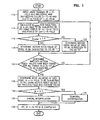
- FIG. 1 is a flow chart illustrating a conventional three-dimensional de-interlacing method.
- IPC is performed at a position (i, j) of an n-th field, as shown in FIG. 2.
- a pixel at the position (i, j) of the n-th field is referred to as Y n (i, j).
- image signals corresponding to the n-th field to be subjected to IPC and preceding and succeeding fields ((n-1)-th and (n+1)-th fields) of the n-th field are input in step 112. Subsequently, as shown in FIG. 2, a difference value D motion between the pixel of the (n-1)-th field and the pixel of the (n+1)-th field is calculated in step 114.
- the difference value D motion between the pixels can be determined from pixels Y n-1 (i, j) and Y n+1 (i, j) located at the preceding and succeeding positions of Y n (i, j) and the pixels Y n-1 (i, j ⁇ 1) and Y n+1 (i, j ⁇ 1) located at the horizontally left and right positions of the pixels Y n-1 (i, j) and Y n+1 (i, j), using the following Equation 1.
- the difference value D motion is compared with a predetermined threshold value T in step 116. If the difference value D motion is greater than the predetermined threshold value T, it is considered that the pixel Y n-1 (i, j) has moved and accordingly a motion index value M n (i, j) is determined as "1" in step 118. On the other hand, if the difference value D motion is smaller than the threshold value T, it is considered that the pixel Y n (i, j) has not moved and accordingly the motion index value M n (i, j) is determined as "0" in step 122.
- step 124 it is determined whether the motion pixel values have been found for all the pixels in the n-th field to be subjected to IPC.
- a mode value M is finally determined using a motion index value of a pixel in the n-th field, motion index values of the pixels at the horizontally left and right positions of the pixel, and two nearest motion index values to that of the pixel among motion index values of all pixels in the preceding field, in step 126. That is, as shown in FIG. 3, the mode value M of Y n (i, j) is calculated using Equation 2 below.
- step 1208 if the mode value M of Y n (i, j) is "0", it is determined that Y n (i, j) is in a stop mode. On the other hand, if the mode value M of Y n-1 (i, j) is not "0", it is determined that Y n-1 (i, j) is in a motion mode.
- a pixel value to which a temporal interpolation method using an average of two temporally adjacent pixels is applied is output in step 132.
- a pixel value to which a spatial interpolation method using an edge direction value is applied is output in step 134.
- the object of the present invention to provide a de-interlacing method and apparatus which can strongly determine a motion mode even in areas having no motion as well as in areas having motions by performing IPC using motion index values determined from two-dimensional low pass filtered pixel values.
- FIG. 4 is a block diagram showing a three-dimensional de-interlacing apparatus of the present invention.
- first and second frame memories 410 and 415 store an input image signal in units of a frame. That is, the first frame memory 410 stores a (n+1)-th field F n+1 and (n+2)-th field F n+2 of a current frame and the second frame memory 415 stores a (n-1)-th field F n-1 and n-th field F n of a previous frame. Accordingly, IPC is performed on the n-th field and (n+1)-th field using the image signals stored in the first frame memory 410 and second frame memory 415.
- a motion index value determination unit 420 performs two-dimensional low pass filtering on a pixel pm1 of a current frame and a pixel pm2 of the frame delayed by one frame from the current frame, obtains a difference value D motion of the filtered pixels cm1 and cm2, and compares the difference value D motion with a threshold value T to thereby determine motion index values of a current line in a field.
- a spatial interpolation unit 430 performs spatial interpolation of the pixels based on edge direction values detected at respective pixel positions in the n-th field F n and the (n+1)-th field F n+1 .
- a temporal interpolation unit 450 obtains an average value with respect to each pixel of the current frame and the corresponding pixel of the previous frame.
- a motion mode determination unit 460 determines a motion mode on each pixel using all the motion index values of the current pixel and peripheral pixels detected from the motion index value determination unit 420, and selects one between the output of the spatial interpolation unit 430 and the output of the temporal interpolation unit 450 on the basis of the motion mode. As a result, the motion mode determination unit 460 outputs the image signals of the n-th field F n and (n+1)-th field F n+1 subjected to IPC.
- FIG. 5 is a detailed view of the motion index value determination unit shown in FIG. 4.
- a first low-pass filter 510 performs two-dimensional low pass filtering on each pixel pm1 of the current frames F n+1 and F n+2 .
- a second low-pass filter 520 performs two-dimensional low pass filtering on the pixel pm2 of the previous frames F n-1 and F n at the spatially same position as each pixel pm1.
- the first and second low pass filters 510 and 520 output weighted averaging pixel values for respective pixels within predetermined areas.
- a difference calculation unit 530 obtains a difference value between the pixel value cm1 output from the first low pass filter 510 and the pixel value cm2 output from the second low pass filter 520.
- An absolute value calculation unit 540 obtains the absolute value of the difference value from the difference calculation unit 530.
- a motion index value determination unit 550 compares a difference value obtained from the absolute value calculation unit 540 with a threshold value to determine the motion index values of the respective pixels. That is, the motion index value determination unit 550 determines that a motion exists if the difference value is equal to and greater than the threshold value, and accordingly determines that a motion index value of the corresponding pixel is "1". On the other hand, the motion index value determination unit 550 determines that no motion exists if the difference value is smaller than the threshold value, and accordingly determines that the motion index value of the corresponding pixel is "0".
- FIG. 6 is a flow chart illustrating a three-dimensional de-interlacing method according to the present invention.
- F n (i, j) is defined as a pixel at a position (i, j) of an n-th field.
- image signals of current frames F n+1 and F n+2 and previous frames F n-1 and F n are input in step 612.
- IPC IPC of the n-th field F n .
- a pixel F n+1 (i, j) of two pixels at the temporally front and back positions of the pixel F n (i, j) to be subjected to IPC is assumed to be a first output pixel pm1 and a pixel F n-1 (i, j) of the frame delayed by one frame is assumed to be a second output pixel pm2.
- the first output pixel pm1 and second output pixel pm2 are used to generate the first filter output value cm1 and the second filter output value cm2, respectively, by the two-dimensional low pass filtering in step 614.
- the two-dimensional low pass filtering may be achieved by weighted averaging, that is, a method of obtaining an average by multiplying the pixels within a predetermined window area extended horizontally and vertically centering on the current pixel by a predetermined filter coefficient.
- Such low pass filtering is performed on the first output pixel pm1 and second output pixel pm2.
- the first filter output value cm1 is calculated using Equation 3 below.
- the second filter output value cm2 is calculated using Equation 4 below.
- ⁇ k,l is the filter coefficient within the predetermined area for the two-dimensional low pass filtering, for example, within a 3x3 area.
- the absolute value of the difference which will be referred to as D motion is obtained in step 616.
- the difference value D motion is compared with a threshold value T in step 618. If the difference value D motion is equal to and greater than the threshold value T, it is determined that the pixel F n (i, j) to be subjected to IPC is moved. Accordingly, a motion index value M(i, j) is determined as "1" in step 622. On the other hand, if the difference value D motion is smaller than the threshold value T, it is determined that the pixel F n (i, j) is not moved. Accordingly the motion index value M(i, j) is determined as "0" in step 624.
- step 616 the difference values D motion are obtained for all pixels in F n to be subjected to IPC and compared with the threshold value T to thereby obtain the motion index values. Subsequently, steps 614 through 626 are repeated for all the pixels in F n+1 to be subjected to IPC.
- a motion mode value M of each pixel in F n (i, j) to be subjected to IPC is determined using the motion index values of the field F n and peripheral fields thereof in step 628.
- IPC is performed on a bottom field of a first frame and a top field of a second frame in a pixel line sequence of the each field after reading the two adjacent frames.
- dark circles denote the pixels of the top field and white circles denote the pixels of the bottom field.
- the pixels of a vertical component are shown in a time direction.
- the fields to be subjected to IPC are the fields F n and F n+1 and the pixel to be presently subjected to IPC is the pixel at a dark square position (i, j) of the field F n .
- the motion mode value M of the pixel to be subjected to IPC is determined using the motion index value of the pixel and the motion index values at white square positions.
- all the motion index values of the past fields F n-2 and F n-1 are pre-stored in a particular storage.
- the motion mode values of an upper line of the line to be subjected to IPC are temporally pre-obtained values.
- the motion mode value M of F n (i, j) is represented using all of motion index values M n (i, j) and M n (i, j ⁇ 1) of the pixels in F n , motion index values (that is, M n+1 (i-1, j) and M n+1 (i-1, j ⁇ 1)) of the temporally and spatially nearest pixels to F n (i, j) among the pixels in F n+1 , motion index values (that is, M n-1 (i ⁇ 1, j) and M n-1 (i ⁇ 1, j ⁇ 1)) of the temporally and spatially nearest pixels to F n (i, j) among the pixels in F n-1 , and finally motion index values (that is, M n-2 (i, j) and M n-2 (i, j ⁇ 1)) of the temporally and spatially nearest pixels to F n (i, j) among the pixels in F n-2 , as the following Equation 5.
- the motion mode value M can be calculated using some among the 15 motion index values used in Equation 5 or using additional motion index values under some conditions.
- a pixel value to which a temporal interpolation method using an average value of two adjacent pixels is applied, is output in step 636.
- a pixel value to which a spatial interpolation method using edge direction values is applied is output in step 634.
- a method of performing a three-dimensional IPC on a UV component in a 4:2:0 YUV image signal is provided. That is, spatial interpolation and temporal interpolation are selectively used by detecting motions of the UV components of pixels as in Y components of pixels. However, because the UV components of pixels has a very small change, the motion mode determination using the motion index values of the pixels may generate an error. According to the present invention, the motion modes of the UV components of pixels are determined using the motion mode values obtained from the Y components of pixels.
- FIG. 8 shows the locations of the UV components of pixels in a 4:2:0 interlaced image. The parts denoted by circles represent the Y components, and the parts denoted by X represent the UV components.
- the motion mode value of a Y component at a position B is used instead of the motion mode value of the UV component at the position A. Because the mode value of the Y component is reliable and the distance between the positions A and B is also very small, the motion mode determination method of the present invention is useful. IPC of the UV components of pixels at other positions is also performed in the same manner. Accordingly, if the motion mode value of the UV component of a pixel to be subjected to IPC is "0", temporal interpolation is performed.
- the motion mode value is not "0"
- an average value of adjacent pixels above and below in a 90° direction is obtained.
- the UV components of pixels have a small motion, a directional interpolation as in the Y components of pixels is difficult. Also, because there are many possibilities that the direction of the Y component and the direction of the UV component are different to each other when trying to use a direction value of the Y component, a simple spatial interpolation having 90° direction is performed on the UV components of pixels.
- the present invention may be embodied in a general purpose digital computer by running a program from a computer readable medium, including but not limited to storage media such as magnetic storage media (e.g. ROM's, floppy disks, hard disks, etc.), optically readable media (e.g., CD-ROMs, DVDs, etc.) and carrier waves (e.g., transmissions over the Internet).
- the present invention may be embodied as a computer readable medium having a computer readable program code unit embodied therein for causing a number of computer system connected via a network to effect distributed processing.
Landscapes
- Engineering & Computer Science (AREA)
- Computer Graphics (AREA)
- Multimedia (AREA)
- Signal Processing (AREA)
- Television Systems (AREA)
Abstract
Description





Claims (10)
- A de-interlacing method of converting an interlaced format into a progressive format comprising:performing low pass filtering on respective predetermined pixels (Yn(i, j)) of a current frame (Fn+1) and previous frame (Fn-1);comparing a threshold value (T) to a difference value of the respective filtered pixels (cm1, cm2), and determining motion index values (Mn (i, j)) of respective pixels in a current field to be subjected to de-interlacing and of respective temporally and spatially adjacent pixels of the respective pixels;determining a motion mode (M) on the basis of the determined motion index values; andselectively performing spatial interpolation and temporal interpolation according to the determined motion mode (M).
- The de-interlacing method of claim 1, wherein the low pass filtering is performed by weighted averaging in which an average is obtained by multiplying a predetermined filter coefficient (ω) by pixels within a window having a predetermined vertical and horizontal size centering on respective pixels within one frame.
- The de-interlacing method of claim 1, wherein assuming that a field to be currently subjected to Interlaced-to-Progressive Conversion is an n-th field and a current pixel at a position (i, j) within the n-th field is Yn(i, j), a motion index value (Mn(i, j)) of the current pixel (Yn(i, j)) is determined as 1 if the difference value is equal to and greater than the threshold value (T), and the motion index value (Mn(i, j)) of the current pixel (Yn(i, j)) is determined as 0 if the difference value is less than the threshold value.
- The de-interlacing method of claim 1, wherein the motion mode value (M) of Yn(i, j) is determined bywherein Mn(i, j) is the motion index value of Yn(i, j).

- The de-interlacing method of claim 1, wherein if the sum of the motion index value (Mn (i, j)) of a pixel in the current field and the motion index values of temporally and spatially adjacent pixels of the pixel is "0", Yn(i, j) is in a stop mode, and if the sum is not "0", Yn(i, j) is in a motion mode.
- The de-interlacing method of claim 1, wherein a pixel value to which the temporal interpolation is applied is output if it is determined that the pixel value is in the stop mode and a pixel value to which the spatial interpolation is applied is output if it is determined that the pixel value is in the motion mode.
- The de-interlacing method of claim 1, further comprising:replacing the motion mode of a luminance component of pixel by the motion mode of a color difference component of pixel; andoutputting a pixel value of color difference component obtained by interpolating two adjacent pixels on a temporal axis if it is determined that the pixel value is in the stop mode, and outputting a pixel value of color difference component to which the pixels are spatially interpolated in a 90° direction if it is determined that the pixel value is in the motion mode.
- A de-interlacing apparatus of converting an interlaced format into a progressive format, the de-interlacing apparatus comprising:a spatial interpolation unit (430) which spatially interpolates along edge directions detected at respective pixel positions in a current frame;a temporal interpolation unit (450) which averages a pixel of the current frame (Fn+1) and a pixel of a previous frame (Fn-1);a motion index value determination unit (420) which performs two-dimensional low pass filtering on the pixel (pm1) of the current frame and a pixel (pm2) of a frame delayed by one frame from the current frame, obtains a difference value between the filtered pixel (cm1) of the current frame and the filtered pixel (cm2) of the delayed frame, and compares the difference value with a threshold value (T) to determine a motion index value of a pixel in a field; anda motion mode determination unit (460) which determines a motion mode (M) on the basis of motion index values (Mn(i,j)) of a pixel of a current field and adjacent pixels of a past field and future field detected by the motion index value determination unit (420), and selects the spatial interpolation unit and temporal interpolation unit according to the motion mode (M).
- The de-interlacing apparatus of claim 8, wherein the motion index value determination unit (420) includes:a first low pass filter (510) which performs the two-dimensional low pass filtering on the pixel on the current frame;a second low pass filter (520) which performs two-dimensional low pass filtering on the pixel of the frame delayed by one frame from the current frame;a difference calculation unit (530) which obtains a difference value between a pixel value output from the first (510) low pass filter and a pixel value output from the second low pass filter (520); anda motion index value determination unit (550) which compares the difference value calculated by the difference calculation unit (530) with the threshold value (T), and determines a motion index value (Mn(i,j)) of the pixel.
- The de-interlacing apparatus of claim 9, wherein the motion index value determination unit (550) determines a motion index value of the pixel as 1 if the difference value is equal to and greater than the threshold value (T), and determines the motion index value of the pixel as 0 if the difference value is smaller than the threshold value (T).
Applications Claiming Priority (2)
| Application Number | Priority Date | Filing Date | Title |
|---|---|---|---|
| KR2002087148 | 2002-12-30 | ||
| KR1020020087148A KR20040061244A (en) | 2002-12-30 | 2002-12-30 | Method and apparatus for de-interlacing viedo signal |
Publications (2)
| Publication Number | Publication Date |
|---|---|
| EP1441510A2 true EP1441510A2 (en) | 2004-07-28 |
| EP1441510A3 EP1441510A3 (en) | 2007-02-07 |
Family
ID=32588935
Family Applications (1)
| Application Number | Title | Priority Date | Filing Date |
|---|---|---|---|
| EP03014849A Withdrawn EP1441510A3 (en) | 2002-12-30 | 2003-06-30 | Method and apparatus for de-interlacing video signal |
Country Status (5)
| Country | Link |
|---|---|
| US (1) | US7265791B2 (en) |
| EP (1) | EP1441510A3 (en) |
| JP (1) | JP2004215263A (en) |
| KR (1) | KR20040061244A (en) |
| CN (1) | CN1266934C (en) |
Families Citing this family (48)
| Publication number | Priority date | Publication date | Assignee | Title |
|---|---|---|---|---|
| JP4003713B2 (en) * | 2003-08-06 | 2007-11-07 | ソニー株式会社 | Image processing apparatus and image processing method |
| US7345708B2 (en) * | 2003-12-23 | 2008-03-18 | Lsi Logic Corporation | Method and apparatus for video deinterlacing and format conversion |
| GB2411784B (en) * | 2004-03-02 | 2006-05-10 | Imagination Tech Ltd | Motion compensation deinterlacer protection |
| KR101127220B1 (en) * | 2004-07-28 | 2012-04-12 | 세종대학교산학협력단 | Apparatus for motion compensation-adaptive de-interlacing and method the same |
| US7405766B1 (en) * | 2004-12-20 | 2008-07-29 | Kolorific, Inc. | Method and apparatus for per-pixel motion adaptive de-interlacing of interlaced video fields |
| US7542095B2 (en) * | 2005-01-20 | 2009-06-02 | Samsung Electronics Co., Ltd. | Method and system of noise-adaptive motion detection in an interlaced video sequence |
| US7567294B2 (en) * | 2005-03-28 | 2009-07-28 | Intel Corporation | Gradient adaptive video de-interlacing |
| JP2006324979A (en) * | 2005-05-19 | 2006-11-30 | Fujitsu Ltd | Image still area determination device |
| US7982798B2 (en) * | 2005-09-08 | 2011-07-19 | Silicon Image, Inc. | Edge detection |
| US7787048B1 (en) * | 2005-09-08 | 2010-08-31 | Nvidia Corporation | Motion-adaptive video de-interlacer |
| US7619639B1 (en) * | 2005-09-12 | 2009-11-17 | Nvidia Corporation | Adaptive scaling using a programmable video engine |
| US7796191B1 (en) | 2005-09-21 | 2010-09-14 | Nvidia Corporation | Edge-preserving vertical interpolation |
| US20070097144A1 (en) * | 2005-10-27 | 2007-05-03 | Apple Computer, Inc. | Resampling individual fields of video information using a programmable graphics processing unit to provide improved full rate displays |
| CN100464580C (en) * | 2006-06-12 | 2009-02-25 | 北京中星微电子有限公司 | A motion detection and de-interlacing method and device for digital video processing |
| US7804542B2 (en) * | 2006-06-30 | 2010-09-28 | Intel Corporation | Spatio-temporal adaptive video de-interlacing for parallel processing |
| KR100813986B1 (en) | 2006-10-25 | 2008-03-14 | 삼성전자주식회사 | Motion adaptive deinterlacing method and apparatus therefor |
| JP4749314B2 (en) * | 2006-11-28 | 2011-08-17 | 富士通株式会社 | Interlace / progressive conversion method and conversion apparatus |
| GB2444534A (en) * | 2006-12-06 | 2008-06-11 | Sony Uk Ltd | Assessing the reliability of motion information in motion adaptive image processing |
| GB2444532A (en) * | 2006-12-06 | 2008-06-11 | Sony Uk Ltd | Motion adaptive image processing detecting motion at different levels of sensitivity |
| CN101197995B (en) * | 2006-12-07 | 2011-04-27 | 深圳艾科创新微电子有限公司 | Edge self-adapting de-interlacing interpolation method |
| JP2008182476A (en) * | 2007-01-24 | 2008-08-07 | Canon Inc | Change predicted value calculation apparatus and IP conversion processing apparatus |
| JP4891103B2 (en) * | 2007-01-25 | 2012-03-07 | キヤノン株式会社 | Motion amount detection apparatus, image processing apparatus using the same, and control method thereof |
| CN100479495C (en) * | 2007-02-09 | 2009-04-15 | 天津大学 | Deinterlacing method using motion detection and adaptive weighted filtering |
| US8031267B2 (en) * | 2007-02-12 | 2011-10-04 | Intel Corporation | Motion adaptive upsampling of chroma video signals |
| KR20090011407A (en) * | 2007-07-26 | 2009-02-02 | 삼성전자주식회사 | Image signal processing device and image signal processing method |
| KR100909032B1 (en) * | 2007-08-22 | 2009-07-23 | 주식회사 윈포넷 | Motion adaptive deinterlacing method and apparatus |
| JP4279332B2 (en) * | 2007-10-31 | 2009-06-17 | 株式会社東芝 | Progressive scan conversion apparatus and progressive scan conversion method |
| KR100936916B1 (en) * | 2007-12-14 | 2010-01-18 | 주식회사 윈포넷 | Deinterlacing apparatus and method |
| US20090268088A1 (en) * | 2008-04-25 | 2009-10-29 | Hui Zhou | Motion adaptive de-interlacer and method for use therewith |
| CN101588444B (en) * | 2008-05-20 | 2011-07-20 | 华为技术有限公司 | Interlacing removal method, interlacing removal device and video processing system for video data |
| JP4364287B1 (en) * | 2008-06-27 | 2009-11-11 | 株式会社東芝 | Video signal processing apparatus, television receiving apparatus, and control method therefor |
| KR100950226B1 (en) * | 2008-07-07 | 2010-03-29 | 한양대학교 산학협력단 | Image interpolation device and method and computer readable recording medium recording the method |
| JP2010088092A (en) * | 2008-09-02 | 2010-04-15 | Panasonic Corp | Three-dimensional video transmission system, video display device and video output device |
| US8559746B2 (en) * | 2008-09-04 | 2013-10-15 | Silicon Image, Inc. | System, method, and apparatus for smoothing of edges in images to remove irregularities |
| CN101600061B (en) * | 2009-07-09 | 2012-07-25 | 杭州士兰微电子股份有限公司 | Video motion-adaptive de-interlacing method and device therefor |
| JP5557311B2 (en) * | 2009-09-01 | 2014-07-23 | Necカシオモバイルコミュニケーションズ株式会社 | Video display device, display control method, and program |
| US8619123B2 (en) * | 2010-01-20 | 2013-12-31 | Kabushiki Kaisha Toshiba | Video processing apparatus and method for scaling three-dimensional video |
| TWI413023B (en) * | 2010-03-30 | 2013-10-21 | Novatek Microelectronics Corp | Method and apparatus for motion detection |
| US8692933B1 (en) * | 2011-10-20 | 2014-04-08 | Marvell International Ltd. | Method and apparatus for buffering anchor frames in motion compensation systems |
| US10979689B2 (en) * | 2014-07-16 | 2021-04-13 | Arris Enterprises Llc | Adaptive stereo scaling format switch for 3D video encoding |
| CN104702877A (en) * | 2014-12-02 | 2015-06-10 | 深圳市云宙多媒体技术有限公司 | Video de-interlacing method and device |
| CN104537606B (en) * | 2014-12-09 | 2018-02-02 | 中国农业大学 | Geographical coordinate projects changing method |
| CN104700360B (en) * | 2015-04-01 | 2018-06-05 | 北京思朗科技有限责任公司 | Image-scaling method and system based on edge self-adaption |
| CN105898177A (en) * | 2015-12-07 | 2016-08-24 | 乐视云计算有限公司 | De-interlacing method based on local information and device |
| CN105825282A (en) * | 2016-03-16 | 2016-08-03 | 上海翼锐汽车科技有限公司 | Cloud platform of charging piles |
| CN106127688B (en) * | 2016-06-30 | 2019-10-18 | 北京大学 | A super-resolution image reconstruction method and system thereof |
| CN107622447A (en) * | 2017-09-29 | 2018-01-23 | 瑧盈(北京)资产管理有限公司 | A kind of method and system for orienting commission product business |
| WO2021221188A1 (en) * | 2020-04-28 | 2021-11-04 | 엘지전자 주식회사 | Signal processing device and image display device including same |
Family Cites Families (20)
| Publication number | Priority date | Publication date | Assignee | Title |
|---|---|---|---|---|
| JPH0229178A (en) * | 1988-07-19 | 1990-01-31 | Sony Corp | Video signal processing circuit |
| KR970009469B1 (en) * | 1993-06-05 | 1997-06-13 | 삼성전자 주식회사 | Interlaced / sequential scan converter with double smoothing function and method |
| US5519451A (en) * | 1994-04-14 | 1996-05-21 | Texas Instruments Incorporated | Motion adaptive scan-rate conversion using directional edge interpolation |
| US5689305A (en) * | 1994-05-24 | 1997-11-18 | Kabushiki Kaisha Toshiba | System for deinterlacing digitally compressed video and method |
| US5521644A (en) * | 1994-06-30 | 1996-05-28 | Eastman Kodak Company | Mechanism for controllably deinterlacing sequential lines of video data field based upon pixel signals associated with four successive interlaced video fields |
| US5579054A (en) * | 1995-04-21 | 1996-11-26 | Eastman Kodak Company | System and method for creating high-quality stills from interlaced video |
| FR2742900B1 (en) * | 1995-12-22 | 1998-02-13 | Thomson Multimedia Sa | METHOD FOR INTERPOLATING PROGRESSIVE FRAMES |
| KR0183149B1 (en) * | 1995-12-30 | 1999-05-01 | 김광호 | Motion image detection method |
| KR0176568B1 (en) * | 1996-01-27 | 1999-05-01 | 김광호 | Device and method for conversion interlaced to progressive scanning |
| CN1096185C (en) | 1996-01-27 | 2002-12-11 | 三星电子株式会社 | Interlaced-to-progressive conversion apparatus and method using motion and spatial correlation |
| US6630961B1 (en) * | 1999-06-30 | 2003-10-07 | Lg Electronics Inc. | Deinterlacing device and method |
| JP2001054075A (en) * | 1999-08-06 | 2001-02-23 | Hitachi Ltd | Image signal motion compensation scan conversion circuit |
| US6459455B1 (en) * | 1999-08-31 | 2002-10-01 | Intel Corporation | Motion adaptive deinterlacing |
| KR100618792B1 (en) | 1999-11-04 | 2006-09-06 | 삼성전자주식회사 | Deinterlacing apparatus and method using four consecutive interlaced fields |
| US6414719B1 (en) * | 2000-05-26 | 2002-07-02 | Sarnoff Corporation | Motion adaptive median filter for interlace to progressive scan conversion |
| KR100708091B1 (en) * | 2000-06-13 | 2007-04-16 | 삼성전자주식회사 | Apparatus and method for frame rate conversion using bidirectional motion vector |
| US7095445B2 (en) * | 2000-12-20 | 2006-08-22 | Samsung Electronics Co., Ltd. | Method of detecting motion in an interlaced video sequence based on logical operation on linearly scaled motion information and motion detection apparatus |
| US6822691B1 (en) * | 2000-12-20 | 2004-11-23 | Samsung Electronics Co., Ltd. | Method of detecting motion in an interlaced video sequence utilizing region by region motion information and apparatus for motion detection |
| US6940557B2 (en) * | 2001-02-08 | 2005-09-06 | Micronas Semiconductors, Inc. | Adaptive interlace-to-progressive scan conversion algorithm |
| KR100393066B1 (en) * | 2001-06-11 | 2003-07-31 | 삼성전자주식회사 | Apparatus and method for adaptive motion compensated de-interlacing video data using adaptive compensated olation and method thereof |
-
2002
- 2002-12-30 KR KR1020020087148A patent/KR20040061244A/en not_active Ceased
-
2003
- 2003-06-30 CN CNB031484638A patent/CN1266934C/en not_active Expired - Fee Related
- 2003-06-30 EP EP03014849A patent/EP1441510A3/en not_active Withdrawn
- 2003-09-26 US US10/670,778 patent/US7265791B2/en not_active Expired - Fee Related
- 2003-12-25 JP JP2003431477A patent/JP2004215263A/en active Pending
Also Published As
| Publication number | Publication date |
|---|---|
| JP2004215263A (en) | 2004-07-29 |
| CN1266934C (en) | 2006-07-26 |
| US7265791B2 (en) | 2007-09-04 |
| US20040125231A1 (en) | 2004-07-01 |
| CN1512771A (en) | 2004-07-14 |
| EP1441510A3 (en) | 2007-02-07 |
| KR20040061244A (en) | 2004-07-07 |
Similar Documents
| Publication | Publication Date | Title |
|---|---|---|
| EP1441510A2 (en) | Method and apparatus for de-interlacing video signal | |
| US5784115A (en) | System and method for motion compensated de-interlacing of video frames | |
| US7379625B2 (en) | Edge direction based image interpolation method | |
| US6118488A (en) | Method and apparatus for adaptive edge-based scan line interpolation using 1-D pixel array motion detection | |
| US7206027B2 (en) | Spatial resolution of video images | |
| EP1313310A2 (en) | Method of low latency interlace to progressive video format conversion | |
| US8189105B2 (en) | Systems and methods of motion and edge adaptive processing including motion compensation features | |
| KR100739744B1 (en) | Method and System of Noise-adaptive Motion Detection in an Interlaced Video Sequence | |
| JP2002503428A (en) | A system for converting interlaced video to progressive video using edge correlation | |
| KR20020086536A (en) | Method for improving accuracy of block based motion compensation | |
| EP1039746B1 (en) | Line interpolation method and apparatus | |
| US20090219439A1 (en) | System and Method of Deinterlacing Interlaced Video Signals to Produce Progressive Video Signals | |
| KR100422575B1 (en) | An Efficient Spatial and Temporal Interpolation system for De-interlacing and its method | |
| JP4168490B2 (en) | Motion determination device, method and image information conversion device | |
| KR101509552B1 (en) | Method for generating distances representative of the edge orientations in a video picture, corresponding device and use of the method for deinterlacing or format conversion | |
| Tai et al. | A motion and edge adaptive deinterlacing algorithm | |
| JP2003179886A (en) | Image processing apparatus and method, recording medium, and program | |
| KR100874380B1 (en) | Deinterlacing apparatus and method using modified Sobel operator, and recording medium | |
| JP2005045700A (en) | Motion estimation method for moving picture interpolation and motion estimation apparatus for moving picture interpolation | |
| US20060033839A1 (en) | De-interlacing method | |
| EP1191785A1 (en) | Interlace to progresssive conversion | |
| JP3800638B2 (en) | Image information conversion apparatus and method | |
| KR100552685B1 (en) | Method and apparatus for converting interlaced image into sequential image | |
| JP4042121B2 (en) | Image information processing apparatus and image information processing method | |
| JP2003274371A (en) | Image processing apparatus and method, recording medium, and program |
Legal Events
| Date | Code | Title | Description |
|---|---|---|---|
| PUAI | Public reference made under article 153(3) epc to a published international application that has entered the european phase |
Free format text: ORIGINAL CODE: 0009012 |
|
| 17P | Request for examination filed |
Effective date: 20030630 |
|
| AK | Designated contracting states |
Kind code of ref document: A2 Designated state(s): AT BE BG CH CY CZ DE DK EE ES FI FR GB GR HU IE IT LI LU MC NL PT RO SE SI SK TR |
|
| AX | Request for extension of the european patent |
Extension state: AL LT LV MK |
|
| PUAL | Search report despatched |
Free format text: ORIGINAL CODE: 0009013 |
|
| AK | Designated contracting states |
Kind code of ref document: A3 Designated state(s): AT BE BG CH CY CZ DE DK EE ES FI FR GB GR HU IE IT LI LU MC NL PT RO SE SI SK TR |
|
| AX | Request for extension of the european patent |
Extension state: AL LT LV MK |
|
| AKX | Designation fees paid |
Designated state(s): DE FR GB |
|
| 17Q | First examination report despatched |
Effective date: 20071008 |
|
| STAA | Information on the status of an ep patent application or granted ep patent |
Free format text: STATUS: THE APPLICATION IS DEEMED TO BE WITHDRAWN |
|
| 18D | Application deemed to be withdrawn |
Effective date: 20091231 |