EP1441422A2 - A wear indicator - Google Patents
A wear indicator Download PDFInfo
- Publication number
- EP1441422A2 EP1441422A2 EP04250048A EP04250048A EP1441422A2 EP 1441422 A2 EP1441422 A2 EP 1441422A2 EP 04250048 A EP04250048 A EP 04250048A EP 04250048 A EP04250048 A EP 04250048A EP 1441422 A2 EP1441422 A2 EP 1441422A2
- Authority
- EP
- European Patent Office
- Prior art keywords
- carbon brush
- wear indicator
- arced
- housing
- contact portion
- Prior art date
- Legal status (The legal status is an assumption and is not a legal conclusion. Google has not performed a legal analysis and makes no representation as to the accuracy of the status listed.)
- Withdrawn
Links
Images



Classifications
-
- H—ELECTRICITY
- H01—ELECTRIC ELEMENTS
- H01R—ELECTRICALLY-CONDUCTIVE CONNECTIONS; STRUCTURAL ASSOCIATIONS OF A PLURALITY OF MUTUALLY-INSULATED ELECTRICAL CONNECTING ELEMENTS; COUPLING DEVICES; CURRENT COLLECTORS
- H01R39/00—Rotary current collectors, distributors or interrupters
- H01R39/02—Details for dynamo electric machines
- H01R39/58—Means structurally associated with the current collector for indicating condition thereof, e.g. for indicating brush wear
Definitions
- the present invention relates to a wear indicator for a motor carbon brush and to a commutator motor comprising one or more of the wear indicators.
- a conventional commutator motor includes a housing, a carbon brush which is slidably mounted within the housing and at least one alarm indicator light. An end of the carbon brush bears against an elastic element and the other end contacts the round surface of the commutator. The carbon brush is biased against the commutator by means of the elastic element. A wire is embedded in the carbon brush in order to detect the wear degree to ensure that the carbon brush is timely replaced. When the carbon brush is worn and slides to a predetermined position, the wire is exposed and turns the alarm indicator light on. Generally such a carbon brush with an embedded wire is complicated to manufacture.
- Another conventional arrangement incorporates an opening at a predetermined position of the carbon brush.
- a lighting element is disposed on one side of the carbon brush and a receiving element on the other side.
- the receiving element receives through the opening the light emitted by the lighting element and turns the alarm indicator light on.
- a disadvantage of this arrangement is that the opening may become blocked ( eg by dust) which interrupts the light making the alarm ineffective.
- the present invention seeks to provide a simple and reliable wear indicator for a motor carbon brush.
- the present invention provides a wear indicator for a motor carbon brush including:
- the present invention relates to a wear indicator for a motor carbon brush comprising: a housing and a carbon brush which is slidably mounted within the housing.
- An elastic element is positioned on the housing and is biased against the rear end of the carbon brush.
- a circuit board with an alarm indicator light is fixed to the housing.
- a front end portion of the carbon brush contacts the round surface of the commutator.
- the circuit board is equipped with an electric probe which is electrically connected to the alarm indicator light.
- the carbon brush surface has a contact portion such that when the carbon brush is in the first operational state, the surface ( eg end) of the electric probe is disconnected from the contact portion on the carbon brush and the circuit which is made up of the carbon brush, electric probe and alarm indicator light in series is incomplete so that the alarm indicator light is switched off.
- the surface ( eg end) of the electric probe contacts the contact portion on the carbon brush and the circuit which is made up of the carbon brush, electric probe and alarm indicator light in series is complete so that the alarm indicator light is turned on.
- the present invention exploits the conductive character of the carbon brush by providing a continuously exposed contact portion on the carbon brush to which the alarm indicator light may be electrically connected through an electric probe. When the brush is worn and needs to be changed, the electrical connection is made and the alarm indicator light is turned on.
- the present invention is reliable and simple to manufacture.
- the contact portion (and/or the surface of the electric probe which it contacts) is arced.
- the contact portion is continuously exposed.
- the circuit board is a substantially planar body and the electric probe takes the form of a substantially columnar or angular projection from the planar body, wherein the substantially columnar or angular projection and the contact portion are capable of relative movement from the first operational state to the second operational state.
- the substantially columnar or angular projection is static and the carbon brush moves between the first and second operational state as it wears.
- the position of the carbon brush in the second operational state can be predetermined to coincide with a position in which the carbon brush is worn to a degree which requires its replacement.
- the wear indicator further comprises: an elongate truncated slot disposed on the surface of the carbon brush, wherein the contact portion is disposed at the end of the elongate truncated slot ( eg the end wall).
- the carbon brush is slidably mounted within the housing in a sliding direction and the wear indicator further comprises: an elongate truncated slot disposed on the surface of the carbon brush which extends co-directionally with the sliding direction, wherein the contact portion is an end portion of the elongate truncated slot ( eg the end wall) and the electric probe takes the form of an angular projection from the planar body whose end is inserted freely into the elongate truncated slot.
- the angular projection has an arced end surface opposing the end portion, wherein in use when the carbon brush is in the second operational state, the arced end surface contacts the end portion of the elongate truncated slot.
- the end portion of the elongate truncated slot is arced.
- the angular projection may take any suitable form.
- the angular projection may be comprise a main body from which is angularly dependent an arm which extends into the elongate truncated slot.
- the main body may project from the planar body be twin legs.
- the housing will typically have an elongate slot coincident with the elongate truncated slot in the carbon brush.
- the contact portion is a protrusion protruding from the surface of the carbon brush.
- the carbon brush is slidably mounted within the housing in a sliding direction and the wear indicator further comprises: a guiding slot in the housing which extends co-directionally with the sliding direction, wherein the protrusion protrudes through the guiding slot and wherein the electric probe takes the form of a substantially columnar projection from the planar body.
- the substantially columnar projection has an arced surface opposing a contact surface of the protrusion wherein in use when the carbon brush is in the second operational state, the arced surface contacts the contact surface of the protrusion.
- the contact surface of the protrusion is arced.
- the contact portion is an electrically conductive protrusion protruding from the surface of the carbon brush whose root is embedded in the carbon brush.
- the carbon brush is slidably mounted within the housing in a sliding direction and the wear indicator further comprises: a guiding slot in the housing which extends co-directionally with the sliding direction, wherein the electrically conductive protrusion protrudes through the guiding slot and wherein the electric probe takes the form of a substantially columnar projection from the planar body.
- the substantially columnar projection has an arced surface opposing a contact surface of the electrically conductive protrusion wherein in use when the carbon brush is in the second operational state, the arced surface contacts the contact surface of the electrically conductive protrusion.
- the contact surface of the electrically conductive protrusion is arced.
- the present invention provides a commutator motor comprising one or more wear indicators as defined hereinbefore.
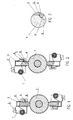
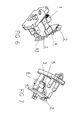
- FIGS 1-9 illustrate a wear indicator for a carbon brush including a housing 3 and a carbon brush 4 which is slidably mounted within the housing 3.
- a torsion spring 1 is positioned on the housing 3 and bears against the rear end of the carbon brush 4.
- the front end of the carbon brush 4 touches the round surface of a commutator 7 and the surface of the carbon brush 4 has a contact portion.
- a planar circuit board 13 which is equipped with an alarm indicator light 2 is fixed to the housing 3.
- On the circuit board 13 is disposed an electric probe 5 which is electrically connected to the alarm indicator light 2.
- an end surface of the electric probe 5 is disconnected from the contact portion.
- the end surface of the electric probe 5 touches the contact portion of the carbon brush 4.
- an elongate truncated slot 6 is disposed on the surface of the carbon brush 4 which extends in the sliding direction of the carbon brush 4.
- the electric probe 5 takes the form of an angular projection freely insertable into the elongate truncated slot 6.
- the contact portion is an end wall 9 of the elongate truncated slot 6 which is arced (see Figure 3).
- the electric probe 5 has an arced end surface 8 opposing the arced end wall 9 ( ie an end surface 8 arced in a direction opposite to the direction of travel of the carbon brush).
- the arced end surface 8 slides freely in the slot and the alarm indicator remains unlit.
- the arced end surface 8 touches the arced end wall 9 of the carbon brush 4 (see Figure 3) and the alarm indicator light 2 is switched on.
- the slot 6 is truncated ( ie the end of the carbon brush 4 is remote from the arced end wall 9 of the slot 6) by a predetermined distance.
- the carbon brush 4 need not be displaced immediately and in fact may be used continually for a short period of time ( eg an hour) without burning the motor.
- the contact portion of the carbon brush 4 is an electrically conductive protrusion 10 made from an electrically conductive material such as a metal which protrudes from the surface of the carbon brush 4 and the housing 3.
- the root of the electrically conductive protrusion 10 is embedded in the carbon brush 4.
- the electrically conductive protrusion 10 follows the movement of the carbon brush 4 along a guiding slot 11.
- An electric probe 5 protrudes from the circuit board 13.
- the electrically conductive protrusion 10 contacts the electric probe 5 when the carbon brush 4 has moved a predetermined distance.
- the end face of the electrically conductive protrusion 10 and the surface of the electric probe 5 which contact each other are arced.
- the contact portion of the carbon brush 4 is a protrusion 12 integrally formed on the carbon brush 4 which protrudes from the surface of the carbon brush 4 and the housing 3.
- the protrusion 12 follows the movement of the carbon brush 4 along a guiding slot 11.
- An electric probe 5 protrudes from the circuit board 13.
- the protrusion 12 contacts the electric probe 5 when the carbon brush 4 has moved a predetermined distance.
- the end face of the protrusion 12 and the surface of the electric probe 5 which contact each other are arced.
Landscapes
- Motor Or Generator Current Collectors (AREA)
Abstract
Description
Claims (17)
- A wear indicator for a motor carbon brush including:wherein in use when the carbon brush [4] is in a first operational state, a surface of the electric probe [5] is disconnected from the contact portion of the carbon brush [4] and when the carbon brush [4] is in a second operational state, the surface of the electric probe [5] touches the contact portion of the carbon brush [4].a housing [3];a carbon brush [4] slidably mounted within the housing [3], wherein the front end of the carbon brush [4] touches the surface of the commutator [7] and the surface of the carbon brush [4] has a contact portion;an elastic element positioned on the housing [3] which bears against the rear end of the carbon brush [4];a circuit board [13] which is equipped with an alarm indicator light [2] and is fixed to the housing [3];an electric probe [5] disposed on the circuit board [13] which is electrically connected to the alarm indicator light [2],
- A wear indicator as claimed in claim 1 wherein the circuit board [13] is a substantially planar body and the electric probe [5] takes the form of a substantially columnar or angular projection from the planar body, wherein the substantially columnar or angular projection and the contact portion [9] are capable of relative movement from the first operational state to the second operational state.
- A wear indicator as claimed in claim 1 or 2 further comprising: an elongate truncated slot [6] disposed on the surface of the carbon brush [4] wherein the contact portion is disposed at the end of the elongate truncated slot [6].
- A wear indicator as claimed in claim 2 wherein the carbon brush [4] is slidably mounted within the housing [3] in a sliding direction and and the wear indicator further comprises:an elongate truncated slot [6] disposed on the surface of the carbon brush [4] which extends co-directionally with the sliding direction, wherein the contact portion is an end portion [9] of the elongate truncated slot [6] and the electric probe [5] takes the form of an angular projection from the planar body whose end is inserted freely into the elongate truncated slot [6].
- A wear indicator as claimed in claim 4, wherein the angular projection has an arced end surface [8] opposing the end portion [9], wherein in use when the carbon brush [4] is in the second operational state, the arced end surface [8] contacts the end portion [9] of the elongate truncated slot [6].
- A wear indicator as claimed in claim 5, wherein the end portion [9] of the elongate truncated slot [6] is arced.
- A wear indicator as claimed in claim 1 or 2, wherein the contact portion is a protrusion [12] protruding from the surface of the carbon brush [4].
- A wear indicator as claimed in claim 7 wherein the carbon brush [4] is slidably mounted within the housing [3] in a sliding direction and the wear indicator further comprises:a guiding slot [11] in the housing [3] which extends co-directionally with the sliding direction, wherein the protrusion [12] protrudes through the guiding slot [11] and wherein the electric probe [5] takes the form of a substantially columnar projection from the planar body.
- A wear indicator as claimed in claim 8, wherein the substantially columnar projection has an arced surface opposing a contact surface of the protrusion [12] wherein in use when the carbon brush [4] is in the second operational state, the arced surface contacts the contact surface of the protrusion [12].
- A wear indicator as claimed in claim 9, wherein the contact surface of the protrusion [12] is arced.
- A wear indicator as claimed in claim 1 or 2, wherein the contact portion is an electrically conductive protrusion [10] protruding from the surface of the carbon brush [4] whose root is embedded in the carbon brush [4].
- A wear indicator as claimed in claim 11 wherein the carbon brush [4] is slidably mounted within the housing [3] in a sliding direction and the wear indicator further comprises:a guiding slot [11] in the housing [3] which extends co-directionally with the sliding direction, wherein the electrically conductive protrusion [10] protrudes through the guiding slot [11] and wherein the electric probe [5] takes the form of a substantially columnar projection from the planar body.
- A wear indicator as claimed in claim 12, wherein the substantially columnar projection has an arced surface opposing a contact surface of the electrically conductive protrusion [10] wherein in use when the carbon brush [4] is in the second operational state, the arced surface contacts the contact surface of the electrically conductive protrusion [10].
- A wear indicator as claimed in claim 13, wherein the contact surface of the electrically conductive protrusion [10] is arced.
- A wear indicator as claimed in claim 1 wherein the contact portion is continuously exposed.
- A wear indicator as claimed in claim 1 wherein the contact portion and/or the surface of the electric probe is arced.
- A commutator motor comprising one or more wear indicators as defined in any preceding claim.
Applications Claiming Priority (2)
| Application Number | Priority Date | Filing Date | Title |
|---|---|---|---|
| CNB031127002A CN100350682C (en) | 2003-01-14 | 2003-01-14 | Carbon brush wear sensor device of motor |
| CN03112700 | 2003-01-14 |
Publications (2)
| Publication Number | Publication Date |
|---|---|
| EP1441422A2 true EP1441422A2 (en) | 2004-07-28 |
| EP1441422A3 EP1441422A3 (en) | 2006-07-12 |
Family
ID=32514463
Family Applications (1)
| Application Number | Title | Priority Date | Filing Date |
|---|---|---|---|
| EP04250048A Withdrawn EP1441422A3 (en) | 2003-01-14 | 2004-01-07 | A wear indicator |
Country Status (3)
| Country | Link |
|---|---|
| US (1) | US6933650B2 (en) |
| EP (1) | EP1441422A3 (en) |
| CN (1) | CN100350682C (en) |
Cited By (7)
| Publication number | Priority date | Publication date | Assignee | Title |
|---|---|---|---|---|
| WO2014150190A1 (en) * | 2013-03-14 | 2014-09-25 | Cutsforth, Inc. | System and method for monitoring the status of one or more components of an electrical machine |
| EP2429045A3 (en) * | 2010-09-09 | 2014-10-08 | Robert Bosch GmbH | Device and method for wear monitoring of a brush of a commuter system in an electric machine |
| US10348047B2 (en) | 2015-06-01 | 2019-07-09 | Cutsforth, Inc. | Brush wear and vibration monitoring |
| US10371726B2 (en) | 2016-01-11 | 2019-08-06 | Cutsforth, Inc. | Monitoring system for grounding apparatus |
| US11211757B2 (en) | 2018-10-04 | 2021-12-28 | Cutsforth, Inc. | System and method for monitoring the status of one or more components of an electrical machine |
| US11355991B2 (en) | 2018-10-04 | 2022-06-07 | Cutsforth, Inc. | System and method for monitoring the status of one or more components of an electrical machine |
| US11566675B2 (en) | 2018-03-21 | 2023-01-31 | Ab Dynamoborstfabriken | Intelligent graphite device |
Families Citing this family (20)
| Publication number | Priority date | Publication date | Assignee | Title |
|---|---|---|---|---|
| US7610477B2 (en) * | 2004-09-15 | 2009-10-27 | Microsoft Corporation | Deploying and receiving software over a network susceptible to malicious communication |
| CN100456572C (en) * | 2004-11-19 | 2009-01-28 | 乐金电子(天津)电器有限公司 | Commutator structure for single-phase series motor |
| US8624464B2 (en) * | 2005-05-20 | 2014-01-07 | Schlumberger Technology Corporation | Brush and brush housing arrangement to mitigate hydrodynamic brush lift in fluid-immersed electric motors |
| US7705744B2 (en) * | 2007-05-24 | 2010-04-27 | Cutsforth Products, Inc. | Monitoring systems and methods for monitoring the condition of one or more components of an electrical device |
| US8618943B2 (en) | 2007-05-24 | 2013-12-31 | Cutsforth, Inc. | Brush holder assembly monitoring apparatus, assembly, system and method |
| US7969059B2 (en) * | 2008-02-20 | 2011-06-28 | Bodine Electric Company | Brush assembly having a brush wear detector and indicator for a D.C. motor |
| US7880362B2 (en) * | 2008-03-14 | 2011-02-01 | Cutsforth Products, Inc. | Brush holder assembly with spring clip |
| EP2112518A1 (en) * | 2008-04-25 | 2009-10-28 | ALSTOM Technology Ltd | Brush wear monitor |
| KR100970338B1 (en) * | 2008-11-07 | 2010-07-15 | 진기호 | Starter replacement warning device for automobile |
| US8384266B2 (en) * | 2011-03-29 | 2013-02-26 | General Electric Company | Brush wear detector system with wireless sensor |
| CN102522854A (en) * | 2011-12-28 | 2012-06-27 | 大连宜顺机电有限公司 | Slip ring brush holder system brush alarm device |
| CN103368032B (en) * | 2013-07-19 | 2016-02-10 | 江苏华宇碳素有限公司 | Carbon brush holder |
| CN104049244B (en) * | 2014-06-23 | 2017-01-04 | 中国人民解放军63698部队 | The radar velocity measurement machine carbon brush abrasion recognition methods analyzed based on temporal signatures value |
| US10079463B2 (en) * | 2015-11-19 | 2018-09-18 | Borgwarner Inc. | Brush wear indicator |
| CN106887783A (en) * | 2017-03-08 | 2017-06-23 | 深圳市晶沛电子有限公司 | A kind of conducting slip ring |
| CN107658667B (en) * | 2017-10-12 | 2023-12-12 | 上海源盛机械电气制造有限公司 | Slip ring carbon brush with wear monitoring function |
| CN108462018B (en) * | 2018-04-26 | 2024-01-30 | 大同新成新材料股份有限公司 | Abrasion sensing device of carbon brush assembly of graphene carbon motor and application method of abrasion sensing device |
| US11279086B2 (en) * | 2019-07-15 | 2022-03-22 | Hamilton Sundstrand Corporation | Soft recoater blade and method of detecting wear |
| CN111490426A (en) * | 2020-04-17 | 2020-08-04 | 唐山钢铁集团有限责任公司 | Visual early warning device of motor carbon brush wearing and tearing |
| CN112071035A (en) * | 2020-09-30 | 2020-12-11 | 保定承宇节能环保科技有限公司 | Motor carbon brush alarm device |
Family Cites Families (10)
| Publication number | Priority date | Publication date | Assignee | Title |
|---|---|---|---|---|
| US3924147A (en) * | 1974-01-02 | 1975-12-02 | Barber Colman Co | Brushholders and ancillary components mounted on a printed circuit board |
| US4024525A (en) * | 1976-01-07 | 1977-05-17 | Towmotor Corporation | Brush wear indicator |
| GB1541997A (en) * | 1977-08-02 | 1979-03-14 | Towmotor Corp | Brush wear indicating means |
| US4344009A (en) * | 1980-09-04 | 1982-08-10 | General Electric Co. | Brush wear indicator for a dynamoelectric machine brush |
| JPS57170044A (en) * | 1981-04-10 | 1982-10-20 | Hitachi Ltd | Brush wear limit detector |
| JPS589552A (en) * | 1981-07-10 | 1983-01-19 | Fuji Xerox Co Ltd | Display device for abrasion of brush |
| JPS61142943A (en) * | 1984-12-14 | 1986-06-30 | Toshiba Corp | Abrasion meter for rotary machine brush |
| US4950933A (en) * | 1989-08-03 | 1990-08-21 | Westinghouse Electric Corp. | Carbon brush holder utilizing a worn brush detector |
| US5509625A (en) * | 1993-12-21 | 1996-04-23 | United Technologies Corp. | Electrical brush-wear indicator |
| JPH10257735A (en) * | 1997-03-11 | 1998-09-25 | Matsushita Electric Ind Co Ltd | Commutator electric blower |
-
2003
- 2003-01-14 CN CNB031127002A patent/CN100350682C/en not_active Expired - Fee Related
-
2004
- 2004-01-07 EP EP04250048A patent/EP1441422A3/en not_active Withdrawn
- 2004-01-09 US US10/754,274 patent/US6933650B2/en not_active Expired - Fee Related
Cited By (17)
| Publication number | Priority date | Publication date | Assignee | Title |
|---|---|---|---|---|
| EP2429045A3 (en) * | 2010-09-09 | 2014-10-08 | Robert Bosch GmbH | Device and method for wear monitoring of a brush of a commuter system in an electric machine |
| USRE48756E1 (en) | 2013-03-14 | 2021-09-28 | Cutsforth, Inc. | System and method for monitoring the status of one or more components of an electrical machine |
| US9252643B2 (en) | 2013-03-14 | 2016-02-02 | Cutsforth, Inc. | System and method for monitoring the status of one or more components of an electrical machine |
| US9640930B2 (en) | 2013-03-14 | 2017-05-02 | Cutsforth, Inc. | System and method for monitoring the status of one or more components of an electrical machine |
| WO2014150190A1 (en) * | 2013-03-14 | 2014-09-25 | Cutsforth, Inc. | System and method for monitoring the status of one or more components of an electrical machine |
| US10348047B2 (en) | 2015-06-01 | 2019-07-09 | Cutsforth, Inc. | Brush wear and vibration monitoring |
| US11050205B2 (en) | 2015-06-01 | 2021-06-29 | Cutsforth, Inc. | Brush wear and vibration monitoring |
| US10649011B2 (en) | 2016-01-11 | 2020-05-12 | Cutsforth, Inc. | Monitoring system for grounding apparatus |
| US10371726B2 (en) | 2016-01-11 | 2019-08-06 | Cutsforth, Inc. | Monitoring system for grounding apparatus |
| US11566675B2 (en) | 2018-03-21 | 2023-01-31 | Ab Dynamoborstfabriken | Intelligent graphite device |
| US11211757B2 (en) | 2018-10-04 | 2021-12-28 | Cutsforth, Inc. | System and method for monitoring the status of one or more components of an electrical machine |
| US11355991B2 (en) | 2018-10-04 | 2022-06-07 | Cutsforth, Inc. | System and method for monitoring the status of one or more components of an electrical machine |
| US11616413B2 (en) | 2018-10-04 | 2023-03-28 | Cutsforth, Inc. | System and method for monitoring the status of one or more components of an electrical machine |
| US11949314B2 (en) | 2018-10-04 | 2024-04-02 | Cutsforth, Inc. | System and method for monitoring the status of one or more components of an electrical machine |
| US12003067B2 (en) | 2018-10-04 | 2024-06-04 | Cutsforth, Inc. | System and method for monitoring the status of one or more components of an electrical machine |
| US12212210B2 (en) | 2018-10-04 | 2025-01-28 | Cutsforth, Inc. | System and method for monitoring the status of one or more components of an electrical machine |
| US12418151B2 (en) | 2018-10-04 | 2025-09-16 | Cutsforth, Inc. | System and method for monitoring the status of one or more components of an electrical machine |
Also Published As
| Publication number | Publication date |
|---|---|
| CN100350682C (en) | 2007-11-21 |
| CN1518174A (en) | 2004-08-04 |
| EP1441422A3 (en) | 2006-07-12 |
| US6933650B2 (en) | 2005-08-23 |
| US20040155553A1 (en) | 2004-08-12 |
Similar Documents
| Publication | Publication Date | Title |
|---|---|---|
| US6933650B2 (en) | Wear indicator | |
| US6733146B1 (en) | Illuminated knob for indicating the operative condition of an appliance | |
| CN110013337B (en) | electric toothbrush | |
| US7045929B2 (en) | Wear-premonitory carbon brush holder | |
| JPH09182384A (en) | Motor brush abrasion informing device | |
| US7536801B2 (en) | Laser leveling device | |
| JP4976180B2 (en) | Rotating electrical parts | |
| WO2009125838A1 (en) | Plug and tap | |
| US3280321A (en) | Door handle light for automobiles | |
| GB2168850A (en) | Key switch | |
| CN117374673A (en) | Power rail adapter | |
| WO2002035566A3 (en) | Rotary trip switch | |
| KR100592867B1 (en) | Multi-Purpose Electrical Plugs and Plug Adapters | |
| ES3053588T3 (en) | Aerosol generation device with flexible cover | |
| CN112296917B (en) | An electrician's tool | |
| JP4522194B2 (en) | Electric tool | |
| KR890002554Y1 (en) | Motor brush support | |
| KR200235471Y1 (en) | Safety Electric Outlet | |
| CN222752541U (en) | Multi-directional input detection device | |
| CN214174493U (en) | Test pencil | |
| CN219085848U (en) | Electric tool switch with magnet quenching and arcing functions | |
| CN222508861U (en) | Flashlight charging box and lighting assembly | |
| CN214037994U (en) | Magnetic line lamp | |
| CN223462551U (en) | Socket with auxiliary device and protection door | |
| KR200340570Y1 (en) | LED direct connected rotary switch |
Legal Events
| Date | Code | Title | Description |
|---|---|---|---|
| PUAI | Public reference made under article 153(3) epc to a published international application that has entered the european phase |
Free format text: ORIGINAL CODE: 0009012 |
|
| AK | Designated contracting states |
Kind code of ref document: A2 Designated state(s): AT BE BG CH CY CZ DE DK EE ES FI FR GB GR HU IE IT LI LU MC NL PT RO SE SI SK TR |
|
| AX | Request for extension of the european patent |
Extension state: AL LT LV MK |
|
| PUAL | Search report despatched |
Free format text: ORIGINAL CODE: 0009013 |
|
| AK | Designated contracting states |
Kind code of ref document: A3 Designated state(s): AT BE BG CH CY CZ DE DK EE ES FI FR GB GR HU IE IT LI LU MC NL PT RO SE SI SK TR |
|
| AX | Request for extension of the european patent |
Extension state: AL LT LV MK |
|
| STAA | Information on the status of an ep patent application or granted ep patent |
Free format text: STATUS: THE APPLICATION IS DEEMED TO BE WITHDRAWN |
|
| 18D | Application deemed to be withdrawn |
Effective date: 20060801 |