EP1441347A1 - Disc drive - Google Patents
Disc drive Download PDFInfo
- Publication number
- EP1441347A1 EP1441347A1 EP01978893A EP01978893A EP1441347A1 EP 1441347 A1 EP1441347 A1 EP 1441347A1 EP 01978893 A EP01978893 A EP 01978893A EP 01978893 A EP01978893 A EP 01978893A EP 1441347 A1 EP1441347 A1 EP 1441347A1
- Authority
- EP
- European Patent Office
- Prior art keywords
- feed screw
- screw axis
- height
- height control
- movable portion
- Prior art date
- Legal status (The legal status is an assumption and is not a legal conclusion. Google has not performed a legal analysis and makes no representation as to the accuracy of the status listed.)
- Granted
Links
Images




Classifications
-
- G—PHYSICS
- G11—INFORMATION STORAGE
- G11B—INFORMATION STORAGE BASED ON RELATIVE MOVEMENT BETWEEN RECORD CARRIER AND TRANSDUCER
- G11B7/00—Recording or reproducing by optical means, e.g. recording using a thermal beam of optical radiation by modifying optical properties or the physical structure, reproducing using an optical beam at lower power by sensing optical properties; Record carriers therefor
- G11B7/08—Disposition or mounting of heads or light sources relatively to record carriers
-
- G—PHYSICS
- G11—INFORMATION STORAGE
- G11B—INFORMATION STORAGE BASED ON RELATIVE MOVEMENT BETWEEN RECORD CARRIER AND TRANSDUCER
- G11B7/00—Recording or reproducing by optical means, e.g. recording using a thermal beam of optical radiation by modifying optical properties or the physical structure, reproducing using an optical beam at lower power by sensing optical properties; Record carriers therefor
-
- G—PHYSICS
- G11—INFORMATION STORAGE
- G11B—INFORMATION STORAGE BASED ON RELATIVE MOVEMENT BETWEEN RECORD CARRIER AND TRANSDUCER
- G11B7/00—Recording or reproducing by optical means, e.g. recording using a thermal beam of optical radiation by modifying optical properties or the physical structure, reproducing using an optical beam at lower power by sensing optical properties; Record carriers therefor
- G11B7/08—Disposition or mounting of heads or light sources relatively to record carriers
- G11B7/085—Disposition or mounting of heads or light sources relatively to record carriers with provision for moving the light beam into, or out of, its operative position or across tracks, otherwise than during the transducing operation, e.g. for adjustment or preliminary positioning or track change or selection
- G11B7/0857—Arrangements for mechanically moving the whole head
- G11B7/08582—Sled-type positioners
Definitions
- the present invention relates to a disk device in which an angle adjustment of feed screw axis in relation to a base, can be performed.
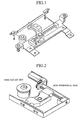
- a disk device in which whole driving unit is performed a height control in relation to a base as shown in Fig. 1 in order not to lose a driving force which is transferred from a driving source to a feed screw axis by performing the height control when an angle adjustment of feed screw axis in relation to the base is performed by a control of attaching height in relation to the base for an end portion of the feed screw (hereinafter refereed to as first prior art).
- the controlled movable portion can be made smaller on which the height control is performed, however, it causes a necessity that the driving means must be located on the other side of a height control performed side, and basically one end is fixed and other end is performed the height control to perform the angle adjustment.
- the height control is performed at an end portion of the disk peripheral side. Because the driving means must be arranged at a center side of the disk, a space to arrange the driving means is required at the vicinity of a disk motor.
- the height control can be performed only at one end portion of the device, though the angle adjustment of feed screw axis in relation to the base can be performed, the height control at both ends cannot be achieved and thereby it causes a problem that even when the height control for whole screw axis in relation to the base is required in conjunction with the angle adjustment, it cannot be achieved.
- a shaft bearing member at the height control side is composed of one shaft bearing block, and it is guided enably to be performed the height control by a shaft bearing sliding block which is fixed on the base, because this guide is structured by an interlocking of these two, when a clearance between them is large by a fluctuation in tolerance of parts, it causes a problem that a positioning of the shaft bearing block becomes unstable when the shaft bearing block rattles also in a direction other than the height control in relation to the shaft bearing sliding block.
- the present invention has been made to solve the above described problems and it is an object of the invention to provide a disk device in which the feed screw axis can be accurately positioned as well as the angle adjustment of feed screw axis in relation to a base and the height control of whole feed screw axis, can be performed without having scaling up of whole mechanism and without reducing a degree of freedom in designing.
- the disk device in accordance with the present invention includes a movable portion to support pivotally and enably to swing a feed screw axis; a driving means for the feed screw axis to be rotated by driving a gear which engages with a gear interlocked at an end portion of height control side of the feed screw axis; and a control means to control a height of the movable portion.
- the disk device in accordance with the present invention includes a shaft center of gear which is arranged such that it is located in the same height of a middle point in a range of the height control by the height control means and it is located on a line perpendicular to a direction of the height control by the height control means.
- the disk device in accordance with the present invention includes a holding portion which is fixed on the base to support the movable portion in the height direction and at the same time to regulate a positioning of the feed screw axis in a direction perpendicular to the axial direction and a height direction.
- the disk device in accordance with the present invention includes a swinging axis which is arranged on the movable portion for the movable portion to swing around an axis parallel to an axial direction of the feed screw axis and to support the swinging axis enably to swing.
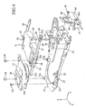
- Fig. 3 is a perspective view to show whole optical head driving mechanism including a feed screw axis height control mechanism of a disk device according to embodiment 1 of the present invention when looking from back side
- Fig. 4 is an exploded perspective view to show the disk shown in Fig. 3
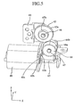
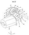
- Fig. 5 is a perspective view to show a driving means and a gear
- Fig. 6 is a perspective view to show how to attach the driving means and the gear onto a base shown in Fig. 5
- Fig. 7 is a side view of Fig. 6 when looking from Y direction
- Fig. 8 is a perspective view to show an arrangement of gears to transfer a driving force from a driving means to a feed screw axis
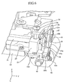
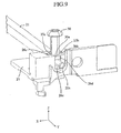
- Fig. 9 is a perspective view to show a height control mechanism of the feed screw axis
- Fig. 10 is an exploded perspective view of Fig. 9.
- directions X, Y and Z designated in these respective drawings are set to be common in these respective drawings.
- a reference numeral 10 designates a base
- 11 designates a disk motor which is fixed on the base 10 by locking screws 12a, 12b, 12c via supporting tables 13a, 13b, 13c which are fixed on the base 10 by a manner caulking and the like
- 12a, 12b, 12c designate locking screws
- 13a, 13b, 13c designate the supporting table which are fixed on the base 10
- 20 designates a guiding axis
- 21 designates a feed screw axis which movably supports an optical pick up 31 along a radial direction of the disk as well as the guiding axis
- 22 designates a shaft bearing which is fixed by the locking screw 23 on the base 10 to support enably to swing an end portion 21b of the feed screw axis 21.
- a reference numeral 23 designates a locking screw
- 24 designates a leaf spring which contacts with the end portion 21b of the feed screw axis 21 at tip end portion 24a to urge the feed screw axis 21 along its axis direction
- 25 designates a holding portion which regulates a positioning of the feed screw axis 21 in a direction perpendicular to the axial direction and a height direction
- 26 designates a movable portion which supports pivotally and enably to swing the feed screw axis 21
- 27 designates an elastic member which is arranged at a hole portion 25a of the holding portion 25 to energize the movable portion 26 in Z (+) direction
- 28 designates a gear which is made to be interlocked at an end portion 21a of the feed screw axis
- 29 designates a locking screw
- 30 designates a control screw which engages with a tap portion made on the base 10 and is arranged at a position where a tip portion 30a contacts with the movable portion 26, the control screw 30 consists the control
- a reference numeral 31 designates an optical pick up which moves along a radial direction of the disk when the feed screw axis 21 is rotated
- 32 designates a leaf spring whose nut portion 32a engages with a leading screw (not shown) made on the feed screw axis 21 for the optical pick up 31 to be moved along the radial direction of disk by a rotation of the feed screw axis
- 33 designates an urging spring which is fixed on the optical pick up 31 by locking screws 34, 35 to move along the radial direction of disk in a manner contacting with the guiding axis 20, and 34, 35 designate locking screws.
- a reference numeral 40 designates a thread motor (driving means) which is fixed on a gear base 41 by locking screws 42a, 42b for the feed screw axis 21 to be rotated by the gears, 42a, 42b designate locking screws, 43 designates a worm gear which is fixed on a shaft 40a of the thread motor 40, 44 designates gears which are supported by a supporting shaft 47 fixed on the gear base 41, in which a helical gear portion 44a engages with the worm gear 43, a flat gear portion 44b engages with a large gear 45a of the gears 45, 45 designates gears which are pivotally supported by a supporting axis 46 fixed on the gear base 41, 46 and 47 designate the supporting axes.
- the holding portion 25 shown in Fig. 9 and Fig. 10 is fixed on the base 10 by the locking screw 29.
- the movable portion 26 rotatably and pivotally supports the end portion 21a of feed screw axis 21 by a hole portion 26a to regulate the height along Z direction.
- the cut portion 25d, 25f regulate a positioning of the end portion 21a of feed screw 21 along X direction and support it rotatably and pivotally.
- a height along Z direction of the end portion 21a of feed screw axis 21 which is supported enably to go up and down along Z direction in relation to the holding portion 25 is defined to position by a height along Z direction of the movable portion 26.
- a positioning of the end portion 21a of feed screw axis 21 along Z direction is regulated by the movable portion 26 as described above.
- a positioning along X direction is regulated by the cut portions 25d, 25f which are arranged on the holding portion 25 fixed on the base 10, thereby it is made possible to decide position without effected by an operation of the control for the movable portion 26 along Z direction.
- a disk device in accordance with the Embodiment 1 of present invention brings about an effect that a number of parts which must be moves for the height control can be reduced, and thereby whole dimension of mechanism can be minimized by means that the height control mechanism of feed screw axis 21 are made as described above.
- the disk device also brings about an effect that a degree of freedom in designing for mechanism arrangement can be raised because it is made possible to arrange the thread motor 40 in a same side with the height control side. Further, because it is made possible that the height control is performed at both ends of the feed screw axis 21, it brings about an effect that the height control of whole feed screw axis 21 in relation to the base 10 can be achieved in time with the angle adjustment.
- Fig. 11 is a perspective view of relevant part to show the height control mechanism of feed screw axis
- Fig. 12 is an exploded perspective view to show the height control mechanism of feed screw axis
- Fig. 13 is a side view of Fig. 12 when looking from Y direction. Because the same reference numerals those used in Fig. 1 to Fig. 10 designate the same or the equivalent parts, further explanation on them will be omitted.
- the movable portion 26 has a swinging axis 26h which is arranged substantially parallel to a direction of the feed screw axis 21 and the swinging axis 26h engages with a hole portion 25h made on the holding portion 25.
- the holding portion 25 supports the movable portion 26 enably to swing around the swinging axis 26h.
- a reference symbol 26i designates a protruding portion made on the movable portion 26, it is arranged at a position at which it contacts with the tip portion 30a of control screw 30.
- screw axis 21 is defined to position by a height along Z direction of the movable portion 26 which is supported enably to swing around the swinging axis 26h in relation to the holding portion 25.
- a height control of the end portion 21a of feed screw 21 along Z direction can be realized.
- a position of the control screw 30 can be arbitrary arranged by means of changing a position of the protruding portion 26i which contacts with the control screw 30 as far as it is included within an area where the movable portion 26 can swing.
- a positioning of the end portion 21a of feed screw axis 21 along Z direction is regulated by the movable portion 26 as described above.
- a positioning along X direction is regulated by the cut portions 25f which is arranged on the holding portion 25 fixed on the base 10, thereby it is made possible to decide position without effected by an operation of the control for the movable portion 26 along Z direction.
- the disk device in accordance with the Embodiment 2 of present invention brings about an effect that a degree of freedom in designing for mechanism arrangement can be raised because it is made possible to easily change an arrangement of the control screw 30 in addition to the effect given by the above described Embodiment 1.
- the disk device in accordance with the present invention is suitable for a disk device in which it is required to prevent a scaling up of whole mechanism when the mechanism to achieve the angle adjustment of feed screw axis in relation to the base is installed.
Landscapes
- Moving Of Heads (AREA)
- Moving Of The Head For Recording And Reproducing By Optical Means (AREA)
- Transmission Devices (AREA)
Abstract
Description
Claims (4)
- A disk device comprising:a feed screw axis (21) to movably support an optical pick up (31) along a radial direction of disk;a movable portion (26) to support pivotally and enably to swing said feed screw axis (21);a driving means (40) for said feed screw axis (21) to be rotated by driving a gear (45) which engages with a gear (28) interlocked at an end portion of height control side of said feed screw axis (21); anda control means (30) to control a height of said movable portion (26).
- The disk device according to claim 1 characterized by that a shaft center of the gear (45) which is driven by said driving means (40), is arranged such that it is located in the same height of a middle point in a range of the height control by the height control means (30) and it is located on a line perpendicular to a direction of the height control by said height control means.
- The disk device according to claim 1 characterized by that a holding portion (25) which regulates a positioning of the feed screw axis (21) in a direction perpendicular to the axial direction and a height direction while the holding portion movably supports the movable portion (26) in the height direction, is fixed on a base (1).
- The disk device according to claim 1 characterized by that a swinging axis (26h) for the movable portion (26) to swing around an axis parallel to an axial direction of the feed screw axis (21), is arranged on said movable portion (26) and the holding portion (25) supports the swinging axis (26h) enably to swing.
Applications Claiming Priority (1)
| Application Number | Priority Date | Filing Date | Title |
|---|---|---|---|
| PCT/JP2001/009348 WO2003036645A1 (en) | 2001-10-24 | 2001-10-24 | Disc drive |
Publications (3)
| Publication Number | Publication Date |
|---|---|
| EP1441347A1 true EP1441347A1 (en) | 2004-07-28 |
| EP1441347A4 EP1441347A4 (en) | 2005-11-09 |
| EP1441347B1 EP1441347B1 (en) | 2006-10-04 |
Family
ID=11737865
Family Applications (1)
| Application Number | Title | Priority Date | Filing Date |
|---|---|---|---|
| EP01978893A Expired - Lifetime EP1441347B1 (en) | 2001-10-24 | 2001-10-24 | Disc drive |
Country Status (6)
| Country | Link |
|---|---|
| US (1) | US6948178B2 (en) |
| EP (1) | EP1441347B1 (en) |
| JP (1) | JP4184276B2 (en) |
| CN (1) | CN100380508C (en) |
| DE (1) | DE60123675T2 (en) |
| WO (1) | WO2003036645A1 (en) |
Families Citing this family (4)
| Publication number | Priority date | Publication date | Assignee | Title |
|---|---|---|---|---|
| JP3091275U (en) * | 2002-07-08 | 2003-01-24 | 船井電機株式会社 | Optical disk drive |
| CN1322499C (en) * | 2004-09-29 | 2007-06-20 | 常州市新科精密机械有限公司 | Optical pick-up device driver for optical disk reader |
| CN100356460C (en) * | 2004-12-24 | 2007-12-19 | 上海乐金广电电子有限公司 | Arrangement for adjusting deviation of optical driver |
| JP2009271969A (en) * | 2008-05-01 | 2009-11-19 | Funai Electric Co Ltd | Optical pickup and optical disc apparatus |
Family Cites Families (19)
| Publication number | Priority date | Publication date | Assignee | Title |
|---|---|---|---|---|
| JP2707289B2 (en) * | 1988-09-27 | 1998-01-28 | キヤノン株式会社 | Information recording / reproducing device |
| JPH02214024A (en) * | 1989-02-14 | 1990-08-27 | Sharp Corp | Tilt adjusting device for optical pickup |
| US5761183A (en) * | 1992-12-24 | 1998-06-02 | Olympus, Optical Co., Ltd. | Optical pickup |
| JP3194068B2 (en) * | 1994-09-14 | 2001-07-30 | 三菱電機株式会社 | Flexible disk unit |
| JP3158890B2 (en) * | 1994-09-30 | 2001-04-23 | 株式会社日立製作所 | Optical disk drive |
| JP3339975B2 (en) * | 1994-11-02 | 2002-10-28 | オリンパス光学工業株式会社 | Linear guide device |
| KR0183893B1 (en) * | 1996-06-27 | 1999-04-15 | 김광호 | Pickup phase adjustment apparatus of disk player |
| JPH10116479A (en) * | 1996-10-11 | 1998-05-06 | Matsushita Electric Ind Co Ltd | Optical head adjustment device |
| KR100259150B1 (en) * | 1997-11-28 | 2000-06-15 | 윤종용 | Optical Pickup Transfer Device |
| US5982735A (en) * | 1997-12-29 | 1999-11-09 | Industrial Technology Research Institute | Tilt angle adjustable mechanism for compact disc recording/reproducing device |
| JPH11224438A (en) | 1998-02-05 | 1999-08-17 | Sony Corp | Optical pickup device |
| JPH11238232A (en) * | 1998-02-19 | 1999-08-31 | Nec Home Electron Ltd | Disk device |
| JPH11283253A (en) | 1998-03-30 | 1999-10-15 | Matsushita Electric Ind Co Ltd | Optical pickup tilt adjustment device |
| JP3592563B2 (en) * | 1998-12-28 | 2004-11-24 | パイオニア株式会社 | Skew adjustment device for optical disk player |
| JP2001052346A (en) * | 1999-06-03 | 2001-02-23 | Matsushita Electric Ind Co Ltd | Optical pickup adjustment mechanism |
| JP2001006184A (en) * | 1999-06-23 | 2001-01-12 | Mitsumi Electric Co Ltd | Off-center adjusting mechanism for optical disk drive and adjusting method thereof |
| JP2001101671A (en) * | 1999-09-28 | 2001-04-13 | Alps Electric Co Ltd | Optical disk device |
| JP4067256B2 (en) * | 1999-11-25 | 2008-03-26 | 松下電器産業株式会社 | Pickup moving mechanism of optical disk apparatus |
| JP2001176086A (en) * | 1999-12-17 | 2001-06-29 | Kenwood Corp | Disk reproducing device |
-
2001
- 2001-10-24 US US10/432,233 patent/US6948178B2/en not_active Expired - Lifetime
- 2001-10-24 EP EP01978893A patent/EP1441347B1/en not_active Expired - Lifetime
- 2001-10-24 DE DE60123675T patent/DE60123675T2/en not_active Expired - Lifetime
- 2001-10-24 WO PCT/JP2001/009348 patent/WO2003036645A1/en not_active Ceased
- 2001-10-24 CN CNB018211879A patent/CN100380508C/en not_active Expired - Fee Related
- 2001-10-24 JP JP2003539046A patent/JP4184276B2/en not_active Expired - Fee Related
Also Published As
| Publication number | Publication date |
|---|---|
| CN100380508C (en) | 2008-04-09 |
| DE60123675D1 (en) | 2006-11-16 |
| EP1441347B1 (en) | 2006-10-04 |
| JPWO2003036645A1 (en) | 2005-02-17 |
| DE60123675T2 (en) | 2007-08-16 |
| US20040032819A1 (en) | 2004-02-19 |
| US6948178B2 (en) | 2005-09-20 |
| JP4184276B2 (en) | 2008-11-19 |
| EP1441347A4 (en) | 2005-11-09 |
| WO2003036645A1 (en) | 2003-05-01 |
| CN1483200A (en) | 2004-03-17 |
Similar Documents
| Publication | Publication Date | Title |
|---|---|---|
| KR100400340B1 (en) | Optical disk apparatus | |
| US5889755A (en) | Pickup adjusting apparatus of an optical disk player | |
| EP1441347B1 (en) | Disc drive | |
| JP4287446B2 (en) | Karakuri Clock | |
| US20010012261A1 (en) | Disk player capable of adjusting tilt of optical pickup | |
| EP0304262B1 (en) | Head driving apparatus | |
| GB2284922A (en) | Magnetic head positioning mechanism | |
| GB2274938A (en) | A head positioning apparatus | |
| KR20060097517A (en) | Pickup drive device of disc player | |
| JP2006326771A (en) | Adjusting mechanism and adjusting device | |
| CN1316466C (en) | Optical pickup system and disk drive with the same | |
| KR102933276B1 (en) | Rotary stage | |
| JP2002245734A (en) | Lead screw bearing structure and disk reproducing device | |
| JP3473126B2 (en) | Zoom lighting system | |
| JP3110698U (en) | Tilt adjustment mechanism | |
| JP2523978B2 (en) | Positioning table | |
| CA1325272C (en) | Head driving apparatus | |
| JP4143424B2 (en) | Optical disk device | |
| JP2584023Y2 (en) | Variable power optical device | |
| KR20080041674A (en) | Rotary Encoder and Drive | |
| JPS62177771A (en) | Carriage drive mechanism for floppy disk device | |
| JP3976510B2 (en) | Optical disk device | |
| JPS647499Y2 (en) | ||
| JP2001023321A (en) | Optical pickup feed mechanism | |
| KR0182440B1 (en) | Actuated mirror array panel adjusting apparatus |
Legal Events
| Date | Code | Title | Description |
|---|---|---|---|
| PUAI | Public reference made under article 153(3) epc to a published international application that has entered the european phase |
Free format text: ORIGINAL CODE: 0009012 |
|
| 17P | Request for examination filed |
Effective date: 20030522 |
|
| AK | Designated contracting states |
Kind code of ref document: A1 Designated state(s): AT BE CH CY DE DK ES FI FR GB GR IE IT LI LU MC NL PT SE TR |
|
| A4 | Supplementary search report drawn up and despatched |
Effective date: 20050926 |
|
| RIC1 | Information provided on ipc code assigned before grant |
Ipc: 7G 11B 7/08 B Ipc: 7G 11B 21/02 B Ipc: 7G 11B 7/085 A |
|
| RAP1 | Party data changed (applicant data changed or rights of an application transferred) |
Owner name: MITSUBISHI DENKI KABUSHIKI KAISHA |
|
| GRAP | Despatch of communication of intention to grant a patent |
Free format text: ORIGINAL CODE: EPIDOSNIGR1 |
|
| RBV | Designated contracting states (corrected) |
Designated state(s): DE |
|
| GRAS | Grant fee paid |
Free format text: ORIGINAL CODE: EPIDOSNIGR3 |
|
| GRAA | (expected) grant |
Free format text: ORIGINAL CODE: 0009210 |
|
| AK | Designated contracting states |
Kind code of ref document: B1 Designated state(s): DE |
|
| REF | Corresponds to: |
Ref document number: 60123675 Country of ref document: DE Date of ref document: 20061116 Kind code of ref document: P |
|
| PLBE | No opposition filed within time limit |
Free format text: ORIGINAL CODE: 0009261 |
|
| STAA | Information on the status of an ep patent application or granted ep patent |
Free format text: STATUS: NO OPPOSITION FILED WITHIN TIME LIMIT |
|
| 26N | No opposition filed |
Effective date: 20070705 |
|
| REG | Reference to a national code |
Ref country code: DE Ref legal event code: R084 Ref document number: 60123675 Country of ref document: DE Effective date: 20110707 Ref country code: DE Ref legal event code: R084 Ref document number: 60123675 Country of ref document: DE Effective date: 20110506 |
|
| PGFP | Annual fee paid to national office [announced via postgrant information from national office to epo] |
Ref country code: DE Payment date: 20161018 Year of fee payment: 16 |
|
| REG | Reference to a national code |
Ref country code: DE Ref legal event code: R119 Ref document number: 60123675 Country of ref document: DE |
|
| PG25 | Lapsed in a contracting state [announced via postgrant information from national office to epo] |
Ref country code: DE Free format text: LAPSE BECAUSE OF NON-PAYMENT OF DUE FEES Effective date: 20180501 |