EP1441336A1 - Disk drive - Google Patents
Disk drive Download PDFInfo
- Publication number
- EP1441336A1 EP1441336A1 EP01978891A EP01978891A EP1441336A1 EP 1441336 A1 EP1441336 A1 EP 1441336A1 EP 01978891 A EP01978891 A EP 01978891A EP 01978891 A EP01978891 A EP 01978891A EP 1441336 A1 EP1441336 A1 EP 1441336A1
- Authority
- EP
- European Patent Office
- Prior art keywords
- cam plate
- plate
- sub cam
- precut
- sub
- Prior art date
- Legal status (The legal status is an assumption and is not a legal conclusion. Google has not performed a legal analysis and makes no representation as to the accuracy of the status listed.)
- Granted
Links
Images




Classifications
-
- G—PHYSICS
- G11—INFORMATION STORAGE
- G11B—INFORMATION STORAGE BASED ON RELATIVE MOVEMENT BETWEEN RECORD CARRIER AND TRANSDUCER
- G11B17/00—Guiding record carriers not specifically of filamentary or web form, or of supports therefor
- G11B17/02—Details
- G11B17/04—Feeding or guiding single record carrier to or from transducer unit
- G11B17/05—Feeding or guiding single record carrier to or from transducer unit specially adapted for discs not contained within cartridges
- G11B17/051—Direct insertion, i.e. without external loading means
-
- G—PHYSICS
- G11—INFORMATION STORAGE
- G11B—INFORMATION STORAGE BASED ON RELATIVE MOVEMENT BETWEEN RECORD CARRIER AND TRANSDUCER
- G11B17/00—Guiding record carriers not specifically of filamentary or web form, or of supports therefor
- G11B17/22—Guiding record carriers not specifically of filamentary or web form, or of supports therefor from random access magazine of disc records
-
- G—PHYSICS
- G11—INFORMATION STORAGE
- G11B—INFORMATION STORAGE BASED ON RELATIVE MOVEMENT BETWEEN RECORD CARRIER AND TRANSDUCER
- G11B17/00—Guiding record carriers not specifically of filamentary or web form, or of supports therefor
- G11B17/22—Guiding record carriers not specifically of filamentary or web form, or of supports therefor from random access magazine of disc records
- G11B17/28—Guiding record carriers not specifically of filamentary or web form, or of supports therefor from random access magazine of disc records the magazine having a cylindrical shape with horizontal axis
Definitions
- the present invention relates to a disk device by which two kind of disk operating modes can be realized by means that a lever performs two kind of operations.
- a disk member which has a U shaped precut portion, and a locking lever which engages with a cam groove formed on the disk member to operate, are provided with a slidable locking plate which engages with precut portion of the disk member to regulate a rotating movement.
- the locking plate When the locking plate is slid to engage with the precut portion of disk member in a state the precut portion of disk member stops a position where it engages with the locking plate, rotating movement of the disk member is regulated. On the other hand the locking lever is released from an engagement by the slid locking plate, and moves along a cam groove on the disk member.
- disk device in the prior art technology is constituted as described above, the locking plate can be slid and engaged with precut portion of the disk member when the disk member stops accurately at a predetermined rotated position, however, there has been a problem that the locking plate cannot be inserted into the precut portion of disk member in a case when a stopping position of the disk member is shifted even in a little bit from the predetermined position.
- the present invention has been made to solve the above described problem and it is an object of the invention to provide a disk device in which a protruding portion at a tip of the locking plate can be inserted into the precut portion to release an engaging state of the locking lever even when the stopping position of a sub cam plate is shifted from a predetermined rotated position.
- a disk device in accordance with the present invention is characterized by that a precut portion of the sub cam plate and a protruding portion of the locking plate are made in a slanted shape and at the same time the sub cam plate is rotated by a pressure when the protruding portion is inserted into the precut portion.
- the disk device in accordance with the present invention is characterized by that a stopping position of the sub camplate is set such that a tip portion of the protruding portion is located at a central area of cut portion of the precut portion.
- the disk device in accordance with the present invention is characterized by that precut portion of the sub cam plate is made by cutting in a triangle shape, and the tip portion of protruding portion of the locking plate is made in a shape of acute angle.
- the disk device in accordance with the present invention is characterized by that a urging member which urges a rotating movement of the sub cam plate in a direction that is opposite to a pressure when the protruding portion is inserted into the precut portion.
- the disk device in accordance with the present invention is characterized by that the urging member is constituted by a spring, and one end of the spring is firmly fixed onto the main cam plate and another end of the spring is firmly fixed onto the locking plate.
- Fig. 1 is a perspective view to show an relevant part of disk device according to embodiment 1 of the present invention
- Fig. 2 is a perspective view to show a two overlaid type disk cam portion
- Fig. 3 is an exploded view to show the two overlaid type disk cam portion.
- a reference numeral 1 designates a main cam plate which is rotated by a motor
- 2 designates a sub cam plate which is rotatably supported on the same axis with the main cam plate 1 and a precut portion 2a is formed on a circumference thereof
- 3 designates a locking lever (engaging means) which makes the main cam plate 1 and the sub cam plate 2 to be engaged with each other
- 4 designates a spring (urging member) which urges the sub cam plate 2 in a direction that is opposite to a pressure when a protruding portion 6a is inserted into the precut portion 2a
- 5 designates a central axis to support the main cam plate 1 and the sub cam plate
- 6 designates a locking plate which makes the protruding portion 6a inserted into the precut portion 2a of the sub cam plate 2 to release an engaging state of the locking lever 3 when the sub cam plate 2 stops at a predetermined rotated position
- 10 designates the motor (driving means) to drive the main cam plate
- 11
- the locking lever 3 On the main cam plate 1, the locking lever 3 is rotatably fixed by a pin 1a to lock the rotating movement with the sub cam plate 2, and a pin 3a of the locking lever 3 engages with a cam groove 2b on the sub cam plate 2.
- the locking lever 3 is provided with a hole 3b which has a shape of oblong hole, and the locking lever is urged to one side by the spring 4, thereby the main cam plate 1 and the sub cam plate 2 are clamped by the same central axis 5.
- the locking plate 6 is provided with a protruding portion 6a to engage with the precut portion 2a of sub cam plate 2 and a pin 6b to operate the locking lever 3.
- Fig. 4 and Fig. 5 show a relation between the main cam plate 1 and the locking lever 3, especially Fig. 4 shows a state that the sub cam plate 2 is locked and Fig. 5 shows a state that the sub cam plate is released from the locked state.
- the locking lever 3 is urged to one side by the spring 4 as depicted in Fig. 4, and it is located in a position where the pin 3a abuts onto one wall of a hole 1c in the main cam plate 1 with the pin 1a as a rotating center. And the locking lever 3 engages with a protruding portion 1b on the main cam plate 1 and thereby a rotating movement of the locking lever 3 around the central axis 5 as a center is regulated.
- the locking lever 3 rotates around the central axis 5 as a center and at the same time it rotates around the pin 1a as a center as depicted in Fig. 5.
- FIG. 6 shows a state that a straight edge of the protruding portion 6a of locking plate 6 and precut portion 2a of the sub cam plate 2 are aligned along a line
- Fig. 7 shows a back side of the state depicted in Fig. 6.
- Fig. 8 shows a state that the locking plate 6 is slid and engaged with the sub cam plate 2
- Fig. 9 shows a back side of the state depicted in Fig. 8.
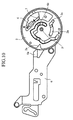
- FIG. 10 shows a state that a slanted edge of the protruding portion 6a of locking plate 6 and the precut portion 2a of sub cam plate 2 are aligned along a line
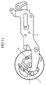
- Fig. 11 shows a back side of the state depicted in Fig. 10.
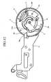
- Fig. 12 shows a state that the locking plate 6 is slid and engaged with the sub cam plate 2
- Fig. 13 shows a back side of the state depicted in Fig. 12.
- a stopping position of the main cam plate 1 is set on an area of center between two positions that the straight edge of protruding portion of the locking plate and a precut portion of the sub cam plate are aligned along a line, and that a slanted edge of protruding portion of the locking plate and the precut portion of sub cam plate are aligned along a line.
- the locking plate 6 is arranged as above described the locking action can be attained even when the rotational stopping position of the main cam plate 1 is shifted as far as it is located within the area between two stopping position depicted in Fig. 6 and Fig. 10.
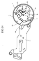
- FIG. 15 shows a state that the main cam plate 1 rotates within the concentric portion of cam groove 2b after the locking plate 6 engages with the sub cam plate 2. Because the rotating movement of sub cam plate 2 is prohibited, the pin 11a can not be moved and thereby the lever 11 is not worked
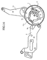
- Fig. 16 shows a state that the main cam plate 1 rotates to the same position which is depicted in Fig. 15 when the locking plate 6 does not engage with the sub cam plate 2. Because the sub cam plate 2 is rotated with the main cam plate 1, the pin 11a is moved to an outer peripheral side and thereby the lever 11 is worked.
- the disk device in accordance with the present invention is suitable for a disk device that selectively realizes the disk changing mode in which an arbitrary disk is selected from a plurality of disks and exchanged, and a disk playing mode in which an arbitrary disk is inserted into a slot and reproduce.
Landscapes
- Automatic Disk Changers (AREA)
- Transmission Devices (AREA)
- Feeding And Guiding Record Carriers (AREA)
Abstract
Description
- The present invention relates to a disk device by which two kind of disk operating modes can be realized by means that a lever performs two kind of operations.
- There has been a disk device which controls operation of a lever of two overlaid type cam in order to make enable to selectively realize a disk changing mode in which an arbitrary disk is selected from a plurality of disks and exchanged, and a disk playing mode in which an arbitrary disk is inserted into a slot and reproduced.
- In the disk device in the prior art technology, a disk member which has a U shaped precut portion, and a locking lever which engages with a cam groove formed on the disk member to operate, are provided with a slidable locking plate which engages with precut portion of the disk member to regulate a rotating movement.
- Hereinafter operation of the disk device will be explained.
- When the locking plate is slid to engage with the precut portion of disk member in a state the precut portion of disk member stops a position where it engages with the locking plate, rotating movement of the disk member is regulated. On the other hand the locking lever is released from an engagement by the slid locking plate, and moves along a cam groove on the disk member.
- Because disk device in the prior art technology is constituted as described above, the locking plate can be slid and engaged with precut portion of the disk member when the disk member stops accurately at a predetermined rotated position, however, there has been a problem that the locking plate cannot be inserted into the precut portion of disk member in a case when a stopping position of the disk member is shifted even in a little bit from the predetermined position.
- The present invention has been made to solve the above described problem and it is an object of the invention to provide a disk device in which a protruding portion at a tip of the locking plate can be inserted into the precut portion to release an engaging state of the locking lever even when the stopping position of a sub cam plate is shifted from a predetermined rotated position.
- A disk device in accordance with the present invention is characterized by that a precut portion of the sub cam plate and a protruding portion of the locking plate are made in a slanted shape and at the same time the sub cam plate is rotated by a pressure when the protruding portion is inserted into the precut portion.
- By this arrangement an effect is produced that the protruding portion at a tip of the locking plate can be inserted into the precut portion to release an engaging state of the locking lever even when a stopping position of the sub cam plate is shifted from a predetermined rotated position as far as it is located within an area where the tip portion of protruding portion of the locking plate can abut onto a slanted edge of the precut portion of sub cam plate.
- The disk device in accordance with the present invention is characterized by that a stopping position of the sub camplate is set such that a tip portion of the protruding portion is located at a central area of cut portion of the precut portion.
- By this arrangement an effect is produced that the area where the protruding portion can be inserted into the precut portion, can be expanded.
- The disk device in accordance with the present invention is characterized by that precut portion of the sub cam plate is made by cutting in a triangle shape, and the tip portion of protruding portion of the locking plate is made in a shape of acute angle.
- By this arrangement an effect is produced that the area where the protruding portion can be inserted into the precut portion, can be expanded without including complicated constitution.
- The disk device in accordance with the present invention is characterized by that a urging member which urges a rotating movement of the sub cam plate in a direction that is opposite to a pressure when the protruding portion is inserted into the precut portion.
- By this arrangement an effect is produced that a protruding portion at a tip of the locking plate can be inserted into the precut portion to release the engaging state of locking lever even when a stopping position of the sub cam plate is shifted from a predetermined rotated position as far as it is located within an area where the tip portion of protruding portion of the locking plate can abut onto a slanted edge of the precut portion of sub cam plate.
- The disk device in accordance with the present invention is characterized by that the urging member is constituted by a spring, and one end of the spring is firmly fixed onto the main cam plate and another end of the spring is firmly fixed onto the locking plate.
- By this arrangement an effect is produced that the area where the protruding portion can be inserted into the precut portion, can be expanded without including complicated constitution.
-
- Fig. 1 is a perspective view to show a relevant part of
disk device according to
embodiment 1 of the present invention. - Fig. 2 is a perspective view to show a two overlaid type disk cam portion.
- Fig. 3 is an exploded view to show the two overlaid type disk cam portion.
- Fig. 4 is an explanatory diagram to show a state that a sub cam plate is locked.
- Fig. 5 is an explanatory diagram to show a state that the sub cam plate is released from a locked state.
- Fig. 6 is an explanatory diagram to show a state that a straight edge of protruding portion of the locking plate and a precut portion of the sub cam plate are aligned along a line.
- Fig. 7 is an explanatory diagram to show the state depicted in Fig. 6 when viewed from a back side.
- Fig. 8 is an explanatory diagram to show a state that the locking plate is slid and engaged with the sub cam plate from the state depicted in Fig. 6.
- Fig. 9 is an explanatory diagram to show the state depicted in Fig. 8 when viewed from the back side.
- Fig. 10 is an explanatory diagram to show a state that a slanted edge of protruding portion of the locking plate and the precut portion of sub cam plate are aligned along a line.
- Fig. 11 is an explanatory diagram to show the state depicted in Fig. 10 when viewed from the back side.
- Fig. 12 is an explanatory diagram to show a state that the locking plate is slid and engaged with the sub cam plate from the state depicted in Fig. 9.
- Fig. 13 is an explanatory diagram to show the state depicted in Fig. 12 when viewed from the back side.
- Fig. 14 is an explanatory diagram to show one example of setting for stopping position of a main cam plate.
- Fig. 15 is an explanatory diagram to show a state that the main cam plate rotates within a concentric portion of cam groove after the locking plate engages with the sub cam plate.
- Fig. 16 is an explanatory diagram to show a state that the main cam plate rotates to the same position which is depicted in Fig. 15 when the locking plate has not engaged with the sub cam plate.
-
- For explaining the present invention in more detail, a best mode for carrying out the invention will be described hereinafter with reference to the accompanied drawings.
- Fig. 1 is a perspective view to show an relevant part of disk device according to
embodiment 1 of the present invention, Fig. 2 is a perspective view to show a two overlaid type disk cam portion and Fig. 3 is an exploded view to show the two overlaid type disk cam portion. - In the drawings a
reference numeral 1 designates a main cam plate which is rotated by amotor main cam plate 1 and aprecut portion 2a is formed on a circumference thereof, 3 designates a locking lever (engaging means) which makes themain cam plate 1 and thesub cam plate 2 to be engaged with each other, 4 designates a spring (urging member) which urges thesub cam plate 2 in a direction that is opposite to a pressure when a protrudingportion 6a is inserted into theprecut portion main cam plate 1 and thesub cam plate portion 6a inserted into theprecut portion 2a of thesub cam plate 2 to release an engaging state of thelocking lever 3 when thesub cam plate 2 stops at a predetermined rotated position, 10 designates the motor (driving means) to drive themain cam plate main cam plate 1 or thesub cam plate 2 by thelocking lever 3. - Hereinafter an operation of
embodiment 1 will be explained. - On the
main cam plate 1, thelocking lever 3 is rotatably fixed by a pin 1a to lock the rotating movement with thesub cam plate 2, and apin 3a of thelocking lever 3 engages with acam groove 2b on thesub cam plate 2. - The
locking lever 3 is provided with ahole 3b which has a shape of oblong hole, and the locking lever is urged to one side by thespring 4, thereby themain cam plate 1 and thesub cam plate 2 are clamped by the samecentral axis 5. - The
locking plate 6 is provided with a protrudingportion 6a to engage with theprecut portion 2a ofsub cam plate 2 and apin 6b to operate thelocking lever 3. - Fig. 4 and Fig. 5 show a relation between the
main cam plate 1 and thelocking lever 3, especially Fig. 4 shows a state that thesub cam plate 2 is locked and Fig. 5 shows a state that the sub cam plate is released from the locked state. - Typically the
locking lever 3 is urged to one side by thespring 4 as depicted in Fig. 4, and it is located in a position where thepin 3a abuts onto one wall of ahole 1c in themain cam plate 1 with the pin 1a as a rotating center. And thelocking lever 3 engages with a protrudingportion 1b on themain cam plate 1 and thereby a rotating movement of thelocking lever 3 around thecentral axis 5 as a center is regulated. - When a locking is released by an action of the locking lever 6 (a detail will be described later), the
locking lever 3 rotates around thecentral axis 5 as a center and at the same time it rotates around the pin 1a as a center as depicted in Fig. 5. - At this point Fig. 6 shows a state that a straight edge of the
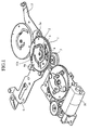
protruding portion 6a oflocking plate 6 andprecut portion 2a of thesub cam plate 2 are aligned along a line, and Fig. 7 shows a back side of the state depicted in Fig. 6. And Fig. 8 shows a state that thelocking plate 6 is slid and engaged with thesub cam plate 2, and Fig. 9 shows a back side of the state depicted in Fig. 8. - In the state depicted in Fig. 6, a rotating movement of the
sub cam plate 2 around thecentral axis 5 as a center is not caused even when thelocking plate 6 is slid, and only a rotating movement of thelocking lever 3 is performed around the pin 1a as a center bypin 6a of thelocking plate 6. - Because the
pin 3a is moved to a concentric portion of thecam groove 2b by this rotating movement, an engagement between thesub cam plate 2 and themain cam plate 1 is released. At this point thesub cam plate 2 is in a state to stop the rotating movement and only themain cam plate 1 becomes rotatable within the concentric portion ofcam groove 2b. - Next Fig. 10 shows a state that a slanted edge of the
protruding portion 6a oflocking plate 6 and theprecut portion 2a ofsub cam plate 2 are aligned along a line, and Fig. 11 shows a back side of the state depicted in Fig. 10. Moreover Fig. 12 shows a state that thelocking plate 6 is slid and engaged with thesub cam plate 2, and Fig. 13 shows a back side of the state depicted in Fig. 12. - In the state depicted in Fig. 10, when the
locking plate 6 is slid, thesub cam plate 2 performs a rotating movement around thecentral axis 5 as a center till theprecut portion 2a and theprotruding portion 6a are matched. At this point a drivingpin 11a of thelever 11 is located at a position in order not to disturb the rotating movement ofsub cam plate 2. While this rotating movement is performed, thelocking lever 3 performs its own rotating movement aroundcentral axis 5 as a center because thepin 3a engages with thecam groove 2b, and at the same time a rotating movement of thepin 6a oflocking plate 6 is performed around the pin 1a as a center. By this movement while thesub cam plate 2 is in a state to stop the rotating movement, only themain cam plate 1 becomes rotatable within the concentric portion ofcam groove 2b in the same manner as depicted in Fig. 8. - In this respect because the engagement of
locking plate 6 onto thesub cam plate 2 can be performed within an area from a stopping position depicted in Fig. 6 to a stopping position depicted in Fig. 10, a stopping position of themain cam plate 1, while the engagement oflocking plate 6 is performed, is set on an area of center between two positions that the straight edge of protruding portion of the locking plate and a precut portion of the sub cam plate are aligned along a line, and that a slanted edge of protruding portion of the locking plate and the precut portion of sub cam plate are aligned along a line. - Because the
locking plate 6 is arranged as above described the locking action can be attained even when the rotational stopping position of themain cam plate 1 is shifted as far as it is located within the area between two stopping position depicted in Fig. 6 and Fig. 10. - And in a case when a lock releasing action is performed to release the engagement of
locking plate 6, it is possible to be reset to the locking state depicted in Fig. 4 because thelocking lever 3 is pulled back by thespring 4 regardless of rotational stopping position of themain cam plate 1. - By this arrangement it is made possible to absorb a stopping error caused by a control for stopping the
motor 10, a stopping error of themain cam plate 1 caused by mechanical rattling or mechanical variation and the like. - At this point Fig. 15 shows a state that the
main cam plate 1 rotates within the concentric portion ofcam groove 2b after thelocking plate 6 engages with thesub cam plate 2. Because the rotating movement ofsub cam plate 2 is prohibited, thepin 11a can not be moved and thereby thelever 11 is not worked - Fig. 16 shows a state that the
main cam plate 1 rotates to the same position which is depicted in Fig. 15 when the lockingplate 6 does not engage with thesub cam plate 2. Because thesub cam plate 2 is rotated with themain cam plate 1, thepin 11a is moved to an outer peripheral side and thereby thelever 11 is worked. - By this constitution a selection from two different cam groove pattern can be performed within the same rotating area going along with allowance of stopping error of the
main cam plate 1. - As set forth above, the disk device in accordance with the present invention is suitable for a disk device that selectively realizes the disk changing mode in which an arbitrary disk is selected from a plurality of disks and exchanged, and a disk playing mode in which an arbitrary disk is inserted into a slot and reproduce.
Claims (5)
- A disk device comprising:a main cam plate (1) which is rotated by a driving means (10) ;a sub cam plate (2) which is rotatably supported on the same axis (5) as said main cam plate and a precut portion (2a) is made on a circumference thereof;an engaging means (3) which makes said main cam plate (1) and said sub cam plate (2) engaged with each other;a lever (11) which rotates with a rotating movement of said sub cam plate (2) when said main cam plate (1) and said sub cam plate (2) are engaged together by said engaging means (3); anda locking plate (6) which makes a protruding portion (6a) inserted into the precut portion (2a) on said sub cam plate (2) to release engaging state of the engaging means (3) when the sub cam plate (2) stops at a predetermined rotated position, characterized by that
the precut portion (2a) of said sub cam plate (2) and the protruding portion (6a) of said locking plate (6) are made in a slanted shape and at the same time said sub cam plate (2) is rotated by a pressure when said protruding portion (6a) is inserted into said precut portion (2a). - The disk device according to claim 1 characterized by that a stopping position of the sub cam plate (2) is set such that a tip portion of the protruding portion (6a) is located at a central area of cut portion of the precut portion (2a).
- The disk device according to claim 1 characterized by that precut portion (2a) of the sub cam plate (2) is made by cutting in a triangle shape, and the tip portion of protruding portion (6a) of the locking plate (6) is made in a shape of acute angle.
- The disk device according to claim 1 characterized by that a urging member (4) which urges the sub cam plate (2) in a direction that is opposite to the pressure when the protruding portion (6a) is inserted into the precut portion (2a).
- The disk device according to claim 4 characterized by that the urging member (4) is constituted by a spring, and one end of the spring is firmly fixed onto the main cam plate (1) and another end of the spring is firmly fixed onto the locking plate (6).
Applications Claiming Priority (1)
| Application Number | Priority Date | Filing Date | Title |
|---|---|---|---|
| PCT/JP2001/009346 WO2003036637A1 (en) | 2001-10-24 | 2001-10-24 | Disk drive |
Publications (3)
| Publication Number | Publication Date |
|---|---|
| EP1441336A1 true EP1441336A1 (en) | 2004-07-28 |
| EP1441336A4 EP1441336A4 (en) | 2006-06-21 |
| EP1441336B1 EP1441336B1 (en) | 2009-01-21 |
Family
ID=11737863
Family Applications (1)
| Application Number | Title | Priority Date | Filing Date |
|---|---|---|---|
| EP01978891A Expired - Lifetime EP1441336B1 (en) | 2001-10-24 | 2001-10-24 | Disk drive |
Country Status (6)
| Country | Link |
|---|---|
| US (1) | US6912720B2 (en) |
| EP (1) | EP1441336B1 (en) |
| JP (1) | JP3779304B2 (en) |
| CN (1) | CN1483196A (en) |
| DE (1) | DE60137548D1 (en) |
| WO (1) | WO2003036637A1 (en) |
Family Cites Families (8)
| Publication number | Priority date | Publication date | Assignee | Title |
|---|---|---|---|---|
| US4352132A (en) * | 1980-07-18 | 1982-09-28 | Data Master | Floppy disc drive |
| JPS5969537A (en) * | 1982-10-15 | 1984-04-19 | Clarion Co Ltd | Intermittently interlocking mechanism |
| US4685009A (en) * | 1984-02-27 | 1987-08-04 | Samsung Electronics Co., Ltd. | Cassette loading apparatus for video cassette recorder |
| JPS6398867A (en) | 1986-10-14 | 1988-04-30 | Matsushita Electric Ind Co Ltd | Changer |
| JPH0831235B2 (en) * | 1988-07-28 | 1996-03-27 | パイオニア株式会社 | Disc loading device |
| JP2820839B2 (en) | 1992-06-15 | 1998-11-05 | アルパイン株式会社 | Disc player having disc positioning mechanism |
| KR970006182B1 (en) * | 1992-07-04 | 1997-04-24 | 삼성전자 주식회사 | Magazine auto ejection device of cdp for automobile |
| JPH0831071A (en) | 1994-07-14 | 1996-02-02 | Sony Corp | Disc changer device |
-
2001
- 2001-10-24 EP EP01978891A patent/EP1441336B1/en not_active Expired - Lifetime
- 2001-10-24 US US10/432,235 patent/US6912720B2/en not_active Expired - Lifetime
- 2001-10-24 WO PCT/JP2001/009346 patent/WO2003036637A1/en not_active Ceased
- 2001-10-24 DE DE60137548T patent/DE60137548D1/en not_active Expired - Lifetime
- 2001-10-24 JP JP2003539039A patent/JP3779304B2/en not_active Expired - Fee Related
- 2001-10-24 CN CNA01821293XA patent/CN1483196A/en active Pending
Non-Patent Citations (2)
| Title |
|---|
| No further relevant documents disclosed * |
| See also references of WO03036637A1 * |
Also Published As
| Publication number | Publication date |
|---|---|
| US6912720B2 (en) | 2005-06-28 |
| JPWO2003036637A1 (en) | 2005-02-17 |
| US20040013006A1 (en) | 2004-01-22 |
| JP3779304B2 (en) | 2006-05-24 |
| DE60137548D1 (en) | 2009-03-12 |
| EP1441336B1 (en) | 2009-01-21 |
| EP1441336A4 (en) | 2006-06-21 |
| CN1483196A (en) | 2004-03-17 |
| WO2003036637A1 (en) | 2003-05-01 |
Similar Documents
| Publication | Publication Date | Title |
|---|---|---|
| KR20010022938A (en) | Disc tumbler lock and key | |
| JP4729277B2 (en) | Tool device protective hood structure | |
| JP2001180349A (en) | Swivel type child seat | |
| JP4770561B2 (en) | Vehicle seat turning device | |
| DE10250507A1 (en) | Steering wheel lock device | |
| JP2006516922A (en) | Apparatus and method for assembling a recliner mechanism | |
| EP1441336A1 (en) | Disk drive | |
| JP5319241B2 (en) | Electric tool | |
| US7802271B2 (en) | Disk clamping device | |
| EP0822549B1 (en) | Disk player | |
| JP7210005B2 (en) | Coating film transfer tool | |
| US5531132A (en) | Cam apparatus using an electromagnet and gears for decelerating a motor | |
| JPH04128727A (en) | Diaphragm device | |
| JP2002033031A (en) | Switch mechanism for electric power tool | |
| JP2002008489A (en) | Trigger switch | |
| US6330219B1 (en) | Disk recording/reproducing device | |
| JP4073433B2 (en) | Disk clamp mechanism of disk device | |
| JP2020172172A (en) | Shift device | |
| WO2007136365A1 (en) | Ratchet screwdriver and construction method | |
| JPH10189313A (en) | Lock mechanism for rotary knob | |
| JP2002142894A (en) | Reclining device | |
| JP4698570B2 (en) | Disk unit | |
| JP4162353B2 (en) | Wheel lock device | |
| EP0401748A2 (en) | Print wheel selection type compact printer | |
| JP2004185695A (en) | Clamp mechanism and information reproducing mechanism |
Legal Events
| Date | Code | Title | Description |
|---|---|---|---|
| PUAI | Public reference made under article 153(3) epc to a published international application that has entered the european phase |
Free format text: ORIGINAL CODE: 0009012 |
|
| 17P | Request for examination filed |
Effective date: 20030528 |
|
| AK | Designated contracting states |
Kind code of ref document: A1 Designated state(s): AT BE CH CY DE DK ES FI FR GB GR IE IT LI LU MC NL PT SE TR |
|
| AX | Request for extension of the european patent |
Extension state: AL LT LV MK RO SI |
|
| RAP1 | Party data changed (applicant data changed or rights of an application transferred) |
Owner name: MITSUBISHI DENKI KABUSHIKI KAISHA |
|
| A4 | Supplementary search report drawn up and despatched |
Effective date: 20060523 |
|
| 17Q | First examination report despatched |
Effective date: 20061005 |
|
| GRAP | Despatch of communication of intention to grant a patent |
Free format text: ORIGINAL CODE: EPIDOSNIGR1 |
|
| RBV | Designated contracting states (corrected) |
Designated state(s): DE |
|
| GRAS | Grant fee paid |
Free format text: ORIGINAL CODE: EPIDOSNIGR3 |
|
| GRAA | (expected) grant |
Free format text: ORIGINAL CODE: 0009210 |
|
| AK | Designated contracting states |
Kind code of ref document: B1 Designated state(s): DE |
|
| REF | Corresponds to: |
Ref document number: 60137548 Country of ref document: DE Date of ref document: 20090312 Kind code of ref document: P |
|
| PLBE | No opposition filed within time limit |
Free format text: ORIGINAL CODE: 0009261 |
|
| STAA | Information on the status of an ep patent application or granted ep patent |
Free format text: STATUS: NO OPPOSITION FILED WITHIN TIME LIMIT |
|
| 26N | No opposition filed |
Effective date: 20091022 |
|
| REG | Reference to a national code |
Ref country code: DE Ref legal event code: R084 Ref document number: 60137548 Country of ref document: DE Effective date: 20110627 Ref country code: DE Ref legal event code: R084 Ref document number: 60137548 Country of ref document: DE Effective date: 20110506 |
|
| PGFP | Annual fee paid to national office [announced via postgrant information from national office to epo] |
Ref country code: DE Payment date: 20131016 Year of fee payment: 13 |
|
| REG | Reference to a national code |
Ref country code: DE Ref legal event code: R119 Ref document number: 60137548 Country of ref document: DE |
|
| PG25 | Lapsed in a contracting state [announced via postgrant information from national office to epo] |
Ref country code: DE Free format text: LAPSE BECAUSE OF NON-PAYMENT OF DUE FEES Effective date: 20150501 |