EP1441263A2 - A method and device for multiplex holographic recording - Google Patents
A method and device for multiplex holographic recording Download PDFInfo
- Publication number
- EP1441263A2 EP1441263A2 EP04001200A EP04001200A EP1441263A2 EP 1441263 A2 EP1441263 A2 EP 1441263A2 EP 04001200 A EP04001200 A EP 04001200A EP 04001200 A EP04001200 A EP 04001200A EP 1441263 A2 EP1441263 A2 EP 1441263A2
- Authority
- EP
- European Patent Office
- Prior art keywords
- phase
- recording
- phase code
- holograms
- multiplexing
- Prior art date
- Legal status (The legal status is an assumption and is not a legal conclusion. Google has not performed a legal analysis and makes no representation as to the accuracy of the status listed.)
- Withdrawn
Links
Images





Classifications
-
- G—PHYSICS
- G11—INFORMATION STORAGE
- G11B—INFORMATION STORAGE BASED ON RELATIVE MOVEMENT BETWEEN RECORD CARRIER AND TRANSDUCER
- G11B7/00—Recording or reproducing by optical means, e.g. recording using a thermal beam of optical radiation by modifying optical properties or the physical structure, reproducing using an optical beam at lower power by sensing optical properties; Record carriers therefor
- G11B7/004—Recording, reproducing or erasing methods; Read, write or erase circuits therefor
- G11B7/0065—Recording, reproducing or erasing by using optical interference patterns, e.g. holograms
-
- G—PHYSICS
- G03—PHOTOGRAPHY; CINEMATOGRAPHY; ANALOGOUS TECHNIQUES USING WAVES OTHER THAN OPTICAL WAVES; ELECTROGRAPHY; HOLOGRAPHY
- G03H—HOLOGRAPHIC PROCESSES OR APPARATUS
- G03H1/00—Holographic processes or apparatus using light, infrared or ultraviolet waves for obtaining holograms or for obtaining an image from them; Details peculiar thereto
- G03H1/04—Processes or apparatus for producing holograms
- G03H1/10—Processes or apparatus for producing holograms using modulated reference beam
- G03H1/12—Spatial modulation, e.g. ghost imaging
-
- G—PHYSICS
- G03—PHOTOGRAPHY; CINEMATOGRAPHY; ANALOGOUS TECHNIQUES USING WAVES OTHER THAN OPTICAL WAVES; ELECTROGRAPHY; HOLOGRAPHY
- G03H—HOLOGRAPHIC PROCESSES OR APPARATUS
- G03H1/00—Holographic processes or apparatus using light, infrared or ultraviolet waves for obtaining holograms or for obtaining an image from them; Details peculiar thereto
- G03H1/26—Processes or apparatus specially adapted to produce multiple sub- holograms or to obtain images from them, e.g. multicolour technique
-
- G—PHYSICS
- G11—INFORMATION STORAGE
- G11C—STATIC STORES
- G11C13/00—Digital stores characterised by the use of storage elements not covered by groups G11C11/00, G11C23/00, or G11C25/00
- G11C13/04—Digital stores characterised by the use of storage elements not covered by groups G11C11/00, G11C23/00, or G11C25/00 using optical elements ; using other beam accessed elements, e.g. electron or ion beam
- G11C13/042—Digital stores characterised by the use of storage elements not covered by groups G11C11/00, G11C23/00, or G11C25/00 using optical elements ; using other beam accessed elements, e.g. electron or ion beam using information stored in the form of interference pattern
-
- G—PHYSICS
- G03—PHOTOGRAPHY; CINEMATOGRAPHY; ANALOGOUS TECHNIQUES USING WAVES OTHER THAN OPTICAL WAVES; ELECTROGRAPHY; HOLOGRAPHY
- G03H—HOLOGRAPHIC PROCESSES OR APPARATUS
- G03H1/00—Holographic processes or apparatus using light, infrared or ultraviolet waves for obtaining holograms or for obtaining an image from them; Details peculiar thereto
- G03H1/26—Processes or apparatus specially adapted to produce multiple sub- holograms or to obtain images from them, e.g. multicolour technique
- G03H1/2645—Multiplexing processes, e.g. aperture, shift, or wavefront multiplexing
- G03H2001/2675—Phase code multiplexing, wherein the sub-holograms are multiplexed according to spatial modulation of the reference beam
Definitions
- the present invention relates to a method and device for holographic recording, and more particularly, to a method and device for holographic recording which enable increased recording density by improving the selectivity along the Y direction defined with reference to the optical axes of a signal beam and reference beam.
- Holographic recording is known as one method for realizing high-density information recording on a recording medium.
- information is recorded by overlapping a signal beam and a reference beam on the holographic recording medium to write the interference fringes formed thereby.
- the information recorded in the recording medium can be reproduced by irradiating the recording medium with the reference beam.
- the reference beam projected onto the recording medium is diffracted by the diffraction grating formed by the interference fringes, thereby causing 2-dimensional information to appear as reproduced information.
- high speed reproduction can be realized.
- 3-dimensional recording of interference fringes is commonly performed by positively utilizing the thickness direction of the recording medium.
- the recording medium By making the recording medium thicker, it is possible to enhance diffraction efficiency. And by multiplex recording, it is possible to further increase the recording capacity.
- multiplexing methods such as angular multiplexing, wavelength multiplexing, shift multiplexing, phase code multiplexing, peristrophic multiplexing and spatial multiplexing.
- Shift multiplexing records holograms so as to partially overlap.
- the X direction is defined as the direction of a line of intersection between a plane including the optical axes of the signal beam and reference beam (incidence plane) and the recording plane of the recording medium
- the Y direction is defined as the direction of a line lying normal to the incidence plane and intersecting the line of intersection. Since Bragg selectivity along the Y direction is low, it is difficult to improve degree of multiplexing along the Y direction in shift multiplexing.
- the Bragg selectivity is said to be high, and in the opposite case, the Bragg selectivity is said to be low.
- the Bragg selectivity along the Y direction is low and selectivity along the Y direction is therefore improved utilizing aperture selectivity.
- a holographic recording method for recording information as phase information of light by projecting a signal beam and a reference beam onto a recording medium, wherein an X direction is defined as the direction of a line of intersection between a plane including the optical axes of the signal beam and reference beam (incidence plane) and the recording plane of the recording medium, and the Y direction is defined as the direction of a line lying normal to the incidence plane and intersecting said line of intersection, comprising steps of using the reference beam modulated with a first phase code to record a first hologram at a predetermined position; and using the reference beam modulated with a second phase code whose pattern is different from that of the first phase code to record at a position shifted in the Y direction a second hologram that partially overlaps the first hologram.
- the present invention it is possible to improve selectivity along the Y direction, and therefore, to increase the recording density by improving the degree of multiplexing along the Y direction in shift multiplexing.
- the holographic recording method further comprises a step of using the reference beam modulated with a third phase code whose pattern is different from that of the first and second phase codes to record at a position shifted in the Y direction a third hologram that partially overlaps the first and second holograms, a correlation between the third phase code and the second phase code being set lower than a correlation between the third phase code and the first phase code.
- the holographic recording method includes a step of using the reference beam modulated with the first phase code to record at position shifted to the X direction a fourth hologram that partially overlaps the first hologram.
- a holographic recording method for recording information as phase information of light by projecting a signal beam and a reference beam onto a recording medium, wherein an X direction is defined as the direction of a line of intersection between a plane including the optical axes of the signal beam and reference beam (incidence plane) and the recording plane of the recording medium, and the Y direction is defined as the direction of a line lying normal to the incidence plane and intersecting said line of intersection, comprising a step of recording holograms by shift multiplexing at least in the Y direction and using phase code multiplexing in combination with the shift code multiplexing in the Y direction.
- the phase codes used in the phase code multiplexing have lower correlation with increasing overlap between two holograms recorded by shift multiplexing in the Y direction.
- orthogonal phase codes are used for holograms adjacent along the Y direction.
- the holograms are recorded along both the X direction and Y direction by shift multiplexing.
- the same phase code is used for holograms recorded along the X direction.
- phase codes are used for holograms recorded along the X direction.
- the recording medium is a disk
- the X direction and Y direction are the tracking direction and the radial direction of the disk, respectively.
- a holographic recording device for recording information as phase information of light by projecting a signal beam and a reference beam onto a recording medium
- a laser beam source for dividing the beam from the laser beam source; a spatial light modulator for generating a signal beam containing information by modulating the intensity of one divided beam; a phase spatial light modulator for generating a reference beam by modulating the phase of the other divided beam with a predetermined phase code; a controller for controlling the incidence position of the signal beam and reference beam on the recording medium; wherein an X direction is defined as the direction of a line of intersection between an incidence plane including the optical axes of the signal beam and reference beam and the recording plane of the recording medium, a Y direction is defined as the direction of a line perpendicular to the incidence plane, and the controller records holograms by shift multiplexing at least in the Y direction and using phase code multiplexing in combination with the shift multiplexing in the Y direction
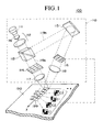
- Figure 1 is a schematic diagram showing the principle of the holographic recording of the present invention.
- holograms are recorded in a recording medium 190 with a holographic recording device 100.
- the holographic recording device 100 comprises at least an optical pickup 110 for generating beams projected onto the recording medium 190.
- the optical pickup 110 comprises a laser beam source 111 used for recording and reproducing, a beam expander 112 for expanding the size of the beam 119 from the laser beam source 111, a beam splitter 113 for dividing the expanded beam 119 into two beams, a spatial light modulator (SLM) 114 for producing a signal beam carrying information by spatially modulating the intensity of one divided beam 119a, a mirror 115 for changing the optical path of the other divided beam 119b, a phase spatial light modulator (phase SLM) 116 for spatially modulating the phase of the beam 119b reflected at the mirror 115, and two Fourier transformation lenses 117 and 118.
- SLM spatial light modulator
- a solid state laser for example, is used as the laser beam source 111. It emits a linearly polarized coherent beam.
- the beam 119 emitted from the laser beam source 111 is expanded and collimated by the beam expander 112, after which it enters the beam splitter 113.
- the beam 119a from the beam splitter 113 enters the SLM 114.
- the SLM 114 has a large number of pixels arranged in a matrix and spatially modulates the intensity of the beam 119a by selectively passing or blocking the beam at each pixel.
- a liquid crystal element for example, is used as the SLM 114.
- the beam 119b from the beam splitter 113 enters the phase SLM 116.
- the phase SLM 116 also has a large number of pixels arranged in a matrix and spatially modulates the phase of the beam by selecting the phase of the beam at each pixel. For example, selection between phase differences 0 (rad) or n (rad) relative a predetermined phase is made at each pixel.
- specific modulation patterns (phase codes) used for such modulation are supplied to the phase SLM 116 in accordance with prescribed conditions.
- a liquid crystal element for example, is also used as the phase SLM 116.
- the modulated beams 119a and 119b are simultaneously projected through the Fourier transformation lenses 117 and 118, respectively, onto the same position of the recording medium from different directions as the signal beam and the reference beam. This overlapping projection of the signal beam and reference beam forms interference fringes at the region of the beam spots and a hologram 199 carrying the information is therefore recorded.
- the optical paths of the signal beam and reference beam projected onto the recording medium 190 are set to include the optical axes of the beams in an "incidence plane" lying perpendicular to the surface of the recording medium 190 and to make their incidence angles to the surface equal.
- the X direction is defined as the direction of the line of intersection between the incidence plane and the recording plane of the recording medium
- the Y direction is defined as the direction of a line lying normal to the incidence plane that perpendicularly intersects said line of intersection.
- the recording of holograms 199 progresses sequentially in the Y direction on the recording medium 190.
- the spots of the signal and reference beams are shifted in the Y direction sequentially, and the holographic recording therefore proceeds in the Y direction.
- the recording in the Y direction is shift multiplexing and the shift amount to the next recording region is therefore set small so that at least adjacent holograms partially overlap.
- phase code multiplex recording in combination with the shift multiplexing, shortcomings of the shift multiplexing, such as that Bragg selectivity is low, are compensated.
- the correlation of the phase codes is set lower as the overlap of the holograms is higher, and an orthogonal phase code pattern is preferably used.
- shift multiplexing in which the degree of multiplexing of overlapping adjacent holograms is "2" is carried out as follows.
- a hologram H1 is recorded with a phase code C1.
- the spots of the signal and reference beams are shifted in the Y direction and a hologram H2 is recorded with a second code C2 so as to partially overlap the first hologram H1.
- a pattern orthogonal to the first phase code C1 is used as the second phase code C2.
- the spots of the signal and reference beams are shifted in the Y direction and a hologram H3 is recorded with the first code C1 so as to partially overlap the second hologram H2.
- phase codes C1 and C2 are used alternately but three phase codes C1, C2 and C3 may be used by turns.
- the shift amount in the Y direction is set smaller than in degree of multiplexing "2" multiplexing and a different code is supplied to each hologram.
- the correlation of the phase codes is preferably set lower as the overlap of the holograms is higher.
- three phase codes C1, C2, and C3 are used by turns.
- the phase codes C1 and C2 the phase codes C2 and C3, and the phase codes C3 and C1 are orthogonal.
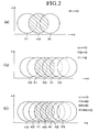
- Figures 2 (a) through (c) are schematic diagrams for explaining the relationship between the recording position of the hologram and the phase code.
- Figures 2 (a), (b), and (c) respectively show cases where shift multiplexing of 2, 3 and 4-multiplicity is performed in the Y direction.
- the phase code pattern of the hologram H1 is preferably orthogonal to that of the hologram H0.
- the phase code pattern of the hologram H1 is preferably orthogonal to that of the hologram H0.
- phase code pattern of the hologram H2 which overlaps with the hologram H0 through the intervening hologram H1, that is, the next adjacent hologram H1, is preferably different from that of the hologram H0.
- the correlation of the phase codes is set lower as the overlap of the holograms is larger.
- the degree of the correlation of the phase code patterns of the holograms H1 and H2 relative to the hologram H0 is set so that H1 ⁇ H2.
- the phase code pattern of the hologram H1 is preferably orthogonal to that of the hologram H0.
- phase code pattern of the hologram H2 which overlaps the hologram H0 through the intervening hologram H1, that is, the next adjacent hologram H1, is preferably different from that of the hologram H0.
- phase code pattern of the hologram H3 which overlaps the hologram H0 through the intervening holograms H1 and H2, is preferably different from that of the hologram H0.
- the correlation of the phase codes is set lower as the overlap of the holograms is larger.
- the degree of the correlation of the phase code patterns of the hologram H1, H2 and H3 relative to the hologram H0 is set so that H1 ⁇ H2 ⁇ H3.
- FIG. 3 is a flowchart showing the sequence of steps in the foregoing multiplex recording.
- phase codes of first through nth patterns are used in order and thus the holograms are recorded in order (S302 - S305).
- the rotation of the phase codes is based on the degree of multiplexing of the phase shift multiplexing and the like. Since the pattern of the phase code changes at each recording of a hologram, the same phase code pattern is therefore never used at least at adjacent holograms.
- the holographic is finished when the information runs out (S303Y).
- Figure 4 is a schematic diagram of the method of holographic recording in one preferred embodiment of the present invention.
- the holographic recording device 400 comprises an optical pickup 110 for generating beams projected onto the disk 490, a focusing and tracking servo mechanism 420 for controlling focusing and tracking of the optical pickup 420, a signal processor 430 for processing signals from the optical pickup 110, a spindle servo mechanism 440 for controlling rotation of the disk 490, and a controller 450 for controlling the different members.
- the pickup 110 is arranged so that the track direction of the disk 490 is the X direction and the radial direction of the disk 490 is the Y direction.
- the spindle servo mechanism 440 rotates the disk 490.
- Holograms are recorded sequentially in the track direction (the X direction) and are therefore recorded along a spiral from the inner circumference to the outer circumference, or from the outer circumference to the inner circumference.
- Shift multiplexing in the track direction is realized by overlapping part of adjacent holograms along the Y direction, and shift multiplexing in the radial direction (the Y direction) is realized by overlapping part of adjacent holograms recorded in adjacent tracks.
- shift multiplexing in the radial direction is realized by setting the track pitch smaller and overlapping not only adjacent holograms recorded on the same track but also holograms recorded on adjacent tracks.
- shift multiplexing can be performed in the track direction and the radial direction, and the shift multiplexing and the phase code multiplex recording are used together in the radial direction. That is, phase code multiplex recording is performed with the same phase code pattern in the same track, and phase code multiplex recording is performed in the next track with a different phase code pattern from that used in the last track.
- phase code patterns overlapping each other in the radial direction are made different.
- the correlation of the phase codes is set lower as the overlap of the holograms is higher, and an orthogonal phase code pattern is preferably used.
- Figure 5 is a schematic plan view showing an arrangement of the holograms on the disk.
- holograms are recorded sequentially by the shift multiplexing on first track T1 with a first phase code C1.
- the spots of the signal beam and the reference beam are shifted in the radial direction (the Y direction) and holograms are recorded sequentially on the next track T2 with a second phase code C2.
- a second phase code whose pattern is orthogonal to that of the first phase code is used.
- phase code Holograms imparted with a phase code are also recorded in the track direction. However, since only one phase code pattern is used, the recording does not function substantially as phase code multiplex recording and only the shift multiplexing is realized.
- the shift multiplexing and the phase code multiplex recording are used together by changing the phase code pattern at every track. It is therefore possible to improve the degree of multiplexing of the shift multiplexing.
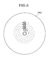
- Figure 6 is a schematic diagram showing an example of the distribution of phase codes on the disk.
- the holograms are recorded in a spiral pattern from the inner circumference to the outer circumference of the disk 490.
- phase code C1 In the innermost first track, information is recorded with the phase code C1. In second track, information is recorded with the phase code C2 orthogonal to the phase code C1. In third track, information is recorded with the phase code C1 again. In subsequent tracks, holograms are recorded using phase codes C1 and C2 by turns.
- phase codes are never used for holograms that overlap in the radial direction. Accordingly, it is possible to improve the degree of multiplexing of the shift multiplexing in the radial direction in which Bragg selectivity is low. If the track pitch is set narrower, it is possible to increase the recording density.
- Figure 7 is a schematic diagram showing another example of the distribution of phase codes on the disk.
- the holograms are recorded in a spiral pattern from the inner circumference to the outer circumference on the disk.
- phase code C1 In the innermost first track, information is recorded with the phase code C1. In second track, information is recorded with the phase code C2 orthogonal to the phase code C1. In third track, information is recorded with the phase code C3 orthogonal to both phase codes C1 and C2. In subsequent tracks, holograms are recorded using the phase codes C1, C2 and C3 by turns.
- the same phase is never used for holograms that overlap in the radial direction. Accordingly, it is possible to improve the degree of multiplexing of the shift multiplexing in the radial direction in which Bragg selectivity is low. If the track pitch is set narrower, it is possible to increase the recording density.
- Figure 8 is a schematic diagram showing another example of the distribution of phase codes on the disk.
- holograms are recorded in a spiral pattern from the inner circumference to the outer circumference of the disk 490.
- a number of phase code patterns are used in the same track.
- phase codes C4, C5 and C6 In the innermost first track, information is recorded with the phase codes C4, C5 and C6.
- holograms are recorded by repeating the foregoing.
- the same phase code is never used for holograms that overlap in the radial direction. Accordingly, it is possible to improve degree of multiplexing of the shift multiplexing in the radial direction in which Bragg selectivity is low. If the track pitch is set narrower, it is possible to increase the recording density.
- the recording method is not limited to that of changing the phase code at every track and it is possible instead to change the code each time a prescribed number of holograms is recorded or each time holograms are recorded a prescribed number of times.
- Figure 9 is a schematic diagram showing another example of the distribution of phase codes on the disk.
- the holograms are recorded in a spiral pattern from the inner circumference to the outer circumference of the disk 490.
- multiplex recording of holograms is conducted using phase codes C1-C10 of ten patterns with respect to a disk in which the number of holograms recordable at the outermost nth track is 5 fold the number of holograms recordable at the innermost first track.
- the maximum recording number (k) of holograms at the first track located at the inner circumference is defined as the limit for changing the phase code, and the phase is changed to the next in order each time recording of (k) number of holograms is completed.
- information is recorded in the first track with the phase code C1.
- Information is recorded in the second track with the phase code C2.
- Information is then recorded from near the end of the second track to the third track with the phase code C3, and recorded from near the end of the third track to the fourth track with the phase code C4.
- Such sequential recording of information is continued until, for example, holograms are recorded in the (n-1)th track with the phase codes C1-C5 and in the nth track with the phase codes C6-C10.
- the holograms are recorded with the several phase codes having patterns orthogonal to each other in order.
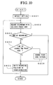
- Figure 10 is a flowchart showing the sequence of steps in multiplex recording on the above disk.
- default settings are selected for a predetermined recording position and first pattern of the phase code (S901), after which a first hologram is recorded at the recording position with this phase code (S902).
- the recording position is shifted in the track direction (S904N, S905), after which a second hologram is recorded with a phase code of the same pattern as that of used for the immediately preceding hologram (S902).
- holograms are sequentially recorded (S902 - S905) and the phase code is changed to the next pattern at the predetermined time point for changing the phase code (S904Y, S906).
- the predetermined time point is the time point at which a predetermined number of the holograms has been recorded, the time point at which holograms have been recorded a predetermined number of times, or the time point at which the recording of holograms in a track has been completed.
- holograms are recorded by repeatedly using several phase code patterns by turns.
- the present invention it is possible to improve selectivity along the radial direction (the Y direction) by using the phase code multiplex recording in combination with the shift multiplexing in the radial direction. It is therefore possible to improve the degree of multiplexing in the radial direction and to increase the recording density.
- FIG 11 is a schematic diagram showing the holographic recording in accordance with another preferred embodiment of the present invention. Components that are the same as those shown in Figure 1 are assigned the same reference symbols and explanation thereof will be omitted.
- a holographic recording device 900 comprises an optical pickup 110, a focusing and tracking servo mechanism 320, a signal processor 330 and a controller 350.
- the optical pickup 110 is set up so that the track direction, i.e., the longitudinal direction of the card type recording medium 990, is set in the X direction and the width direction orthogonal to the longitudinal direction is set in the Y direction. Then the optical pickup 110 is driven in the X and Y direction by the focusing and tracking servo mechanism 320. Thus holograms are two-dimensionally recorded in the X and Y directions.
- shift multiplexing in the track direction (the X direction) is realized by partially overlapping adjacent holograms in the track direction
- shift multiplexing in the width direction is realized by partially overlapping at least adjacent holograms in the width direction.
- the degree of multiplexing of the holographic recording can be arbitrarily set.
- shift multiplexing can be performed in the track direction and the width direction and the shift multiplexing and the phase code multiplex recording are used together in the width direction. That is, the phase code multiplex recording is performed with same phase code pattern in same track, and in the next track, the phase code multiplex recording is performed with a different phase code pattern from that used in last track.
- the phase code patterns overlapping each other in the radial direction are made different.
- the correlation of the phase codes is set lower as the overlap of the holograms is higher, and an orthogonal phase code pattern is preferably used.
- the present invention it is possible to improve selectivity in the width direction (the Y direction) by using phase code multiplex recording in combination with the shift multiplexing in the radial direction. It is therefore possible to improve the degree of multiplexing in the width direction and to increase the recording density.
- the above embodiments were explained with respect to disc-type and card-type recording media.
- the recording medium is not particularly limited and any of various types of recording media can be selected.
Landscapes
- Physics & Mathematics (AREA)
- General Physics & Mathematics (AREA)
- Holo Graphy (AREA)
- Optical Recording Or Reproduction (AREA)
- Optical Head (AREA)
Abstract
Description
Claims (11)
- A holographic recording method for recording information as phase information of light by projecting a signal beam and a reference beam onto a recording medium, wherein an X direction is defined as the direction of a line of intersection between a plane including the optical axes of the signal beam and reference beam (incidence plane) and the recording plane of the recording medium, and the Y direction is defined as the direction of a line lying normal to the incidence plane and intersecting said line of intersection, comprising steps of;
using the reference beam modulated with a first phase code to record a first hologram at a predetermined position; and
using the reference beam modulated with a second phase code whose pattern is different from that of the first phase code to record at a position shifted in the Y direction a second hologram that partially overlaps the first hologram. - A holographic recording method in accordance with Claim 1 further comprising a step of using the reference beam modulated with a third phase code whose pattern is different from that of the first and second phase codes to record at a position shifted in the Y direction a third hologram that partially overlaps the first and second holograms,
wherein a correlation between the third phase code and the second phase code being set lower than a correlation between the third phase code and the first phase code. - A holographic recording method in accordance with Claim 1 or 2 including a step of using the reference beam modulated with the first phase code to record at position shifted to the X direction a fourth hologram that partially overlaps the first hologram.
- A holographic recording method for recording information as phase information of light by projecting a signal beam and a reference beam onto a recording medium, wherein an X direction is defined as the direction of a line of intersection between a plane including the optical axes of the signal beam and reference beam (incidence plane) and the recording plane of the recording medium, and the Y direction is defined as the direction of a line lying normal to the incidence plane and intersecting said line of intersection, comprising a step of recording holograms by shift multiplexing at least in the Y direction and using phase code multiplexing in combination with the shift code multiplexing in the Y direction.
- A holographic recording method in accordance with Claim 4, wherein the phase codes used in the phase code multiplexing have lower correlation with increasing overlap between two holograms recorded by shift multiplexing in the Y direction.
- A holographic recording method in accordance with Claim 4 or 5, wherein orthogonal phase codes are used for holograms adjacent along the Y direction.
- A holographic recording method in accordance with any one of Claims 4 to 6, wherein the holograms are recorded along both the X direction and Y direction by shift multiplexing.
- A holographic recording method in accordance with Claim 7, wherein the same phase code is used for holograms recorded along the X direction.
- A holographic recording method in accordance with Claim 7, wherein two or more different phase codes are used for holograms recorded along the X direction.
- A holographic recording method in accordance with any one of Claims 4 to 9, wherein the recording medium is a disk, and the X direction and Y direction are the tracking direction and the radial direction of the disk, respectively.
- A holographic recording device for recording information as phase information of light by projecting a signal beam and a reference beam onto a recording medium comprising:wherein,a laser beam source;a beam splitter for dividing the beam from the laser beam source;a spatial light modulator for generating a signal beam containing information by modulating the intensity of one divided beam;a phase spatial light modulator for generating a reference beam by modulating the phase of the other divided beam with a predetermined phase code;a controller for controlling the incidence position of the signal beam and reference beam on the recording medium;
an X direction is defined as the direction of a line of intersection between an incidence plane including the optical axes of the signal beam and reference beam and the recording plane of the recording medium,
a Y direction is defined as the direction of a line perpendicular to the incidence plane,
and the controller records holograms by shift multiplexing at least in the Y direction and using phase code multiplexing in combination with the shift multiplexing in the Y direction.
Applications Claiming Priority (2)
| Application Number | Priority Date | Filing Date | Title |
|---|---|---|---|
| JP2003013914A JP4097533B2 (en) | 2003-01-22 | 2003-01-22 | Hologram recording method and apparatus |
| JP2003013914 | 2003-01-22 |
Publications (2)
| Publication Number | Publication Date |
|---|---|
| EP1441263A2 true EP1441263A2 (en) | 2004-07-28 |
| EP1441263A3 EP1441263A3 (en) | 2004-08-04 |
Family
ID=32588646
Family Applications (1)
| Application Number | Title | Priority Date | Filing Date |
|---|---|---|---|
| EP04001200A Withdrawn EP1441263A3 (en) | 2003-01-22 | 2004-01-21 | A method and device for multiplex holographic recording |
Country Status (4)
| Country | Link |
|---|---|
| US (1) | US7362687B2 (en) |
| EP (1) | EP1441263A3 (en) |
| JP (1) | JP4097533B2 (en) |
| CN (1) | CN1280801C (en) |
Cited By (4)
| Publication number | Priority date | Publication date | Assignee | Title |
|---|---|---|---|---|
| KR100759493B1 (en) | 2006-11-08 | 2007-09-18 | 주식회사 대우일렉트로닉스 | Optical information processing device and optical information processing method |
| KR100767932B1 (en) | 2006-04-06 | 2007-10-18 | 주식회사 대우일렉트로닉스 | Optical information reproducing device, tracking servo control device and tracking control method |
| KR100846573B1 (en) | 2006-11-08 | 2008-07-15 | 주식회사 대우일렉트로닉스 | Optical information processing device and optical information processing method |
| EP2387034A3 (en) * | 2010-05-07 | 2011-11-30 | General Electric Company | System and method for improved data storage |
Families Citing this family (22)
| Publication number | Priority date | Publication date | Assignee | Title |
|---|---|---|---|---|
| JP2003337523A (en) * | 2002-05-17 | 2003-11-28 | Pioneer Electronic Corp | Hologram recording device and hologram reconstructing device |
| WO2005078717A1 (en) * | 2004-02-18 | 2005-08-25 | Samsung Electronics Co., Ltd. | Hologram recording medium |
| JP4294526B2 (en) * | 2004-03-26 | 2009-07-15 | 独立行政法人科学技術振興機構 | Digital holography apparatus and image reproduction method using digital holography |
| TWI274336B (en) * | 2004-04-14 | 2007-02-21 | Samsung Electronics Co Ltd | Hologram memory medium, apparatus and method of recording and/or reproducing information with respect to the hologram memory medium |
| US7202919B2 (en) * | 2004-07-13 | 2007-04-10 | Imation Corp. | Holographic data storage with PDLC spatial light modulator generating reference and object beams |
| JP2006030380A (en) * | 2004-07-13 | 2006-02-02 | Sony Corp | Hologram apparatus and hologram recording method |
| JP4543843B2 (en) * | 2004-09-10 | 2010-09-15 | ソニー株式会社 | Hologram recording method, hologram recording apparatus, hologram reproducing apparatus, and hologram recording medium |
| JP4634122B2 (en) * | 2004-11-26 | 2011-02-16 | 日本放送協会 | Holographic optical memory recording apparatus and recording / reproducing apparatus |
| EP1701341A1 (en) * | 2005-03-07 | 2006-09-13 | Deutsche Thomson-Brandt Gmbh | Holographic recording medium and pickup for this medium |
| JP2006323291A (en) * | 2005-05-20 | 2006-11-30 | Sony Corp | Recording medium, playback device, and playback method |
| JP4734530B2 (en) * | 2005-09-09 | 2011-07-27 | 新オプトウエア株式会社 | retrieval method |
| WO2007049336A1 (en) * | 2005-10-25 | 2007-05-03 | Fujitsu Limited | Hologram recording device |
| EP1850337A3 (en) * | 2006-04-25 | 2008-01-23 | Daewoo Electronics Corporation | Optical information processing apparatus, optical information recording method, optical information reproducing method and optical information servo controlling method |
| EP1918913A1 (en) * | 2006-10-31 | 2008-05-07 | Thomson Holding Germany GmbH & Co. OHG | Method for producing a security mark on an optical data carrier |
| EP1921614A3 (en) * | 2006-11-08 | 2008-06-11 | Daewoo Electronics Corporation | Optical information processing apparatus and optical information processing method |
| US7986603B1 (en) * | 2007-09-29 | 2011-07-26 | Silicon Light Machines Corporation | Spatial light modulator for holographic data storage |
| US8182966B2 (en) * | 2008-12-23 | 2012-05-22 | General Electric Company | Data storage devices and methods |
| JP4573186B2 (en) * | 2009-04-15 | 2010-11-04 | 日本ビクター株式会社 | Optical information reproducing method, optical information reproducing apparatus, optical information recording / reproducing apparatus, and optical information reproducing program |
| US8314938B2 (en) * | 2010-07-30 | 2012-11-20 | Canon Kabushiki Kaisha | Method and apparatus for measuring surface profile of an object |
| KR102067762B1 (en) * | 2013-03-20 | 2020-02-11 | 삼성전자주식회사 | Method and apparatus for holographic recording |
| KR101863718B1 (en) * | 2016-04-14 | 2018-06-01 | 나길호 | Method of manufacturing the Transparent type hologram label |
| US10788670B2 (en) * | 2016-07-01 | 2020-09-29 | Intel Corporation | Method to manufacture lens having embedded holographic optical element for near eye display |
Family Cites Families (13)
| Publication number | Priority date | Publication date | Assignee | Title |
|---|---|---|---|---|
| US4018503A (en) | 1973-02-01 | 1977-04-19 | Daniel Silverman | Holographic systems having reference beam coded holograms |
| US5319629A (en) * | 1988-08-25 | 1994-06-07 | Sparta, Inc. | Content addressable optical data storage system |
| US5627664A (en) * | 1994-06-29 | 1997-05-06 | Tamarack Storage Devices, Inc. | Holographic storage with combined orthogonal phase codes and random phase codes |
| US5978112A (en) * | 1995-02-15 | 1999-11-02 | California Institute Of Technology | Non-volatile readout of shift multiplexed holograms |
| US5671073A (en) * | 1995-02-15 | 1997-09-23 | California Institute Of Technology | Holographic storage using shift multiplexing |
| US5719691A (en) * | 1995-05-05 | 1998-02-17 | Lucent Technologies Inc. | Phase correlation multiplex holography |
| CA2172643C (en) * | 1995-05-05 | 2000-02-15 | Kevin Curtis | Multiplex holography |
| US5808998A (en) * | 1995-12-27 | 1998-09-15 | Lucent Technologies Inc | Bit error rate reduction by reducing the run length of same-state pixels in a halographic process |
| US5877873A (en) * | 1996-07-24 | 1999-03-02 | Bashaw; Matthew C. | Differential video image compression in holographic media |
| US6614566B1 (en) * | 2000-06-07 | 2003-09-02 | Lucent Technologies Inc. | Process for holography involving skip-sorted hologram storage |
| US6958967B2 (en) * | 2000-11-17 | 2005-10-25 | Matsushita Electric Industrial Co., Ltd. | Holographic optical information recording/reproducing device |
| US6697180B1 (en) * | 2002-08-09 | 2004-02-24 | Inphase Technologies, Inc. | Rotation correlation multiplex holography |
| US7092133B2 (en) * | 2003-03-10 | 2006-08-15 | Inphase Technologies, Inc. | Polytopic multiplex holography |
-
2003
- 2003-01-22 JP JP2003013914A patent/JP4097533B2/en not_active Expired - Lifetime
-
2004
- 2004-01-16 US US10/759,452 patent/US7362687B2/en not_active Expired - Fee Related
- 2004-01-20 CN CN200410002498.1A patent/CN1280801C/en not_active Expired - Fee Related
- 2004-01-21 EP EP04001200A patent/EP1441263A3/en not_active Withdrawn
Cited By (4)
| Publication number | Priority date | Publication date | Assignee | Title |
|---|---|---|---|---|
| KR100767932B1 (en) | 2006-04-06 | 2007-10-18 | 주식회사 대우일렉트로닉스 | Optical information reproducing device, tracking servo control device and tracking control method |
| KR100759493B1 (en) | 2006-11-08 | 2007-09-18 | 주식회사 대우일렉트로닉스 | Optical information processing device and optical information processing method |
| KR100846573B1 (en) | 2006-11-08 | 2008-07-15 | 주식회사 대우일렉트로닉스 | Optical information processing device and optical information processing method |
| EP2387034A3 (en) * | 2010-05-07 | 2011-11-30 | General Electric Company | System and method for improved data storage |
Also Published As
| Publication number | Publication date |
|---|---|
| US20040145994A1 (en) | 2004-07-29 |
| JP4097533B2 (en) | 2008-06-11 |
| CN1280801C (en) | 2006-10-18 |
| US7362687B2 (en) | 2008-04-22 |
| JP2004227658A (en) | 2004-08-12 |
| CN1527293A (en) | 2004-09-08 |
| EP1441263A3 (en) | 2004-08-04 |
Similar Documents
| Publication | Publication Date | Title |
|---|---|---|
| US7362687B2 (en) | Method and device for holographic recording | |
| JP3924549B2 (en) | Hologram recording / reproducing method and apparatus | |
| JP4778924B2 (en) | Optical information processing apparatus and optical information processing method | |
| US7706233B2 (en) | Optical-disk recording method, recording apparatus and reproducing apparatus | |
| JP3946181B2 (en) | Holographic digital data recording system | |
| JP7144553B2 (en) | Hologram disc reading method and apparatus capable of high-speed parallel reproduction | |
| JP2006162928A (en) | Hologram recording apparatus and hologram recording method | |
| JP2018137031A (en) | Hologram recording / reproducing method and hologram recording / reproducing apparatus | |
| US8472298B2 (en) | Optical information recording and reproducing apparatus and optical information recording method | |
| US20070268539A1 (en) | Apparatus and method for holographic recording and reproducing | |
| JP2005148700A (en) | Holographic recording apparatus, holographic reconstructing apparatus, and mask | |
| JP2005310308A (en) | Hologram recording / reproducing apparatus and hologram recording / reproducing method | |
| JP4346608B2 (en) | Information recording apparatus and information recording / reproducing apparatus | |
| JP2003085768A (en) | Optical information recording apparatus and method | |
| JP2005032308A (en) | Optical information storage method | |
| JP2010181760A (en) | Optical information recording method and recording device | |
| US20070223070A1 (en) | Holographic Master Production and Replication | |
| JP2003178457A (en) | Optical disk recording method, optical disk recording device, and optical disk reproducing device | |
| JP2006172582A (en) | Hologram recording device | |
| KR20100002150A (en) | Recording apparatus and recording method | |
| JP2009020134A (en) | Hologram element, hologram element manufacturing apparatus, hologram element manufacturing method, and hologram reproducing apparatus | |
| JP4197450B2 (en) | Information recording apparatus, information reproducing apparatus, information recording method, information reproducing method, and information recording medium | |
| JP2007280583A (en) | Optical information processing apparatus, and optical information recording and reproducing method using the same | |
| JP2006243243A (en) | Hologram recording / reproducing apparatus and hologram recording method | |
| JP2010044843A (en) | Recording and reproducing device, recording device, reproducing device, recording and reproducing method, recording method, and reproducing method |
Legal Events
| Date | Code | Title | Description |
|---|---|---|---|
| PUAI | Public reference made under article 153(3) epc to a published international application that has entered the european phase |
Free format text: ORIGINAL CODE: 0009012 |
|
| PUAL | Search report despatched |
Free format text: ORIGINAL CODE: 0009013 |
|
| AK | Designated contracting states |
Kind code of ref document: A2 Designated state(s): AT BE BG CH CY CZ DE DK EE ES FI FR GB GR HU IE IT LI LU MC NL PT RO SE SI SK TR |
|
| AX | Request for extension of the european patent |
Extension state: AL LT LV MK |
|
| AK | Designated contracting states |
Kind code of ref document: A3 Designated state(s): AT BE BG CH CY CZ DE DK EE ES FI FR GB GR HU IE IT LI LU MC NL PT RO SE SI SK TR |
|
| AX | Request for extension of the european patent |
Extension state: AL LT LV MK |
|
| 17P | Request for examination filed |
Effective date: 20041022 |
|
| 17Q | First examination report despatched |
Effective date: 20041206 |
|
| AKX | Designation fees paid |
Designated state(s): DE FR GB NL |
|
| RBV | Designated contracting states (corrected) |
Designated state(s): DE FR GB NL |
|
| STAA | Information on the status of an ep patent application or granted ep patent |
Free format text: STATUS: THE APPLICATION IS DEEMED TO BE WITHDRAWN |
|
| 18D | Application deemed to be withdrawn |
Effective date: 20130812 |