EP1441195A1 - Displacement sensor - Google Patents
Displacement sensor Download PDFInfo
- Publication number
- EP1441195A1 EP1441195A1 EP02720499A EP02720499A EP1441195A1 EP 1441195 A1 EP1441195 A1 EP 1441195A1 EP 02720499 A EP02720499 A EP 02720499A EP 02720499 A EP02720499 A EP 02720499A EP 1441195 A1 EP1441195 A1 EP 1441195A1
- Authority
- EP
- European Patent Office
- Prior art keywords
- excitation coil
- coil
- frequency
- detecting
- probe
- Prior art date
- Legal status (The legal status is an assumption and is not a legal conclusion. Google has not performed a legal analysis and makes no representation as to the accuracy of the status listed.)
- Withdrawn
Links
Images


Classifications
-
- G—PHYSICS
- G01—MEASURING; TESTING
- G01D—MEASURING NOT SPECIALLY ADAPTED FOR A SPECIFIC VARIABLE; ARRANGEMENTS FOR MEASURING TWO OR MORE VARIABLES NOT COVERED IN A SINGLE OTHER SUBCLASS; TARIFF METERING APPARATUS; MEASURING OR TESTING NOT OTHERWISE PROVIDED FOR
- G01D5/00—Mechanical means for transferring the output of a sensing member; Means for converting the output of a sensing member to another variable where the form or nature of the sensing member does not constrain the means for converting; Transducers not specially adapted for a specific variable
- G01D5/12—Mechanical means for transferring the output of a sensing member; Means for converting the output of a sensing member to another variable where the form or nature of the sensing member does not constrain the means for converting; Transducers not specially adapted for a specific variable using electric or magnetic means
- G01D5/14—Mechanical means for transferring the output of a sensing member; Means for converting the output of a sensing member to another variable where the form or nature of the sensing member does not constrain the means for converting; Transducers not specially adapted for a specific variable using electric or magnetic means influencing the magnitude of a current or voltage
- G01D5/20—Mechanical means for transferring the output of a sensing member; Means for converting the output of a sensing member to another variable where the form or nature of the sensing member does not constrain the means for converting; Transducers not specially adapted for a specific variable using electric or magnetic means influencing the magnitude of a current or voltage by varying inductance, e.g. by a movable armature
- G01D5/2006—Mechanical means for transferring the output of a sensing member; Means for converting the output of a sensing member to another variable where the form or nature of the sensing member does not constrain the means for converting; Transducers not specially adapted for a specific variable using electric or magnetic means influencing the magnitude of a current or voltage by varying inductance, e.g. by a movable armature by influencing the self-induction of one or more coils
- G01D5/2013—Mechanical means for transferring the output of a sensing member; Means for converting the output of a sensing member to another variable where the form or nature of the sensing member does not constrain the means for converting; Transducers not specially adapted for a specific variable using electric or magnetic means influencing the magnitude of a current or voltage by varying inductance, e.g. by a movable armature by influencing the self-induction of one or more coils by a movable ferromagnetic element, e.g. a core
-
- G—PHYSICS
- G01—MEASURING; TESTING
- G01D—MEASURING NOT SPECIALLY ADAPTED FOR A SPECIFIC VARIABLE; ARRANGEMENTS FOR MEASURING TWO OR MORE VARIABLES NOT COVERED IN A SINGLE OTHER SUBCLASS; TARIFF METERING APPARATUS; MEASURING OR TESTING NOT OTHERWISE PROVIDED FOR
- G01D5/00—Mechanical means for transferring the output of a sensing member; Means for converting the output of a sensing member to another variable where the form or nature of the sensing member does not constrain the means for converting; Transducers not specially adapted for a specific variable
- G01D5/12—Mechanical means for transferring the output of a sensing member; Means for converting the output of a sensing member to another variable where the form or nature of the sensing member does not constrain the means for converting; Transducers not specially adapted for a specific variable using electric or magnetic means
- G01D5/14—Mechanical means for transferring the output of a sensing member; Means for converting the output of a sensing member to another variable where the form or nature of the sensing member does not constrain the means for converting; Transducers not specially adapted for a specific variable using electric or magnetic means influencing the magnitude of a current or voltage
- G01D5/20—Mechanical means for transferring the output of a sensing member; Means for converting the output of a sensing member to another variable where the form or nature of the sensing member does not constrain the means for converting; Transducers not specially adapted for a specific variable using electric or magnetic means influencing the magnitude of a current or voltage by varying inductance, e.g. by a movable armature
- G01D5/204—Mechanical means for transferring the output of a sensing member; Means for converting the output of a sensing member to another variable where the form or nature of the sensing member does not constrain the means for converting; Transducers not specially adapted for a specific variable using electric or magnetic means influencing the magnitude of a current or voltage by varying inductance, e.g. by a movable armature by influencing the mutual induction between two or more coils
- G01D5/2046—Mechanical means for transferring the output of a sensing member; Means for converting the output of a sensing member to another variable where the form or nature of the sensing member does not constrain the means for converting; Transducers not specially adapted for a specific variable using electric or magnetic means influencing the magnitude of a current or voltage by varying inductance, e.g. by a movable armature by influencing the mutual induction between two or more coils by a movable ferromagnetic element, e.g. a core
-
- G—PHYSICS
- G01—MEASURING; TESTING
- G01D—MEASURING NOT SPECIALLY ADAPTED FOR A SPECIFIC VARIABLE; ARRANGEMENTS FOR MEASURING TWO OR MORE VARIABLES NOT COVERED IN A SINGLE OTHER SUBCLASS; TARIFF METERING APPARATUS; MEASURING OR TESTING NOT OTHERWISE PROVIDED FOR
- G01D2205/00—Indexing scheme relating to details of means for transferring or converting the output of a sensing member
- G01D2205/70—Position sensors comprising a moving target with particular shapes, e.g. of soft magnetic targets
- G01D2205/77—Specific profiles
- G01D2205/775—Tapered profiles
Definitions
- the present invention relates to a displacement sensor.
- the microactuator In order to control operation of a microactuator of a manipulator or the like used in a micromachine or gene manipulation, it is requested that the microactuator is small-sized and light-weighed for detecting and measuring a displacement amount of a moving object by a resolution of from micrometer to nanometer.
- various systems in detecting and measuring a displacement amount by the resolution of from micrometer to nanometer, various systems have been proposed and reduced into practice.
- laser measurement by a method of irradiating an object with laser light and detecting a phase difference brought about in accordance with displacement of the object, a method of using a phenomenon of interference between the laser light and reference light or the like.
- a displacement amount in a nanometer order can be measured by using laser measurement technology or the like.
- a size of a microactuator is in an order of from several centimeters to ten and several centimeters
- a light source, a measuring portion for detecting and measuring a phase difference or interference and the like become considerably large-sized.
- the apparatus becomes expensive since a complicated optical system and a measuring frequency at a high frequency are used and the like in order to promote the resolution.
- a displacement sensor is characterized in comprising an excitation coil and a detection coil arranged in a predetermined positional relationship, an amplifier an input end of which is connected to an output end of the detection coil, a phase shifting circuit provided between an output end of the amplifier and an input end of the excitation coil for shifting to nullify a phase difference by changing a frequency when the phase difference is produced between an input waveform inputted to the excitation coil and an output waveform outputted from the detection coil, frequency measuring means for detecting a frequency deviation produced by shifting the phase, and a rod-like probe of a magnetic body which is inserted into at least one of air core portions of the excitation coil and the detection coil and a sectional area of which is changed in a longitudinal direction for detecting a displacement amount of an object to be measured from the frequency deviation produced by displacing the rod-like probe in the longitudinal axis direction while maintaining a resonating state of a closed loop including a space between the excitation coil and the detection
- the displacement sensor according to the invention is characterized in that the excitation coil is constituted by connecting two coils wound such that polarities thereof are directed reverse to each other in series.
- a displacement sensor is characterized in comprising a light emitting element for making light incident on an object to be measured, a light receiving element for detecting a reflected wave from the object to be measured, an amplifier an input end of which is connected to an output end of the light receiving element, a phase shifting circuit provided between an output end of the amplifier and an input end of the light emitting element for shifting to nullify a phase difference by changing a frequency when the phase difference is produced between an input waveform inputted to the light emitting element and an output waveform outputted from the light receiving element, and frequency measuring means for detecting a frequency deviation produced by shifting the phase for detecting a displacement of the object to be measured from the frequency deviation produced by displacing the object to be measured while maintaining a resonance of a closed loop including a space between the light emitting element and the light receiving element.
- the displacement sensor according to the invention is constructed by a constitution in which a detection coil, an amplifier, a phase shifting circuit and an excitation coil are connected in this order and a rod-like probe of a magnetic body a sectional area of which is changed in a longitudinal axis direction is arranged to be inserted into at least one of air core portions of the detection coil and the excitation coil.
- a frequency deviation is produced in accordance with a displacement amount while maintaining a resonating state of a closed loop including a space between the excitation coil and the detection coil and therefore, the displacement amount of the rod-like probe can be detected.
- a displacement sensor capable of detecting the displacement amount by a resolution of 0.1 through 0.01 micrometer, detecting and measuring a displacement amount of a moving object by a resolution in a micrometer to nanometer order by a simple structure and suitable for small-sized and light-weighted formation.
- the excitation coil is constituted by connecting two coils wound such that polarities thereof are directed reverse to each other in series.
- magnetic fields thereof are canceled by each other at a vicinity of a point of connecting the two coils and when the two coils are provided with the same characteristic, a substantially nullified magnetic field is constituted to balance.
- a displacement sensor for detecting and measuring the displacement amount of the moving object by a resolution at a micrometer level by a simple structure and suitable for small-sized and light-weighted formation.
- a displacement sensor is constructed by a constitution in which a light emitting element and a light receiving element are used, light is made to be incident on an object to be measured, a reflected wave therefrom is detected and the light receiving element, an amplifier, a phase shifting circuit and the light emitting element are connected in this order.
- a frequency deviation is produced in accordance with the displacement amount while maintaining a resonating state of a closed loop including a space between the light emitting element and the light receiving element and therefore, the displacement amount of the object to be measured can be detected.
- a displacement sensor for detecting and measuring the displacement amount of the moving object by a resolution in a micrometer through nanometer order by a simple structure and suitable for small-sized and light-weighted formation.
- Fig. 1 is a view showing a constitution of a displacement sensor 1 of an inductance directly measuring type according to a first embodiment.
- the displacement sensor 1 is constituted by a coil 3, a probe 5 of a magnetic body in a conical shape a sectional area of which is changed in a longitudinal axis direction, an inductance meter 7 arranged between two terminals of the coil 3 and a displacement conversion portion 9 for converting a detected value of the inductance meter 7 into a displacement amount.
- the probe 5 of the magnetic body is arranged to be inserted into an air core portion of the coil 3.
- inductance of the coil 3 is changed. That is, it is generally known that inductance of a coil having a permeability ⁇ of an air core portion, a sectional area A, a length L in a longitudinal direction and a turn number N is proportional to ⁇ *A*N*N/L.
- the sectional area of which is changed in the longitudinal direction is displaced in the longitudinal direction (x) at inside of the air core portion of the coil 3, in accordance with a displacement amount thereof, a volume of the probe disposed in the air core portion of the coil 3 is changed, ⁇ is substantially changed and the inductance is changed.
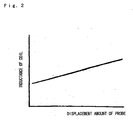
- Fig. 2 is a diagram designating the abscissa by the displacement amount of the probe 5 and designating the ordinate by the inductance of the coil 3 and showing a relationship therebetween.
- a direction of increasing the displacement amount is a direction of increasing the volume of the probe 5 of the magnetic body disposed at the air core portion of the coil 3.
- ⁇ is substantially increased and the inductance of the coil 3 is also increased.
- the displacement amount of the probe 5 can be provided by a simple structure by displacing the probe 5 of the magnetic body the sectional area of which is changed in the longitudinal direction at inside of the area core portion, detecting the change in the inductance of the coil 3 at that occasion by the inductance meter 7 and converting a detected value thereof into the displacement amount by the displacement amount conversion portion.
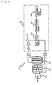
- Fig. 3 is a block diagram of a displacement sensor 21 of an inductance type according to a second embodiment.
- An excitation coil 23 and a detection coil 25 are arranged by aligning longitudinal axes of respective air core portions thereof commonly. Further, a probe 27 in a conical shape a sectional area of which is changed in a longitudinal direction is provided and the probe 27 is constituted by a magnetic body. Further, the probe 27 is arranged in a state of being inserted into the air core portion of the excitation coil 23.
- An output terminal from the detection coil 25 and an input terminal to the excitation coil 23 are connected to a signal processing portion 31.
- the output terminal from the detection coil 25 is connected to an amplifier 33 and a phase shifting circuit 35 is provided between the amplifier 33 and the input terminal of the excitation coil 23.
- a frequency deviation detector 37 is connected to the phase shifting circuit 35, further, a displacement amount calculator 39 is connected to the frequency deviation detector 37.
- a phase difference is produced between an input signal inputted to the excitation coil 23 and an output signal outputted from the detection coil 25 and the phase shifting circuit 35 changes a frequency to nullify the phase difference.
- a frequency deviation at the occasion is detected by the frequency deviation detector 37 and the displacement amount is outputted by the displacement calculator 39 for processing a relationship between the frequency deviation and the displacement amount.
- a frequency deviation equal to or larger than several 10 kHz is produced by a displacement amount of 1mm and therefore, the displacement amount can be detected by a resolution at a micrometer level. Since the frequency deviation is in an order of several 10 kHz, a processing frequency of the signal processing portion is comparatively low and the signal processing portion can be constructed by a simple circuit constitution.
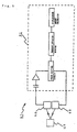
- Fig. 4 shows a displacement sensor 22 of an inductance type having a higher sensitivity according to a third embodiment.
- the same notations are attached to constituent elements common to those of Fig. 3 and an explanation thereof will be omitted.
- coils 24a and 24b wound such that pluralities thereof are directed reverse to each other and connected in series for an excitation coil 24. According to the constitution, magnetic fields are canceled by each other at a vicinity of a point of connecting the two coils 24a and 24b and when the two coils 24a and 24b are provided with the same characteristic, a substantially nullified magnetic field is constituted to balance.
- a change in the balance by inserting the probe 27 of the magnetic body can be detected by a detection coil 26 and a sensitivity with respect to a displacement is further increased.
- a displacement sensor for detecting and measuring a displacement amount of a moving object by a resolution at a micrometer level and suitable for small-sized and light-welded formation by a simple structure.
- a positional relationship between the excitation coil and the detection coil may be established by an arranging method by which a constant positional relationship is fixed by arranging the excitation coil and the detection coil to align longitudinal axes of respective air core portions thereof commonly as in Fig. 3, arranging the detection coil concentrically at an outer periphery of the excitation coil as in Fig. 4 or the like.
- the probe may be arranged by being inserted into at least one of the air core portions of the excitation coil and the detection coil.
- Other than a conical shape, other shape by which a sectional area thereof is changed such as a portion of a cone, a function body of rotation constituting an axis of rotation by a longitudinal axis thereof, a portion of a pyramid or the like can be used for the probe.
- Fig. 5 is a block diagram of a displacement sensor 51 of an optical type according to a fourth embodiment.
- a light emitting element 53 and a light receiving element 55 are provided to be opposed to an object 57 to be measured.
- An output terminal from the light receiving element 55 and an input terminal to the light emitting element 53 are connected to the signal processing portion 31.
- Constitution and operation of the signal processing portion 31 are similar to those of Fig. 2 and therefore, an explanation thereof will be omitted.
- a single closed loop resonating circuit is formed by including a space between the light emitting element 53 and the light receiving element 55, that is, a path of light of the light emitting element 53 - the object 57 to be measured - the light receiving element 55.
- a frequency deviation equal to or larger than 100kHz through 1000kHz is produced by a displacement amount of 1mm, the displacement amount can be detected by a resolution in a nanometer order. Since the frequency deviation is utilized, a processing frequency of the signal processing portion can be produced by a comparatively simple circuit constitution.
- a displacement sensor for detecting and measuring a displacement amount of a moving object by a resolution of from micrometer to nanometer and suitable for small-sized and light-weighted formation by simple constitutions of the light emitting element, the light receiving element and the signal processing portion having a comparatively low processing frequency.
- the displacement sensor according to the invention can detect and measure the displacement amount of the moving object by the resolution of from micrometer to nanometer by a simple structure and is suitable for small-sized and light-weighted formation.
Landscapes
- Physics & Mathematics (AREA)
- General Physics & Mathematics (AREA)
- Measurement Of Length, Angles, Or The Like Using Electric Or Magnetic Means (AREA)
- Transmission And Conversion Of Sensor Element Output (AREA)
- Length Measuring Devices By Optical Means (AREA)
- Optical Transform (AREA)
- Optical Radar Systems And Details Thereof (AREA)
Abstract
Description
Claims (3)
- A displacement sensor characterized in comprising an excitation coil and a detection coil arranged in a predetermined positional relationship, an amplifier an input end of which is connected to an output end of the detection coil, a phase shifting circuit provided between an output end of the amplifier and an input end of the excitation coil for shifting to nullify a phase difference by changing a frequency when the phase difference is produced between an input waveform inputted to the excitation coil and an output waveform outputted from the detection coil, frequency measuring means for detecting a frequency deviation produced by shifting the phase, and a rod-like probe of a magnetic body which is inserted into at least one of air core portions of the excitation coil and the detection coil and a sectional area of which is changed in a longitudinal direction for detecting a displacement amount of an object to be measured from the frequency deviation produced by displacing the rod-like probe in the longitudinal axis direction while maintaining a resonating state of a closed loop including a space between the excitation coil and the detection coil.
- The displacement sensor according to Claim 1, characterized in that the excitation coil is constituted by connecting two coils wound such that polarities thereof are directed reverse to each other in series.
- A displacement sensor characterized in comprising a light emitting element for making light incident on an object to be measured, a light receiving element for detecting a reflected wave from the object to be measured, an amplifier an input end of which is connected to an output end of the light receiving element, a phase shifting circuit provided between an output end of the amplifier and an input end of the light emitting element for shifting to nullify a phase difference by changing a frequency when the phase difference is produced between an input waveform inputted to the light emitting element and an output waveform outputted from the light receiving element, and frequency measuring means for detecting a frequency deviation produced by shifting the phase for detecting a displacement of the object to be measured from the frequency deviation produced by displacing the object to be measured while maintaining a resonance of a closed loop including a space between the light emitting element and the light receiving element.
Applications Claiming Priority (3)
| Application Number | Priority Date | Filing Date | Title |
|---|---|---|---|
| JP2001333299 | 2001-10-30 | ||
| JP2001333299A JP3888427B2 (en) | 2001-10-30 | 2001-10-30 | Displacement sensor |
| PCT/JP2002/003884 WO2003038371A1 (en) | 2001-10-30 | 2002-04-18 | Displacement sensor |
Publications (2)
| Publication Number | Publication Date |
|---|---|
| EP1441195A1 true EP1441195A1 (en) | 2004-07-28 |
| EP1441195A4 EP1441195A4 (en) | 2006-11-29 |
Family
ID=19148592
Family Applications (1)
| Application Number | Title | Priority Date | Filing Date |
|---|---|---|---|
| EP02720499A Withdrawn EP1441195A4 (en) | 2001-10-30 | 2002-04-18 | Displacement sensor |
Country Status (6)
| Country | Link |
|---|---|
| US (2) | US7007554B2 (en) |
| EP (1) | EP1441195A4 (en) |
| JP (1) | JP3888427B2 (en) |
| CN (1) | CN1227510C (en) |
| TW (1) | TW567306B (en) |
| WO (1) | WO2003038371A1 (en) |
Families Citing this family (22)
| Publication number | Priority date | Publication date | Assignee | Title |
|---|---|---|---|---|
| JP3888427B2 (en) * | 2001-10-30 | 2007-03-07 | 学校法人日本大学 | Displacement sensor |
| US7249528B2 (en) * | 2002-05-17 | 2007-07-31 | Jtekt Corporation | Hub unit with sensor |
| JP4348467B2 (en) * | 2003-09-30 | 2009-10-21 | 学校法人日本大学 | Biological material property inspection system using light |
| JP2007123470A (en) * | 2005-10-27 | 2007-05-17 | Fujitsu Component Ltd | Solenoid actuator and 2-axis actuator |
| JP5051525B2 (en) * | 2007-06-05 | 2012-10-17 | 学校法人日本大学 | Displacement measurement system |
| DE102007033751A1 (en) * | 2007-07-19 | 2009-01-22 | Cherry Gmbh | Arrangement of a coil pair in a local measuring range |
| JP4742108B2 (en) | 2008-02-05 | 2011-08-10 | 株式会社コナミデジタルエンタテインメント | Game system, jackpot lottery device and game device constituting the same |
| CN102176060B (en) * | 2011-01-25 | 2012-11-14 | 中国人民解放军国防科学技术大学 | Inductance approach switch sensor |
| CN103115634B (en) * | 2013-03-05 | 2015-07-08 | 上海兰宝传感科技股份有限公司 | Multi-coil material distinguishing inductive transducer |
| CN103175551B (en) * | 2013-03-05 | 2015-06-24 | 上海兰宝传感科技股份有限公司 | Inductive sensor with attenuation coefficient which is one |
| US20150008906A1 (en) * | 2013-07-03 | 2015-01-08 | Dennis K. Briefer | Position sensing device |
| DE102014218754A1 (en) * | 2014-09-18 | 2016-03-24 | Continental Teves Ag & Co. Ohg | Magnetic sensor, sensor arrangement and method for determining the position of a magnetically active element |
| CN104776791B (en) * | 2015-04-16 | 2018-09-07 | 日立楼宇技术(广州)有限公司 | A kind of method of displacement sensor and measurement displacement |
| CN105928449B (en) * | 2016-04-28 | 2018-07-17 | 西安交通大学 | A kind of data processing method of inductive displacement transducer |
| CN106767952B (en) * | 2017-02-28 | 2018-12-07 | 西安交通大学 | A kind of interference elimination method of inductive displacement transducer |
| EP3385758A1 (en) * | 2017-04-05 | 2018-10-10 | HILTI Aktiengesellschaft | Device and method for detecting electrically conductive measurement objects in a base |
| WO2019220953A1 (en) * | 2018-05-15 | 2019-11-21 | 株式会社島津製作所 | Magnetic body inspection device and magnetic body inspection method |
| EP3683537A1 (en) | 2019-01-18 | 2020-07-22 | Fundació Institut Català de Nanociència i Nanotecnologia | Displacement sensor |
| US11360200B2 (en) * | 2019-04-02 | 2022-06-14 | Tennessee Technological University | Omnidirectional, electric near-field distance sensing device |
| CN112525061B (en) * | 2020-11-09 | 2022-09-13 | 西南科技大学 | Wireless strain testing device and method adopting nano composite material |
| CN114993150B (en) * | 2022-05-27 | 2026-04-14 | 北京无线电计量测试研究所 | Measurement system and method for resolving multiple position information by single-channel alternating current signal |
| CN120846181B (en) * | 2025-09-24 | 2025-11-21 | 中国科学技术大学 | A non-contact inductive displacement sensor based on a planar bent coil |
Family Cites Families (27)
| Publication number | Priority date | Publication date | Assignee | Title |
|---|---|---|---|---|
| US3513408A (en) * | 1968-08-01 | 1970-05-19 | Tri Metrics | Displacement transducer oscillator with movable tapered magnetic core |
| US3891918A (en) * | 1971-03-23 | 1975-06-24 | James F Ellis | Linear displacement transducer utilizing an oscillator whose average period varies as a linear function of the displacement |
| JPS5491355A (en) * | 1977-12-28 | 1979-07-19 | Nippon Chemical Ind | Device for measuring displacement |
| FR2468877A1 (en) * | 1979-11-05 | 1981-05-08 | Snecma | LINEAR DISPLACEMENT SENSOR |
| FR2549596B1 (en) * | 1983-07-20 | 1987-09-18 | Europ Propulsion | DISPLACEMENT MEASUREMENT METHOD AND SENSOR |
| JPS60155570U (en) * | 1984-03-26 | 1985-10-16 | 株式会社瑞穂製作所 | Movement amount detection device |
| JPS62276402A (en) * | 1986-05-23 | 1987-12-01 | Omron Tateisi Electronics Co | Linear output type position sensor |
| JPS6421305U (en) * | 1987-07-30 | 1989-02-02 | ||
| JPH0299312A (en) | 1988-10-07 | 1990-04-11 | Asahi Chem Ind Co Ltd | Manufacture of polyoxymethylene hollow material |
| US5075545A (en) * | 1988-10-26 | 1991-12-24 | United Technologies Corporation | Optical measurement of the position of an object |
| JPH0754810Y2 (en) * | 1989-01-26 | 1995-12-18 | 日東工器株式会社 | Displacement measuring device |
| JPH0797009B2 (en) * | 1989-12-29 | 1995-10-18 | 株式会社荏原製作所 | Inductance type displacement sensor |
| US5206587A (en) * | 1990-03-30 | 1993-04-27 | Mitchell Rose | Inductive displacement transducer having telescoping probe assembly |
| JP2914037B2 (en) * | 1991-09-30 | 1999-06-28 | キヤノン株式会社 | Speckle interferometer |
| US5394233A (en) * | 1993-04-06 | 1995-02-28 | Wang; Charles P. | Apparatus for measuring high frequency vibration, motion, or displacement |
| JPH07332911A (en) * | 1994-06-03 | 1995-12-22 | Sony Corp | Sensor for axis position detection |
| JP3151153B2 (en) * | 1995-09-20 | 2001-04-03 | 定夫 尾股 | Frequency deviation detection circuit and measuring instrument using the same |
| US5767670A (en) * | 1996-08-29 | 1998-06-16 | Texas Instruments Incorporated | Method and apparatus for providing improved temperature compensated output for variable differential transformer system |
| US5777468A (en) * | 1996-12-19 | 1998-07-07 | Texas Instruments Incorporated | Variable differential transformer system and method providing improved temperature stability and sensor fault detection apparatus |
| US6052190A (en) | 1997-09-09 | 2000-04-18 | Utoptics, Inc. | Highly accurate three-dimensional surface digitizing system and methods |
| CH693188A5 (en) * | 1999-03-11 | 2003-03-27 | Csem Ct Suisse D Electronique Sa | optimized inductive sensor. |
| WO2000065299A2 (en) * | 1999-04-23 | 2000-11-02 | Scientific Generics Limited | Position sensor |
| CN1483136A (en) * | 2000-11-30 | 2004-03-17 | 阿赛勒姆研究股份有限公司 | Improved Linear Variable Differential Transformer for High Accuracy Position Measurement |
| US6583618B2 (en) * | 2001-09-21 | 2003-06-24 | Framatome, Anp Inc. | Remote magnetic field material analyzer and method |
| JP3888427B2 (en) * | 2001-10-30 | 2007-03-07 | 学校法人日本大学 | Displacement sensor |
| US6967574B1 (en) * | 2003-01-21 | 2005-11-22 | The Johns Hopkins University | Multi-mode electromagnetic target discriminator sensor system and method of operation thereof |
| US7078906B2 (en) * | 2003-09-23 | 2006-07-18 | The Johns Hopkins University | Simultaneous time-domain and frequency-domain metal detector |
-
2001
- 2001-10-30 JP JP2001333299A patent/JP3888427B2/en not_active Expired - Fee Related
-
2002
- 2002-04-18 US US10/476,304 patent/US7007554B2/en not_active Expired - Fee Related
- 2002-04-18 CN CNB028062124A patent/CN1227510C/en not_active Expired - Fee Related
- 2002-04-18 EP EP02720499A patent/EP1441195A4/en not_active Withdrawn
- 2002-04-18 WO PCT/JP2002/003884 patent/WO2003038371A1/en not_active Ceased
- 2002-05-28 TW TW091111275A patent/TW567306B/en not_active IP Right Cessation
-
2005
- 2005-07-12 US US11/178,564 patent/US7281432B2/en not_active Expired - Fee Related
Also Published As
| Publication number | Publication date |
|---|---|
| CN1227510C (en) | 2005-11-16 |
| US20040123677A1 (en) | 2004-07-01 |
| US7281432B2 (en) | 2007-10-16 |
| EP1441195A4 (en) | 2006-11-29 |
| US7007554B2 (en) | 2006-03-07 |
| US20050247134A1 (en) | 2005-11-10 |
| JP3888427B2 (en) | 2007-03-07 |
| WO2003038371A1 (en) | 2003-05-08 |
| CN1496474A (en) | 2004-05-12 |
| JP2003139562A (en) | 2003-05-14 |
| TW567306B (en) | 2003-12-21 |
Similar Documents
| Publication | Publication Date | Title |
|---|---|---|
| US7281432B2 (en) | Displacement sensor with an excitation coil and a detection coil | |
| US6192753B1 (en) | Inductive sensor for monitoring fluid level and displacement | |
| CN101387709B (en) | Inductive proximity detector with switched windings | |
| EP2082192B1 (en) | Linear displacement sensor | |
| EP1067391A1 (en) | Current sensor | |
| US5712563A (en) | Steering torque sensor utilizing a displacement detector having a pulse power supply | |
| EP4064374A1 (en) | Magnetic sensor | |
| KR950003207B1 (en) | Metal body discriminating apparatus | |
| EP1762859B1 (en) | Signal detection circuit of magnetic sensor | |
| US5446379A (en) | Method and system for searching and sensing reinforcing steel in concrete by employing an oscillator driver sensor coil | |
| KR20070030130A (en) | Excitation coil drive circuit of magnetic sensor | |
| US5194805A (en) | Inductance-type displacement sensor for eliminating inaccuracies due to external magnetic fields | |
| US7605585B2 (en) | Air-core transformer position sensor | |
| US6571642B1 (en) | Magnetic flow sensor with annular sensing path | |
| US8947074B1 (en) | Inductive position sensor | |
| EP1612576A1 (en) | NMR shim coils | |
| US5541503A (en) | Alternating current sensor based on concentric-pipe geometry and having a transformer for providing separate self-powering | |
| US20110133727A1 (en) | Inductive Position Sensor | |
| KR102908794B1 (en) | Fuel rod sensor system with inductive coupling | |
| WO2014158498A1 (en) | Two-dimensional inductive position sensing system | |
| CN219915761U (en) | High-precision wide-range current sensor | |
| EP4443181A1 (en) | Magnetic sensor and magnetic field measurement device using the same | |
| KR100361167B1 (en) | A measurement system for initial permeability | |
| CA1130471A (en) | Asymmetrical squid | |
| SU1620844A1 (en) | Device for measuring flow rate of liquid and gaseous media |
Legal Events
| Date | Code | Title | Description |
|---|---|---|---|
| PUAI | Public reference made under article 153(3) epc to a published international application that has entered the european phase |
Free format text: ORIGINAL CODE: 0009012 |
|
| 17P | Request for examination filed |
Effective date: 20031023 |
|
| AK | Designated contracting states |
Kind code of ref document: A1 Designated state(s): AT BE CH CY DE DK ES FI FR GB GR IE IT LI LU MC NL PT SE TR |
|
| RIC1 | Information provided on ipc code assigned before grant |
Ipc: 7G 01B 11/00 B Ipc: 7G 01D 5/20 B Ipc: 7G 01B 7/00 A |
|
| A4 | Supplementary search report drawn up and despatched |
Effective date: 20050218 |
|
| RA4 | Supplementary search report drawn up and despatched (corrected) |
Effective date: 20060904 |
|
| RIC1 | Information provided on ipc code assigned before grant |
Ipc: G01B 11/00 20060101ALI20061009BHEP Ipc: G01D 5/20 20060101ALI20061009BHEP Ipc: G01B 7/00 20060101AFI20030513BHEP Ipc: G01D 5/30 20060101ALI20061009BHEP Ipc: G01L 9/00 20060101ALI20061009BHEP |
|
| RA4 | Supplementary search report drawn up and despatched (corrected) |
Effective date: 20061012 |
|
| RA4 | Supplementary search report drawn up and despatched (corrected) |
Effective date: 20061030 |
|
| STAA | Information on the status of an ep patent application or granted ep patent |
Free format text: STATUS: THE APPLICATION HAS BEEN WITHDRAWN |
|
| 18W | Application withdrawn |
Effective date: 20090428 |