EP1441150A2 - Ratcheting hydraulic chain tensioner with rotational reset and locking means - Google Patents
Ratcheting hydraulic chain tensioner with rotational reset and locking means Download PDFInfo
- Publication number
- EP1441150A2 EP1441150A2 EP04250072A EP04250072A EP1441150A2 EP 1441150 A2 EP1441150 A2 EP 1441150A2 EP 04250072 A EP04250072 A EP 04250072A EP 04250072 A EP04250072 A EP 04250072A EP 1441150 A2 EP1441150 A2 EP 1441150A2
- Authority
- EP
- European Patent Office
- Prior art keywords
- piston
- chain
- pawl
- flat
- ratchet teeth
- Prior art date
- Legal status (The legal status is an assumption and is not a legal conclusion. Google has not performed a legal analysis and makes no representation as to the accuracy of the status listed.)
- Withdrawn
Links
Images


Classifications
-
- F—MECHANICAL ENGINEERING; LIGHTING; HEATING; WEAPONS; BLASTING
- F16—ENGINEERING ELEMENTS AND UNITS; GENERAL MEASURES FOR PRODUCING AND MAINTAINING EFFECTIVE FUNCTIONING OF MACHINES OR INSTALLATIONS; THERMAL INSULATION IN GENERAL
- F16H—GEARING
- F16H7/00—Gearings for conveying rotary motion by endless flexible members
- F16H7/08—Means for varying tension of belts, ropes or chains
-
- F—MECHANICAL ENGINEERING; LIGHTING; HEATING; WEAPONS; BLASTING
- F16—ENGINEERING ELEMENTS AND UNITS; GENERAL MEASURES FOR PRODUCING AND MAINTAINING EFFECTIVE FUNCTIONING OF MACHINES OR INSTALLATIONS; THERMAL INSULATION IN GENERAL
- F16H—GEARING
- F16H7/00—Gearings for conveying rotary motion by endless flexible members
- F16H7/08—Means for varying tension of belts, ropes or chains
- F16H7/0848—Means for varying tension of belts, ropes or chains with means for impeding reverse motion
-
- F—MECHANICAL ENGINEERING; LIGHTING; HEATING; WEAPONS; BLASTING
- F16—ENGINEERING ELEMENTS AND UNITS; GENERAL MEASURES FOR PRODUCING AND MAINTAINING EFFECTIVE FUNCTIONING OF MACHINES OR INSTALLATIONS; THERMAL INSULATION IN GENERAL
- F16H—GEARING
- F16H7/00—Gearings for conveying rotary motion by endless flexible members
- F16H7/08—Means for varying tension of belts, ropes or chains
- F16H2007/0802—Actuators for final output members
- F16H2007/0806—Compression coil springs
-
- F—MECHANICAL ENGINEERING; LIGHTING; HEATING; WEAPONS; BLASTING
- F16—ENGINEERING ELEMENTS AND UNITS; GENERAL MEASURES FOR PRODUCING AND MAINTAINING EFFECTIVE FUNCTIONING OF MACHINES OR INSTALLATIONS; THERMAL INSULATION IN GENERAL
- F16H—GEARING
- F16H7/00—Gearings for conveying rotary motion by endless flexible members
- F16H7/08—Means for varying tension of belts, ropes or chains
- F16H2007/0802—Actuators for final output members
- F16H2007/0812—Fluid pressure
-
- F—MECHANICAL ENGINEERING; LIGHTING; HEATING; WEAPONS; BLASTING
- F16—ENGINEERING ELEMENTS AND UNITS; GENERAL MEASURES FOR PRODUCING AND MAINTAINING EFFECTIVE FUNCTIONING OF MACHINES OR INSTALLATIONS; THERMAL INSULATION IN GENERAL
- F16H—GEARING
- F16H7/00—Gearings for conveying rotary motion by endless flexible members
- F16H7/08—Means for varying tension of belts, ropes or chains
- F16H7/0848—Means for varying tension of belts, ropes or chains with means for impeding reverse motion
- F16H2007/0853—Ratchets
-
- F—MECHANICAL ENGINEERING; LIGHTING; HEATING; WEAPONS; BLASTING
- F16—ENGINEERING ELEMENTS AND UNITS; GENERAL MEASURES FOR PRODUCING AND MAINTAINING EFFECTIVE FUNCTIONING OF MACHINES OR INSTALLATIONS; THERMAL INSULATION IN GENERAL
- F16H—GEARING
- F16H7/00—Gearings for conveying rotary motion by endless flexible members
- F16H7/08—Means for varying tension of belts, ropes or chains
- F16H2007/0876—Control or adjustment of actuators
- F16H2007/0878—Disabling during transport
Definitions
- the present invention relates generally to tensioners used with chain drives in automotive timing and power transmission applications.
- the present invention is related to a hydraulic chain tensioner system.
- a tensioning device such as a hydraulic tensioner, is used as a control device for a power transmission chain, or similar power transmission devices, as the chain travels between a plurality of sprockets.
- the chain transmits power from a driving shaft to a driven shaft, so that part of the chain is slack and part of the chain is tight.
- it is important to impart and maintain a certain degree of tension in the chain to prevent noise, slippage, or the unmeshing of teeth in the case of a toothed chain.
- Prevention of such slippage is particularly important in the case of a chain driven camshaft in an internal combustion engine because jumping of teeth will throw off the camshaft timing, possibly causing damage or rendering the engine inoperative.
- hydraulic tensioners is a common method of maintaining proper chain tension.
- these mechanisms employ a lever arm that pushes against the chain on the slack side of the power transmission system. This lever arm must push toward the chain, tightening the chain when the chain is slack, and must be very rigid when the chain tightens.
- a hydraulic tensioner typically comprises a rod or cylinder as a piston, which is biased in the direction of the chain by a tensioner spring.
- the piston is housed within a cylindrical housing, having an interior space which is open at the end facing the chain and closed at the other end.
- the interior space of the housing contains a pressure chamber in connection with a reservoir or exterior source of hydraulic fluid pressure.
- the pressure chamber is typically formed between the housing and the piston, and it expands or contracts when the piston moves within the housing.
- a block tensioner (1) as known in the prior art is shown in Fig. 1.
- the tensioner (1) has a piston (2) located within a housing (5).
- the springs (3) are located in a fluid chamber (4) within the piston (2).
- the tensioner (1) also includes a pawl (6) and ratchet teeth (7).
- a hydraulic chain or belt tensioner includes a ratchet-pawl interface on the piston skirt that can be reset to a locked position by rotating the piston and compressing it until locked.
- the tensioner preferably includes at least one flat on the piston. The flat prevents the piston from rotating axially and locks the piston into place. The locked position is especially useful for shipping the tensioner.
- the hydraulic piston tensioner (10) of the present invention has a ratcheting interface between a piston skirt (11) and a pawl (12).
- the tensioner spring (23) biases the piston (15) in the direction of the chain (not shown).
- the piston (15) is located within a housing (24).
- the ratcheting interface between the piston skirt (11) and the pawl (12) contains teeth (22) shaped to allow the piston (15) to extend as the slope of the teeth forces the pawl (12) away from the piston (15) and against its spring (13). Opposing faces of the teeth (22) prevent the piston's compression.
- the teeth (22) are recessed into the skirt (11) sufficiently to provide a shoulder (14) on which the pawl (12) will impact at a predetermined piston position. Even if the teeth are not engaged, the pawl (12) prevents further extension of the piston (15).
- the pawl (12) is located and constrained by a pawl spring (13), a retaining ring (16), and a series of surfaces formed in the cylinder (33) surrounding the piston (15).
- the pawl spring (13) urges the pawl to remain in contact with the ratchet teeth (22) or the piston skirt (11), depending upon axial orientation of the piston (15). If the piston (15) is absent for any reason, such as during servicing, a pair of flats (30) in the cylinder (33) prevent the pawl (12) from overextending. During continued service, the same flats (30) act to prevent rotation of the piston (15) within the cylinder bore.
- the retaining ring (16) limits the pawl position in the extending piston axial direction.
- a shoulder (32) in the cylinder (33) limits the position of the pawl (12) in the opposite axial direction, allowing a specified clearance (20) distance for axial pawl motion.
- the area of the pawl (12) contacting the shoulder (14) of the skirt (11) is enhanced by providing that the adjacent tooth of the pawl (12) is less than a full tooth.
- the shoulder (32) is preferably generated by removing a circular segment from the side of the cylinder (33), which creates an opening (31) through the wall. In the figures, the shoulder (32) is illustrated as coinciding with the open end of the cylinder (33), but this is not required.
- the clearance (20) allows the required piston backlash.
- the pawl (12) is carried along by the piston (15) until the retaining ring (16) stops it.
- the piston's teeth (22) then ratchet with the pawl's teeth (17) until the chain stops the piston's (15) extension. Locking the assembly in this state and then changing the thermal environment, for example in a running engine versus a cold engine, can result in a tightening chain trying to compress the piston (15). This is permitted by the clearance (backlash) (20) between the pawl (12) and the piston's cylinder along the piston's axis.
- the piston skirt (11) includes a flat (18) with a depth similar to the ratchet teeth (22) and a length (19) equal to or longer than the thickness (26) of the pawl (12) when measured along the piston's axis. In one embodiment, this flat (18) is at a sufficient spacing (27) from the teeth (22) to allow some piston skirt (11) to exist between them, although this is not required.
- the flat (18) is preferably positioned axially with the top of the teeth (22) or lower. The actual axial location of the flat (18) is preferably determined by the optimum position of the locked piston (15) during installation.
- the piston (15) also preferably includes a hole (21) or flat(s) (28) to facilitate rotation.
- the hole (21) is accessible when the piston (15) is compressed to the locked depth (whether locked or ratcheted), as well as when the piston (15) is extended and tensioning the chain or belt.
- the pawl (12) is released from the flat (18).
- the tensioner (10) can be released and the piston (15) compressed by simply rotating the piston (15) to disengage the ratchet teeth (22).
- the piston (15) can be rotated, so that its flat (18) is in alignment with the pawl (12), and then the piston (15) is locked in the shipping position simply by compressing the piston (15) until latched. Reverse rotation releases the piston (15) into the ratcheting mode.
- the pawl spring (13) resists accidental rotation.
Landscapes
- Engineering & Computer Science (AREA)
- General Engineering & Computer Science (AREA)
- Mechanical Engineering (AREA)
- Devices For Conveying Motion By Means Of Endless Flexible Members (AREA)
Abstract
A hydraulic chain or belt tensioner (10) includes a ratchet-pawl interface on the piston
skirt (11) that can be reset to a locked position by rotating the piston (11) and compressing it until
locked. The tensioner preferably includes at least one flat (30) on the piston (11). The flat (30) prevents
the piston (11) from rotating axially and locks the piston into place. The locked position is
especially useful for shipping the tensioner (10).
Description
- The present invention relates generally to tensioners used with chain drives in automotive timing and power transmission applications. In particular, the present invention is related to a hydraulic chain tensioner system.
- A tensioning device, such as a hydraulic tensioner, is used as a control device for a power transmission chain, or similar power transmission devices, as the chain travels between a plurality of sprockets. In this device, the chain transmits power from a driving shaft to a driven shaft, so that part of the chain is slack and part of the chain is tight. Generally, it is important to impart and maintain a certain degree of tension in the chain to prevent noise, slippage, or the unmeshing of teeth in the case of a toothed chain. Prevention of such slippage is particularly important in the case of a chain driven camshaft in an internal combustion engine because jumping of teeth will throw off the camshaft timing, possibly causing damage or rendering the engine inoperative.
- However, in the harsh environment of an internal combustion engine, various factors can cause fluctuations in the chain tension. For instance, wide variations in temperature and thermal expansion coefficients among the various parts of the engine can cause the chain tension to vary between excessively high or low levels. During prolonged use, wear to the components of the power transmission system can cause a decrease in chain tension. In addition, camshaft and crankshaft induced torsional vibrations cause considerable variations in chain tensions. Reverse rotation of an engine, occurring for example in stopping or in failed attempts at starting, can also cause fluctuations in chain tension. For these reasons, a mechanism is desired to remove excessive tensioning forces on the tight side of the chain and to ensure the necessary tension on the slack side of the chain.
- Using hydraulic tensioners is a common method of maintaining proper chain tension. In general, these mechanisms employ a lever arm that pushes against the chain on the slack side of the power transmission system. This lever arm must push toward the chain, tightening the chain when the chain is slack, and must be very rigid when the chain tightens.
- To accomplish this result, a hydraulic tensioner typically comprises a rod or cylinder as a piston, which is biased in the direction of the chain by a tensioner spring. The piston is housed within a cylindrical housing, having an interior space which is open at the end facing the chain and closed at the other end. The interior space of the housing contains a pressure chamber in connection with a reservoir or exterior source of hydraulic fluid pressure. The pressure chamber is typically formed between the housing and the piston, and it expands or contracts when the piston moves within the housing.
- Blade and block tensioners have been used in the past to apply tension to chains. A block tensioner (1) as known in the prior art is shown in Fig. 1. The tensioner (1) has a piston (2) located within a housing (5). The springs (3) are located in a fluid chamber (4) within the piston (2). The tensioner (1) also includes a pawl (6) and ratchet teeth (7).
- A hydraulic chain or belt tensioner includes a ratchet-pawl interface on the piston skirt that can be reset to a locked position by rotating the piston and compressing it until locked. The tensioner preferably includes at least one flat on the piston. The flat prevents the piston from rotating axially and locks the piston into place. The locked position is especially useful for shipping the tensioner.
-
- Fig. 1
- shows a cross sectional view of a prior art block tensioner with a ratchet mechanism.
- Fig. 2
- shows a cross sectional view of the tensioner of the present invention in a compressed but unlocked state.
- Fig. 3
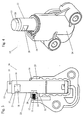
- shows a partial section of the tensioner of the present invention where the piston is fully extended and unlocked, showing a hole for engaging a pin or other tool to rotate the piston.
- Fig. 4
- shows an isometric view of Fig. 3, showing the locking flat and optional flat(s) for engaging a tool to rotate the piston.
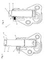
- Fig. 5
- shows a partial section of the tensioner of the present invention, where the piston is rotated to align locking flat and pawl.
- Fig. 6
- shows a partial section of the tensioner of the present invention, where the piston is compressed into the locked position.
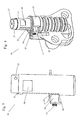
- Fig. 7
- shows a side view of the tensioner of the present invention with the cylinder and housing removed, where the piston is extended, and the pawl teeth are disengaged from the piston teeth to show that the shoulders still overlap.
- Fig. 8
- shows a partial section of the tensioner of the present invention, where the piston is extended in the ratcheting mode to illustrate how the pawl interfaces with the retaining ring and the cylinder's flat and shoulder.
- Fig. 9
- shows a view of Fig. 8, with the piston and pawl removed.
- Referring to Figs. 2 through 9, the hydraulic piston tensioner (10) of the present invention has a ratcheting interface between a piston skirt (11) and a pawl (12). The tensioner spring (23) biases the piston (15) in the direction of the chain (not shown). The piston (15) is located within a housing (24).
- The ratcheting interface between the piston skirt (11) and the pawl (12) contains teeth (22) shaped to allow the piston (15) to extend as the slope of the teeth forces the pawl (12) away from the piston (15) and against its spring (13). Opposing faces of the teeth (22) prevent the piston's compression. The teeth (22) are recessed into the skirt (11) sufficiently to provide a shoulder (14) on which the pawl (12) will impact at a predetermined piston position. Even if the teeth are not engaged, the pawl (12) prevents further extension of the piston (15).
- The pawl (12) is located and constrained by a pawl spring (13), a retaining ring (16), and a series of surfaces formed in the cylinder (33) surrounding the piston (15). The pawl spring (13) urges the pawl to remain in contact with the ratchet teeth (22) or the piston skirt (11), depending upon axial orientation of the piston (15). If the piston (15) is absent for any reason, such as during servicing, a pair of flats (30) in the cylinder (33) prevent the pawl (12) from overextending. During continued service, the same flats (30) act to prevent rotation of the piston (15) within the cylinder bore.
- The retaining ring (16) limits the pawl position in the extending piston axial direction. A shoulder (32) in the cylinder (33) limits the position of the pawl (12) in the opposite axial direction, allowing a specified clearance (20) distance for axial pawl motion. In a preferred embodiment, the area of the pawl (12) contacting the shoulder (14) of the skirt (11) is enhanced by providing that the adjacent tooth of the pawl (12) is less than a full tooth. The shoulder (32) is preferably generated by removing a circular segment from the side of the cylinder (33), which creates an opening (31) through the wall. In the figures, the shoulder (32) is illustrated as coinciding with the open end of the cylinder (33), but this is not required.
- The clearance (20) allows the required piston backlash. The pawl (12) is carried along by the piston (15) until the retaining ring (16) stops it. The piston's teeth (22) then ratchet with the pawl's teeth (17) until the chain stops the piston's (15) extension. Locking the assembly in this state and then changing the thermal environment, for example in a running engine versus a cold engine, can result in a tightening chain trying to compress the piston (15). This is permitted by the clearance (backlash) (20) between the pawl (12) and the piston's cylinder along the piston's axis.
- In a preferred embodiment, the piston skirt (11) includes a flat (18) with a depth similar to the ratchet teeth (22) and a length (19) equal to or longer than the thickness (26) of the pawl (12) when measured along the piston's axis. In one embodiment, this flat (18) is at a sufficient spacing (27) from the teeth (22) to allow some piston skirt (11) to exist between them, although this is not required. The flat (18) is preferably positioned axially with the top of the teeth (22) or lower. The actual axial location of the flat (18) is preferably determined by the optimum position of the locked piston (15) during installation.
- The piston (15) also preferably includes a hole (21) or flat(s) (28) to facilitate rotation. The hole (21) is accessible when the piston (15) is compressed to the locked depth (whether locked or ratcheted), as well as when the piston (15) is extended and tensioning the chain or belt. When the piston (15) is rotated, using the flat (28) or hole for purchase, the pawl (12) is released from the flat (18).
- When the piston (15) is extended and incompressible due to ratchet interface, the tensioner (10) can be released and the piston (15) compressed by simply rotating the piston (15) to disengage the ratchet teeth (22). The piston (15) can be rotated, so that its flat (18) is in alignment with the pawl (12), and then the piston (15) is locked in the shipping position simply by compressing the piston (15) until latched. Reverse rotation releases the piston (15) into the ratcheting mode. The pawl spring (13) resists accidental rotation.
- Accordingly, it is to be understood that the embodiments of the invention herein described are merely illustrative of the application of the principles of the invention. Reference herein to details of the illustrated embodiments is not intended to limit the scope of the claims, which themselves recite those features regarded as essential to the invention.
Claims (10)
- A chain or belt tensioner comprising:wherein when the piston is rotated from a first position where the ratchet teeth engage the pawl and a second position where the pawl rests in the flat, the piston is restrained from axial movement.a) a piston comprising:i) a plurality of ratchet teeth along a length of a piston skirt comprising an outer layer of the piston; andii) at least one flat with a depth similar to a depth of the ratchet teeth, wherein the flat is positioned rotationally around a circumference of the piston away from the ratchet teeth; andb) a pawl comprising a spring and a plurality of ratchet teeth, wherein the spring forces the ratchet teeth of the pawl against the ratchet teeth of the piston;
- The chain or belt tensioner of claim 1, wherein a thickness of the pawl is less or equal to a length of the flat when measured along an axis of the piston.
- The chain or belt tensioner of claim 1 or 2, wherein the ratchet teeth of the piston ratchet with the ratchet teeth of the pawl until a chain stops an extension of the piston.
- The chain or belt tensioner of claim 1, 2 or 3, further comprising a shoulder along a side of the piston skirt, wherein the pawl is retained along the axis of the piston by the shoulder.
- The chain or belt tensioner of any one of claims 1 to 4, further comprising a retaining ring around a perimeter of the piston skirt, wherein the retaining ring retains the pawl along the axis of the piston.
- The chain or belt tensioner of any one of claims 1 to 5, wherein the flat is oriented radially at a sufficient angle from the first plurality of ratchet teeth to allow a portion of the piston skirt to exist between the flat and the first plurality of ratchet teeth.
- The chain or belt tensioner of any one of claims 1 to 6, wherein an axial location of the flat is determined by an optimum position of the locked piston during installation.
- The chain or belt tensioner of any one of claims 1 to 7, wherein the piston further comprises at least one flat for rotation of the piston.
- The chain or belt tensioner of any one of claims 1 to 8, wherein the piston further comprises at least one hole for rotation of the piston.
- The chain or belt tensioner of any one of claims 1 to 9, wherein when the piston is restrained from axial movement, the piston is in a locked position.
Applications Claiming Priority (2)
| Application Number | Priority Date | Filing Date | Title |
|---|---|---|---|
| US350517 | 2003-01-24 | ||
| US10/350,517 US6852049B2 (en) | 2003-01-24 | 2003-01-24 | Ratcheting hydraulic chain tensioner with rotational reset and locking means |
Publications (1)
| Publication Number | Publication Date |
|---|---|
| EP1441150A2 true EP1441150A2 (en) | 2004-07-28 |
Family
ID=32594942
Family Applications (1)
| Application Number | Title | Priority Date | Filing Date |
|---|---|---|---|
| EP04250072A Withdrawn EP1441150A2 (en) | 2003-01-24 | 2004-01-08 | Ratcheting hydraulic chain tensioner with rotational reset and locking means |
Country Status (5)
| Country | Link |
|---|---|
| US (1) | US6852049B2 (en) |
| EP (1) | EP1441150A2 (en) |
| JP (1) | JP2004225891A (en) |
| KR (1) | KR20040067812A (en) |
| CN (1) | CN1519491A (en) |
Cited By (2)
| Publication number | Priority date | Publication date | Assignee | Title |
|---|---|---|---|---|
| GB2423564A (en) * | 2005-02-25 | 2006-08-30 | Tsubakimoto Chain Co | Ratchet type tensioner having a plunger between the pawl biasing spring and the pawl |
| GB2485465A (en) * | 2010-11-11 | 2012-05-16 | Tsubakimoto Chain Co | A chain tensioner with ratchet engagement matching mechanism |
Families Citing this family (27)
| Publication number | Priority date | Publication date | Assignee | Title |
|---|---|---|---|---|
| JP3415615B1 (en) * | 2002-08-12 | 2003-06-09 | 株式会社椿本チエイン | Chain tension applying device |
| US20040204272A1 (en) * | 2003-03-20 | 2004-10-14 | Borgwarner Morse Tec Japan K.K. | Hydraulic tensioner |
| JP4113817B2 (en) * | 2003-09-03 | 2008-07-09 | ボルグワーナー・モールステック・ジャパン株式会社 | Hydraulic tensioner |
| JP2005273785A (en) * | 2004-03-25 | 2005-10-06 | Borg Warner Morse Tec Japan Kk | Hydraulic tensioner |
| US7691017B2 (en) * | 2004-04-23 | 2010-04-06 | Borgwarner Morse Tec Japan K.K. | Hydraulic tensioner |
| EP1647737B1 (en) * | 2004-10-15 | 2010-01-13 | Morse Tec Europe S.R.L. | Hydraulic tensioner, equipped with a no-return device, comprising anti-rotation means capable of being disabled and method of disabling said anti-rotation means |
| US20060160645A1 (en) * | 2005-01-14 | 2006-07-20 | Borgwarner Inc. | Tensioner with ratcheting device |
| US20060183585A1 (en) * | 2005-02-11 | 2006-08-17 | Quantum Corporation | Integrated belt tensioning devices and associated methods |
| US20070243961A1 (en) * | 2006-02-03 | 2007-10-18 | Ford Global Technologies, Llc | Ratcheting tensioner with override |
| US20110081997A1 (en) * | 2006-05-08 | 2011-04-07 | Borgwarner Inc. | Ratcheting tensioner with a sliding and pivoting pawl |
| ATE487069T1 (en) * | 2006-10-25 | 2010-11-15 | Borgwarner Inc | ROTARY ARM TENSIONER WITH SLIDING LOCK MECHANISM |
| DE102007000750A1 (en) * | 2007-09-20 | 2009-04-09 | Hilti Aktiengesellschaft | Hand tool with belt tensioning device |
| DE102008059191A1 (en) * | 2008-11-27 | 2010-06-02 | Schaeffler Kg | Clamping unit for a traction device clamping device |
| CN101782467B (en) * | 2009-01-19 | 2013-02-06 | 杭州东华链条集团有限公司 | Tensioner with function of monitoring and detecting timing system |
| JP4942787B2 (en) * | 2009-05-20 | 2012-05-30 | 株式会社椿本チエイン | Ratchet tensioner |
| CN101774475A (en) * | 2010-02-10 | 2010-07-14 | 山西忻州通用机械有限责任公司 | Hydraulic motor chain tightening device |
| US20110285115A1 (en) * | 2010-05-24 | 2011-11-24 | Gm Global Technology Operations, Inc. | Roof Rail Side Air Bag With Tensioning Tether |
| JP5689344B2 (en) * | 2011-03-24 | 2015-03-25 | 株式会社椿本チエイン | Ratchet tensioner |
| WO2012166358A2 (en) | 2011-06-03 | 2012-12-06 | Borgwarner Inc. | Tensioner and shoe therefor |
| DE102011077740A1 (en) * | 2011-06-17 | 2012-12-20 | Schaeffler Technologies AG & Co. KG | Segmented receiving housing bore, slider core, tensioner and traction mechanism drive |
| CN106907438A (en) | 2012-12-21 | 2017-06-30 | 博格华纳公司 | Chain or belt stress with the ratchet for deactivating |
| US9267579B2 (en) | 2012-12-21 | 2016-02-23 | Borgwarner Inc. | Chain or belt tensioner with a ratchet that deactivates |
| JP6190322B2 (en) * | 2014-06-06 | 2017-08-30 | 株式会社椿本チエイン | Chain tensioner |
| JP6357039B2 (en) * | 2014-07-09 | 2018-07-11 | 株式会社椿本チエイン | Tensioner |
| CN105465302A (en) * | 2014-07-29 | 2016-04-06 | 舍弗勒技术股份两合公司 | Hydraulic tensioning device |
| JP6353346B2 (en) * | 2014-11-05 | 2018-07-04 | 株式会社椿本チエイン | Swing lever and tensioner unit |
| JP7231428B2 (en) * | 2019-02-12 | 2023-03-01 | 日本ピラー工業株式会社 | High-frequency circuit board manufacturing method, and high-frequency circuit board |
Family Cites Families (16)
| Publication number | Priority date | Publication date | Assignee | Title |
|---|---|---|---|---|
| DE3238331A1 (en) | 1982-10-15 | 1984-04-19 | Joh. Winklhofer & Söhne, 8000 München | CHAIN TENSIONER |
| US4713043A (en) * | 1985-02-26 | 1987-12-15 | Joh. Winklhofer & Sohne | Chain tensioner |
| US4874352A (en) * | 1987-08-06 | 1989-10-17 | Tsubakimoto Chain Co. | Fluidic tensioner |
| JPH0320750U (en) * | 1989-07-10 | 1991-02-28 | ||
| US5366415A (en) * | 1993-03-12 | 1994-11-22 | Eaton Corporation | Hydraulic belt tensioner |
| US5304099A (en) * | 1993-03-12 | 1994-04-19 | Eaton Corporation | Hydraulic chain tensioner |
| FR2715205B1 (en) * | 1994-01-17 | 1996-04-05 | Sachs Ind Sa | Hydraulic tensioner for endless link, especially for internal combustion engine transmission chain. |
| US5577970A (en) * | 1995-04-11 | 1996-11-26 | Borg-Warner Automotive, Inc. | Hydraulic tensioner with a pressure relief valve |
| US5911641A (en) * | 1997-12-23 | 1999-06-15 | Eaton Corporation | Chain Tensioner and improved plunger retention thereof |
| US6244981B1 (en) * | 1998-09-21 | 2001-06-12 | Borgwarner Inc. | Hydraulic tensioner with pawl-style external rack |
| US6120402A (en) * | 1998-09-21 | 2000-09-19 | Borgwarner Inc. | Hydraulic tensioner with external rack having backlash restriction |
| JP3226037B2 (en) * | 2000-01-21 | 2001-11-05 | 株式会社椿本チエイン | Ratchet type tensioner with plunger locking and unlocking mechanism |
| JP3415536B2 (en) * | 2000-01-21 | 2003-06-09 | 株式会社椿本チエイン | Ratchet type tensioner equipped with a mechanism for retaining and releasing the plunger |
| DE10014700B4 (en) * | 2000-03-24 | 2006-09-07 | Joh. Winklhofer & Söhne GmbH und Co KG | Clamping device for endless drive elements |
| US6634973B1 (en) * | 2000-03-31 | 2003-10-21 | Borgwarner Inc. | Hydraulic tensioner with two spring biased pistons and cushioned pull-back rack |
| US6945889B2 (en) * | 2002-10-04 | 2005-09-20 | Borgwarner Inc. | Hydraulic chain tensioner |
-
2003
- 2003-01-24 US US10/350,517 patent/US6852049B2/en not_active Expired - Lifetime
- 2003-11-27 JP JP2003396617A patent/JP2004225891A/en active Pending
- 2003-12-11 KR KR1020030090121A patent/KR20040067812A/en not_active Withdrawn
-
2004
- 2004-01-08 EP EP04250072A patent/EP1441150A2/en not_active Withdrawn
- 2004-01-21 CN CNA2004100029877A patent/CN1519491A/en active Pending
Cited By (5)
| Publication number | Priority date | Publication date | Assignee | Title |
|---|---|---|---|---|
| GB2423564A (en) * | 2005-02-25 | 2006-08-30 | Tsubakimoto Chain Co | Ratchet type tensioner having a plunger between the pawl biasing spring and the pawl |
| US7468012B2 (en) | 2005-02-25 | 2008-12-23 | Tsubakimoto Chain Co. | Ratchet type tensioner |
| GB2423564B (en) * | 2005-02-25 | 2009-06-17 | Tsubakimoto Chain Co | Ratchet type tensioner |
| GB2485465A (en) * | 2010-11-11 | 2012-05-16 | Tsubakimoto Chain Co | A chain tensioner with ratchet engagement matching mechanism |
| GB2485465B (en) * | 2010-11-11 | 2017-05-03 | Tsubakimoto Chain Co | Ratchet-type tensioner |
Also Published As
| Publication number | Publication date |
|---|---|
| KR20040067812A (en) | 2004-07-30 |
| JP2004225891A (en) | 2004-08-12 |
| US6852049B2 (en) | 2005-02-08 |
| CN1519491A (en) | 2004-08-11 |
| US20040147349A1 (en) | 2004-07-29 |
Similar Documents
| Publication | Publication Date | Title |
|---|---|---|
| US6852049B2 (en) | Ratcheting hydraulic chain tensioner with rotational reset and locking means | |
| US6849015B2 (en) | Ratcheting pivot arm tensioner with backlash | |
| US6358169B1 (en) | Chain tensioner system having a pivoting tensioner arm | |
| US5277664A (en) | Hydraulic tensioner with a molded valve base and cap | |
| US5259820A (en) | Hydraulic tensioner having a variable orifice check valve and a double helix internal ratchet | |
| US8066600B2 (en) | Ratchet mechanism for a chain drive | |
| CA2188368C (en) | tensioner with an adjustable stop for a power transmission belt and system | |
| US7455606B2 (en) | Mechanical chain tensioner with a rotational ratcheting device | |
| US7540817B2 (en) | Tensioner with one-way clutch | |
| US8142313B2 (en) | Hydraulic tensioner with overtravel limiter | |
| US8025599B2 (en) | Pivot arm tensioner with sliding ratchet mechanism | |
| EP1290360B1 (en) | Timing belt autotensioner with an anti-tooth skip mechanism | |
| EP1915549B1 (en) | Long mechanical tensioner with a compliant blade spring | |
| US20040166975A1 (en) | Timing belt autotensioner with an anti-tooth skip mechanism | |
| AU2001269376A1 (en) | Timing belt autotensioner with an anti-tooth skip mechanism | |
| US7427250B2 (en) | Ring type hydraulic tensioner | |
| US20060293133A1 (en) | Dual pivoting pawl tensioner | |
| WO2008063879A1 (en) | Pivoting arm tensioner with rotating ratchet mechanism |
Legal Events
| Date | Code | Title | Description |
|---|---|---|---|
| PUAI | Public reference made under article 153(3) epc to a published international application that has entered the european phase |
Free format text: ORIGINAL CODE: 0009012 |
|
| AK | Designated contracting states |
Kind code of ref document: A2 Designated state(s): AT BE BG CH CY CZ DE DK EE ES FI FR GB GR HU IE IT LI LU MC NL PT RO SE SI SK TR |
|
| AX | Request for extension of the european patent |
Extension state: AL LT LV MK |
|
| RAP1 | Party data changed (applicant data changed or rights of an application transferred) |
Owner name: BORGWARNER INC. |
|
| STAA | Information on the status of an ep patent application or granted ep patent |
Free format text: STATUS: THE APPLICATION HAS BEEN WITHDRAWN |
|
| 18W | Application withdrawn |
Effective date: 20051209 |