EP1441120A2 - Pressure accumulation type fuel injection system - Google Patents
Pressure accumulation type fuel injection system Download PDFInfo
- Publication number
- EP1441120A2 EP1441120A2 EP04001588A EP04001588A EP1441120A2 EP 1441120 A2 EP1441120 A2 EP 1441120A2 EP 04001588 A EP04001588 A EP 04001588A EP 04001588 A EP04001588 A EP 04001588A EP 1441120 A2 EP1441120 A2 EP 1441120A2
- Authority
- EP
- European Patent Office
- Prior art keywords
- pressure
- fuel
- common rail
- engine
- supply pump
- Prior art date
- Legal status (The legal status is an assumption and is not a legal conclusion. Google has not performed a legal analysis and makes no representation as to the accuracy of the status listed.)
- Granted
Links
Images


Classifications
-
- F—MECHANICAL ENGINEERING; LIGHTING; HEATING; WEAPONS; BLASTING
- F02—COMBUSTION ENGINES; HOT-GAS OR COMBUSTION-PRODUCT ENGINE PLANTS
- F02D—CONTROLLING COMBUSTION ENGINES
- F02D41/00—Electrical control of supply of combustible mixture or its constituents
- F02D41/30—Controlling fuel injection
- F02D41/38—Controlling fuel injection of the high pressure type
- F02D41/3809—Common rail control systems
- F02D41/3836—Controlling the fuel pressure
- F02D41/3845—Controlling the fuel pressure by controlling the flow into the common rail, e.g. the amount of fuel pumped
-
- F—MECHANICAL ENGINEERING; LIGHTING; HEATING; WEAPONS; BLASTING
- F02—COMBUSTION ENGINES; HOT-GAS OR COMBUSTION-PRODUCT ENGINE PLANTS
- F02D—CONTROLLING COMBUSTION ENGINES
- F02D31/00—Use of speed-sensing governors to control combustion engines, not otherwise provided for
- F02D31/001—Electric control of rotation speed
- F02D31/007—Electric control of rotation speed controlling fuel supply
- F02D31/009—Electric control of rotation speed controlling fuel supply for maximum speed control
-
- F—MECHANICAL ENGINEERING; LIGHTING; HEATING; WEAPONS; BLASTING
- F02—COMBUSTION ENGINES; HOT-GAS OR COMBUSTION-PRODUCT ENGINE PLANTS
- F02D—CONTROLLING COMBUSTION ENGINES
- F02D41/00—Electrical control of supply of combustible mixture or its constituents
- F02D41/02—Circuit arrangements for generating control signals
- F02D41/04—Introducing corrections for particular operating conditions
- F02D41/08—Introducing corrections for particular operating conditions for idling
-
- F—MECHANICAL ENGINEERING; LIGHTING; HEATING; WEAPONS; BLASTING
- F02—COMBUSTION ENGINES; HOT-GAS OR COMBUSTION-PRODUCT ENGINE PLANTS
- F02D—CONTROLLING COMBUSTION ENGINES
- F02D41/00—Electrical control of supply of combustible mixture or its constituents
- F02D41/22—Safety or indicating devices for abnormal conditions
- F02D41/221—Safety or indicating devices for abnormal conditions relating to the failure of actuators or electrically driven elements
-
- F—MECHANICAL ENGINEERING; LIGHTING; HEATING; WEAPONS; BLASTING
- F02—COMBUSTION ENGINES; HOT-GAS OR COMBUSTION-PRODUCT ENGINE PLANTS
- F02D—CONTROLLING COMBUSTION ENGINES
- F02D41/00—Electrical control of supply of combustible mixture or its constituents
- F02D41/22—Safety or indicating devices for abnormal conditions
- F02D2041/224—Diagnosis of the fuel system
-
- F—MECHANICAL ENGINEERING; LIGHTING; HEATING; WEAPONS; BLASTING
- F02—COMBUSTION ENGINES; HOT-GAS OR COMBUSTION-PRODUCT ENGINE PLANTS
- F02D—CONTROLLING COMBUSTION ENGINES
- F02D41/00—Electrical control of supply of combustible mixture or its constituents
- F02D41/22—Safety or indicating devices for abnormal conditions
- F02D2041/227—Limping Home, i.e. taking specific engine control measures at abnormal conditions
-
- F—MECHANICAL ENGINEERING; LIGHTING; HEATING; WEAPONS; BLASTING
- F02—COMBUSTION ENGINES; HOT-GAS OR COMBUSTION-PRODUCT ENGINE PLANTS
- F02D—CONTROLLING COMBUSTION ENGINES
- F02D41/00—Electrical control of supply of combustible mixture or its constituents
- F02D41/22—Safety or indicating devices for abnormal conditions
- F02D2041/228—Warning displays
-
- F—MECHANICAL ENGINEERING; LIGHTING; HEATING; WEAPONS; BLASTING
- F02—COMBUSTION ENGINES; HOT-GAS OR COMBUSTION-PRODUCT ENGINE PLANTS
- F02D—CONTROLLING COMBUSTION ENGINES
- F02D2200/00—Input parameters for engine control
- F02D2200/02—Input parameters for engine control the parameters being related to the engine
- F02D2200/06—Fuel or fuel supply system parameters
- F02D2200/0602—Fuel pressure
-
- F—MECHANICAL ENGINEERING; LIGHTING; HEATING; WEAPONS; BLASTING
- F02—COMBUSTION ENGINES; HOT-GAS OR COMBUSTION-PRODUCT ENGINE PLANTS
- F02D—CONTROLLING COMBUSTION ENGINES
- F02D2250/00—Engine control related to specific problems or objectives
- F02D2250/18—Control of the engine output torque
- F02D2250/26—Control of the engine output torque by applying a torque limit
-
- F—MECHANICAL ENGINEERING; LIGHTING; HEATING; WEAPONS; BLASTING
- F02—COMBUSTION ENGINES; HOT-GAS OR COMBUSTION-PRODUCT ENGINE PLANTS
- F02D—CONTROLLING COMBUSTION ENGINES
- F02D41/00—Electrical control of supply of combustible mixture or its constituents
- F02D41/30—Controlling fuel injection
- F02D41/38—Controlling fuel injection of the high pressure type
- F02D41/3809—Common rail control systems
- F02D41/3836—Controlling the fuel pressure
- F02D41/3863—Controlling the fuel pressure by controlling the flow out of the common rail, e.g. using pressure relief valves
Definitions
- the present invention relates to a pressure accumulation type fuel injection system for accumulating high-pressure fuel, which is pressurized and pressure-fed by a fuel supply pump driven by an engine, in a common rail and for injecting and supplying the high-pressure fuel accumulated in the common rail into respective cylinders of the engine through fuel injection valves.
- the invention relates to a pressure accumulation type fuel injection system having a pressure limiter, which opens when the fuel pressure in the common rail exceeds a limit set pressure in order to limit the fuel pressure in the common rail to the limit set pressure or under.
- a pressure accumulation type fuel injection system for accumulating high-pressure fuel which is pressurized and pressure-fed by a fuel supply pump driven by an engine, in a common rail, and for supplying the accumulated high-pressure fuel into respective cylinders of the engine through injection with a plurality of fuel injection valves mounted on the respective cylinders is publicly known as disclosed in Japanese Patent Application Unexamined Publication No. 2001-295685 (pp. 1 to 7 and Figs. 1 to 6), for instance.
- a suction control valve (SCV) is disposed in a fuel supply passage leading to a pressurizing chamber of the fuel supply pump.
- the SCV changes a discharging quantity of the high-pressure fuel discharged from the pressurizing chamber of the fuel supply pump into the common rail by regulating a drawing quantity of the fuel drawn into the pressurizing chamber of the fuel supply pump from a fuel tank through a feed pump.
- a normally open type electromagnetic valve which opens fully when energization is stopped, is employed as the SCV.
- the fuel supply pump pressure-feeds the high-pressure fuel excessively into the common rail.
- the fuel pressure in a high-pressure piping passage (system) leading from the pressurizing chamber of the fuel supply pump to high-pressure sealing portions of the injectors of the respective cylinders through the common rail may exceed the limit set pressure (an abnormally high pressure beyond a supposed pressure for the system).
- a pressure limiter is disposed at the end of the common rail. If an abnormally high pressure is generated in the system, the pressure limiter quickly opens in a mechanical manner in order to avoid the abnormally high-pressure state in the common rail.
- the reliability of the pressure accumulation type fuel injection system is warranted.
- the fuel supply pump is brought to a full capacity discharging state if the fully opening abnormality failure is generated in the SCV because of the breakage of the wire harness for transmitting the pump driving signal to drive the SCV.
- the SCV loses its circuit conductivity and cannot be controlled any more by an engine control unit (ECU). Therefore, the abnormally high-pressure state caused in the common rail by the breakage of the wire harness cannot be avoided or the safety and reliability of the pressure accumulation type fuel injection system cannot be ensured without employing the pressure limiter capable of mechanically opening.
- the abnormally high-pressure state in the common rail can be avoided and the safety of the system can be ensured by employing a pressure control valve or a pressure relief valve, which can be electrically operated based on the command of the ECU, instead of the pressure limiter.
- this replacement causes a problem that a system cost is increased.
- the fuel supply pump is driven by the rotational force in synchronization with the engine rotation speed. Therefore, specifically in an operation area such as a low engine rotation speed operation area where the fuel discharging quantity cannot be ensured sufficiently, the fuel discharging quantity substantially coincides with the injector leak quantity when the fuel pressure is lower than the valve-opening set pressure of the pressure limiter. Therefore, the possibility that the common rail pressure cannot be increased to the valve-opening set pressure of the pressure limiter should be considered. More specifically, in order to avoid the abnormally high-pressure state in the common rail, an additional abnormality diagnosis device is required in addition to the pressure limiter.
- a pressure accumulation type fuel injection system can highly precisely detect an abnormally high-pressure state, in which a fuel pressure in a common rail sensed by fuel pressure sensing means exceeds a pump usage allowable area that affects deterioration of reliability of a fuel supply pump or an injector usage allowance area that affects deterioration of reliability of an injector, when the abnormally high-pressure state continues for a predetermined period. Then, the fuel injection system controls an engine so as to avoid the abnormally high-pressure state.
- the abnormally high-pressure state is caused when a pressure safety valve, which is a key component of safety designing of the accumulation type fuel injection system, cannot open because of an increase in a fuel leak quantity caused by functional degradation of the injector or the fuel supply pump, a decrease in a fuel discharging quantity due to size reduction of the fuel supply pump, or an increase in the fuel leak quantity due to an increase in an injection pressure.
- a pressure safety valve which is a key component of safety designing of the accumulation type fuel injection system
- an emergency operation a fail-safe operation
- a common rail type fuel injection system of an embodiment of the present invention is illustrated.
- the common rail type fuel injection system of the present embodiment has a common rail 2, a plurality of (four in the present embodiment) injectors 3, a fuel supply pump 4 and an engine control unit (ECU) 10.
- the common rail 2 functions as a pressure accumulation vessel for accumulating fuel at a high pressure corresponding to an injection pressure of the fuel injected and supplied into combustion chambers of respective cylinders of an internal combustion engine (an engine, hereafter) 1 such as a multi-cylinder diesel engine.
- the plurality of injectors 3 is mounted in the respective cylinders of the engine 1.
- the fuel supply pump 4 pressurizes the fuel drawn into a pressuring chamber through a suction control value (an SCV, hereafter) 5 and pressure-feeds the high-pressure fuel into the common rail 2.
- the ECU 10 electronically controls actuators of the injectors 3 and an actuator of the SCV 5.
- the common rail 2 is required to continuously accumulate the fuel at the high pressure corresponding to the fuel injection pressure. Therefore, the common rail 2 is connected to a discharge port of the fuel supply pump 4, which discharges the high-pressure fuel, through a fuel passage (a high-pressure passage) 11. Leak fuel from the injectors 3 and the fuel supply pump 4 is returned to a fuel tank 6 through leak pipes (fuel return passages) 12, 13, 14.
- a pressure limiter 16 is disposed in a return pipe (a fuel return passage) 15 leading from the common rail 2 to the fuel tank 6.
- the pressure limiter 16 is a pressure safety valve, which opens when the fuel pressure in the common rail 2 exceeds a limit set pressure (a pressure limiter opening set value: a pressure limiter opening pressure, a P/L opening pressure, hereafter). Thus, the pressure limiter 16 limits the fuel pressure in the common rail 2 to the P/L opening pressure or under.
- the injector 3 is an electromagnetic fuel injection valve mounted in each cylinder of the engine 1.
- the injector 3 has a fuel injection nozzle, an electromagnetic actuator, needle biasing means and the like.
- the fuel injection nozzle is connected to a downstream end of one of a plurality of branching pipes 17 branching from the common rail 2 and supplies the high-pressure fuel accumulated in the common rail 2 into the combustion chamber of the cylinder through injection.
- the electromagnetic actuator drives a nozzle needle accommodated in the fuel injection nozzle in a valve-opening direction.
- the needle biasing means biases the nozzle needle in a valve-closing direction.
- the fuel injection from the injector 3 of each cylinder into the combustion chamber of the cylinder is electronically controlled by turning on and off energization to an injection control electromagnetic valve as the electromagnetic actuator connected to the downstream end of each branching pipe 17. More specifically, the high-pressure fuel accumulated in the common rail 2 is injected and supplied into the combustion chamber of the cylinder of the engine 1 while the injection control electromagnetic valve of the injector 3 of the cylinder is open.
- the fuel supply pump 4 has a publicly known feed pump, a plunger and a pressurizing chamber (a plunger chamber).
- the feed pump draws the fuel from the fuel tank 6 when a pump drive shaft 22 rotates in accordance with rotation of a crankshaft 21 of the engine 1.
- the plunger is driven by the pump drive shaft 22.
- the pressurizing chamber pressurizes the fuel with the reciprocating movement of the plunger.
- the fuel supply pump 4 pressurizes the fuel drawn by the feed pump through a fuel pipe 19 and discharges the high-pressure fuel from the discharge port to the common rail 2.
- the SCV 5 is disposed in a fuel suction passage for supplying the fuel from the feed pump to the pressurizing chamber of the fuel supply pump 4.
- the SCV 5 changes an opening area of the fuel suction passage.
- the SCV 5 is a pump flow control valve (a drawing quantity control electromagnetic valve) electronically controlled with a pump driving signal provided by the ECU 10 through a pump driving circuit.
- the SCV 5 controls the drawing quantity of the fuel drawn from the feed pump into the pressurizing chamber of the fuel supply pump 4 through the fuel suction passage.
- the SCV 5 changes the injection pressure of the fuel injected from the respective injectors 3 into the engine 1, or the fuel pressure (the common rail pressure) in the common rail 2.
- the SCV 5 includes a valve member for changing the opening area of the fuel suction passage and a solenoid coil for regulating a valve opening degree (an opening area of a valve port, a lifting degree of the valve) in accordance with the pump driving signal.
- the SCV 5 is a normally open type electromagnetic valve, which fully opens when energization to the solenoid coil is stopped.
- the ECU 10 includes a microcomputer having known structure including functions of a CPU for performing control processing and calculation processing, a memory (ROM, RAM) for storing various programs and data, an input circuit, an output circuit, a power supply circuit, an injector driving circuit (EDU), the pump driving circuit and the like. If an ignition switch is turned on (IG ⁇ ON), the ECU 10 receives ECU power supply and electronically controls the actuators of respective control parts such as the injectors 3 or the fuel supply pump 4 based on the control programs stored in the memory. If the ignition switch is turned off (IG ⁇ OFF) and the supply of the ECU power is stopped, the above control based on the control programs stored in the memory is ended compulsorily.
- the sensor signals from the various sensors are converted from analog signals into digital signals by an A/D converter and are inputted to the microcomputer included in the ECU 10.
- the microcomputer is connected with operating condition detecting means for detecting the operating state or the operating condition of the engine 1, such as a rotation speed sensor 31 for sensing engine rotation speed NE, an accelerator position sensor 32 for sensing an accelerator position ACCP, a cooling water temperature sensor 33 for sensing engine cooling water temperature THW, a fuel temperature sensor 34 for sensing the temperature THF of the fuel on the pump suction side, or the fuel drawn into the fuel supply pump 4, and the like.
- the ECU 10 includes basic injection quantity determining means, command injection quantity determining means, injection timing determining means, injection period determining means, and injector driving means.
- the basic injection quantity determining means calculates an optimum basic injection quantity QBASE in accordance with the engine rotation speed NE and the accelerator position ACCP based on a characteristic map made in advance by measurement through experimentation and the like.
- the command injection quantity determining means calculates a command injection quantity QFIN by adding an injection quantity correction value to the basic injection quantity QBASE.
- the injection quantity correction value corresponds to the operating conditions such as the engine cooling water temperature THW or the fuel temperature THF on the pump suction side.
- the injection timing determining means calculates command injection timing T in accordance with the engine rotation speed NE and the command injection quantity QFIN.
- the injection period determining means calculates an energization period (injection pulse length, injection pulse width, a command injection period) of the injection control electromagnetic valve of the injector 3 in accordance with the common rail pressure PC and the command injection quantity QFIN, based on a characteristic map made in advance by measurement through experimentation and the like.
- the injector driving means applies a pulse-shaped injector driving current (an INJ driving current, an injector injection pulse) to the injection control electromagnetic valve of the injector 3 of each cylinder through the injector driving circuit EDU.
- the ECU 10 includes discharging quantity controlling means for calculating the optimum common rail pressure for the operating conditions of the engine 1 and for driving the SCV 5 of the fuel supply pump 4 through the pump driving circuit. More specifically, the ECU 10 calculates the target common rail pressure Pt in accordance with engine operation information such as the engine rotation speed NE sensed by the rotation speed sensor 31 and the accelerator position ACCP sensed by the accelerator position sensor 32, and correction values corresponding to the engine cooling water temperature THW sensed by the cooling water temperature sensor 33 and the fuel temperature THF on the pump suction side sensed by the fuel temperature sensor 34.
- engine operation information such as the engine rotation speed NE sensed by the rotation speed sensor 31 and the accelerator position ACCP sensed by the accelerator position sensor 32
- the ECU 10 controls the pressure-feeding quantity (the pump discharging quantity) of the fuel discharged from the fuel supply pump 4 by regulating the pump driving signal (SCV driving current) applied to the SCV 5 of the fuel supply pump 4, so as to achieve the target common rail pressure Pt.
- SCV driving current pump driving signal
- a common rail pressure sensor 35 should be attached to the common rail 2, and the pump driving signal (the SCV driving current) applied to the solenoid coil of the SCV 5 of the fuel supply pump 4 should be feedback-controlled so that the common rail pressure PC sensed by the common rail pressure sensor 35 substantially coincides with the target common rail pressure Pt determined in accordance with the operating condition or the operating state of the engine 1.
- the driving current applied to the solenoid coil of the SCV 5 should preferably be controlled through duty cycle control.
- the common rail pressure sensor 35 outputs an electric signal corresponding to the fuel pressure (the common rail pressure, the actual fuel pressure) in the common rail 2 corresponding to the injection pressure of the fuel injected into the combustion chambers of the respective cylinders of the engine 1.
- a strain gauge type pressure sensor is employed as the common rail pressure sensor 35. Therefore, the ECU 10 has fuel pressure sensing means for calculating the common rail pressure (the actual fuel pressure) PC from the electric signal (a voltage signal, a pressure signal) outputted from the common rail pressure sensor 35. If the electric signal outputted from the common rail pressure sensor 35 is equal to or greater than an upper limit value (for instance, 5 V), the ECU 10 determines that a sensor abnormality is generated and does not perform a pump and injector abnormality diagnosis. In this case, the ECU 10 stops the feedback control by replacing the output of the common rail pressure sensor 35 with the target common rail pressure Pt, for instance. Then, the ECU 10 performs a fail-safe operation (a limp home operation) with an open loop. Alternatively, the ECU 10 outputs an engine stop demand instantly.
- the normally used voltage of the electric signal outputted from the common rail pressure sensor 35 is in a range from 0.5 V to 4.5 V, for instance.
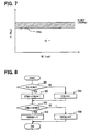
- Fig. 2 is a flowchart showing a pump and injector abnormality diagnosing method.
- the main routine shown in Fig. 2 is executed at a predetermined time interval (100 ms, for instance).
- the flowchart of the present embodiment corresponds to the control program stored in the memory.
- the flowchart shown in Fig. 2 is started when the ignition switch is switched from the off state (OFF) to the on state (ON) and the main relay is turned on to supply the ECU power from the battery to the ECU 10, and is repeatedly executed at the predetermined time interval.
- the ignition switch is switched from the on state (ON) to the off state (OFF) so that the main relay is turned off and the ECU power supply to the ECU 10 is stopped, the execution of the flowchart is compulsorily ended.
- the common rail pressure PC corresponding to the electric signal outputted from the common rail pressure sensor 35 is inputted in Step S1. Then, it is determined whether or not the common rail pressure sensor 35 is normal in Step S2. The determination of the normality of the common rail pressure sensor 35 is performed through a publicly known method of examining whether or not the electric signal (the output voltage) outputted from the common rail pressure sensor 35 is within a predetermined range (the normally used voltage range from 0.5 V to 4.5 V, for instance).
- Step S2 If the result of the determination in Step S2 is "NO”, the main routine shown in Fig. 2 is ended without executing the abnormality diagnosis of the fuel supply pump 4 and the injector 3. If the result of the determination in Step S2 is "YES”, the engine rotation speed NE sensed by the rotation speed sensor 31 is calculated in Step S3.
- a crank angle sensor is employed as the rotation speed sensor 31.
- the rotation speed sensor 31 includes a signal rotor, a multiplicity of crank angle detection teeth and an electromagnetic pickup coil.
- the signal rotor rotates in accordance with the rotation of the crankshaft 21 of the engine 1.
- the signal rotor rotates once while the crankshaft 21 rotates once, for instance.
- the multiplicity of crank angle detection teeth is formed on the outer circumference of the signal rotor.
- the electromagnetic pickup coil generates NE signal pulses in accordance with approach and separation between the electromagnetic pickup coil and the crank angle detection teeth.
- the electromagnetic pickup coil outputs a plurality of NE signal pulses while the signal rotor rotates once (or while the crankshaft 21 rotates once).
- the ECU 10 can sense the engine rotation speed NE by measuring the time intervals of the NE signal pulses.
- Step S4 pump allowance determination control shown in a graph of Fig. 3 and a subroutine of Figs. 4 to 6 is performed.
- injector allowance determination control shown in a graph of Fig. 7 and a subroutine of Fig. 8 is performed in Step S5.
- a fail-safe operation control shown in a table of Fig. 9 and a subroutine of Figs. 10 and 11 is performed in Step S6.
- the fuel supply pump 4 is designed on the premise that the fuel supply pump 4 is used in a pump usage allowable area "A" in Fig. 3.
- the common rail pressure PC may exceed a first threshold PCTH1 and may be brought into an area "B” if the common rail pressure PC is increased by some failures (for instance, an abnormality failure that the fuel discharging quantity increases and the ECU 10 cannot control the SCV 5).
- the common rail pressure PC should preferably be quickly dropped by a method of stopping the engine 1, for instance, in order to retain the reliability of the fuel supply pump 4.
- NEMAX represents a maximum value (6000 rpm, for instance) of the permissible rotation speed NE of the engine 1 for the fuel supply pump 4 and PLIMIT is the limit set pressure (the P/L opening pressure) of the common rail type fuel injection system.
- the limit set pressure PLIMIT is 250 MPa, for instance.
- the fuel supply pump 4 of the common rail type fuel injection system has a structure for ensuring lubrication of a pumping mechanism with diesel oil as the fuel. Therefore, in an area where the engine rotation speed NE is very low (as shown by an area "C” in Fig. 3) or is very high (as shown by an area “D” in Fig. 3), the influence on the reliability becomes great. In the areas "C", “D” in Fig. 3, the fuel temperature excessively rises and the injector temperature or the injector leak temperature rises to a high value. Therefore, there is a possibility that heat resistance reliability of an insulating film of a rubber seal or a solenoid coil in the injector 3 and the like may be degraded.
- the low-speed and high-pressure state is the state in which the engine rotation speed NE is equal to or lower than a predetermined value (1000 rpm, for instance) and the common rail pressure PC is high.
- the high-speed and high-pressure state is the state in which the engine rotation speed NE is equal to or higher than a predetermined value (5000 rpm, for instance) and the common rail pressure PC is high.
- a second threshold PCTH2 is set in order to indicate the area where it may be difficult to ensure the fuel lubrication.
- the pressure limiter 16 of the present embodiment mechanically opens when the fuel pressure in the common rail 2 exceeds the P/L opening pressure PLIMIT (250 Mpa, in the present embodiment as shown in Fig. 3).
- the flowchart shown in Figs. 4 to 6 is a subroutine for detecting the stay of the operating state in the area exceeding the pump usage allowable area "A" shown in Fig. 3 without erroneous diagnosis.
- the first threshold PCTH1 corresponding to the pump usage allowable area is calculated in Step S11 of the flowchart shown in Fig. 4. Then, it is determined whether or not the common rail pressure PC sensed by the common rail pressure sensor 35 is higher than the first threshold PCTH1 in Step S12. If the result of the determination in Step S12 is "YES", a counter CPMP1B is incremented in Step S13.
- Step S12 If the result of the determination in Step S12 is "NO", the counter CPMP1B is reset to zero in Step S14.
- Step S18 it is determined whether or not the previous value of the flag XCPMP1B is zero in Step S19. More specifically, it is determined whether or not XCPMP1B is incremented from zero to one in Step S19. If the result of the determination in step S19 is "YES", a counter CPMP1 is incremented by an increment masking period KCPMP1B in Step S20.
- Step S19 If the result of the determination in Step S19 is "NO", the counter CPMP1 is incremented by one in Step S21.
- the counter CPMP1B which is incremented when the common rail pressure PC exceeds the first threshold PCTH1, functions as a masking for prohibiting the increment of the counter CPMP1 and is very important for excluding the following causes of the erroneous diagnosis.
- the determination of whether or not the counter CPMP1B is greater than the increment masking period KCPMP1B is necessary in order to prohibit the increment of the counter CPMP1.
- causes of the erroneous diagnosis such as the noises instantaneously superposed on the electric signal (for instance, the pressure signal corresponding to the fuel pressure in the common rail 2) outputted from the common rail pressure sensor 35 can be excluded.
- Step S22 to Step S31 and Step S32 are basically similar to the steps from Step S11 to Step S20 and Step S21, but it is determined whether or not the common rail pressure PC exceeds the second threshold PCTH2 in the steps from Step S22 to Step S31 and Step S32.
- Step S22 the second threshold PCTH2 is calculated. Then, in Step S23, it is determined whether or not the common rail pressure PC sensed by the common rail pressure sensor 35 is higher than the second threshold PCTH2. If the result of the determination in Step S23 is "YES", a counter CPMP2B is incremented in Step S24.
- Step S23 If the result of the determination in Step S23 is "NO", the counter CPMP2B is reset to zero in Step S25.
- Step S29 If the result of the determination in Step S29 is "YES”, it is determined whether or not the previous value of the flag XCPMP2B is zero in Step S30. More specifically, it is determined whether or not the flag XCPMP2B has been incremented from zero to one in Step S30. If the result of the determination in Step S30 is "YES”, a counter CPMP2 is incremented by a value provided by multiplying an increment masking period KCPMP2B by a weight KWEIGHT in Step S31.
- Step S30 If the result of the determination in Step S30 is "NO", or if the flag XCPMP2B has not changed from zero to one but has remained one, the counter CPMP2 is incremented by the weight KWEIGHT in Step S32.
- the weight KWEIGHT takes a value (five, for instance) larger than one.
- Steps from Step S37 to Step S43 are executed in the case where the common rail pressure PC higher than the second threshold PCTH2 is sensed, in particular when the engine 1 is started.
- Step S37 it is determined whether or not the common rail pressure PC sensed by the common rail pressure sensor 35 is higher than the second threshold PCTH2. If the result of the determination in Step S37 is "YES", it is determined whether or not the engine rotation speed NE sensed by the rotation speed sensor 31 is higher than a determination value KNECPMP3 in Step S38.
- the situation of the abnormally high pressure may continue for a long time so long as the user turns the starter to start the engine 1.
- an engine stopping operation is executed in the form of control through a fail-safe operation (explained after) while the engine 1 is being cranked, the user will repeat the cranking operation until the engine actually starts.
- the situation of the abnormally high pressure will continue for a long time, so as to generate a disadvantage for the reliability of the fuel supply pump 4.
- the damage to the reliability of the fuel supply pump 4, which is caused by unnecessary repetition of the cranking operation of the engine 1, can be reduced by allowing the engine start once and by performing the engine stop operation after determining whether or not the common rail pressure PC is higher than the second threshold PCTH2.
- the operations in steps from Step S37 to Step S43 aim at providing a scheme for classifying the fail-safe operations by dividing the diagnosis flags XDGCPMP1, XDGCPMP3, which are used when the common rail pressure PC is higher than the second threshold PCTH2.
- Step S5 of the flowchart shown in Fig. 2 will be explained based on Figs. 7 and 8.
- the influence on the reliability of the injector 3 is given by the common rail pressure PC, not by the engine rotation speed NE. Therefore, the injector allowance determination threshold is set to a fixed value KINJ (MPa), as shown in Fig. 7.
- the allowance value KCINJ is set to a permissible period for continuously applying the abnormally high pressure to the injector 3.
- another effect of excluding instantaneous noises, which are superposed on the electric signal (the pressure signal corresponding to the fuel pressure in the common rail 2) outputted from the common rail pressure sensor 35, is also exerted.
- Step S6 of the flowchart shown in Fig. 2 will be explained based on Figs. 9 to 11.
- Step S6 the fail-safe operation control performed in Step S6 of the flowchart shown in Fig. 2 will be explained based on a flowchart shown in Figs. 10 and 11.
- the flowchart shown in Figs. 10 and 11 is a subroutine for realizing the demanded fail-safe level enumerated in the table shown in Fig. 9.
- an idle-up OFF flag may be set to one in Step S66.
- the value of 100 mm 3 /st is an example.
- the injection quantity limit value is set to a value greater than the maximum injection quantity of the engine 1, so that the actual injection quantity is not limited by the injection quantity limit value.
- Step S81 the final injection quantity, or the command injection quantity QFIN, is set to the minimum value between the injection quantity limit value QLIMIT and the basic injection quantity QBASE. Then, the present routine is ended.
- the basic injection quantity QBASE is calculated through a well-known method based on the engine rotation speed NE, the accelerator position ACCP and a characteristic map made in advance by measurement through experiments and the like.
- the ECU 10 calculates the energization period (the command injection period) of the injection control electromagnetic valve of the injector 3 in accordance with the common rail pressure PC and the command injection quantity QFIN, based on a characteristic map made in advance by measurement through experiments and the like.
- the ECU 10 applies the pulse-shaped injector driving current to the injection control electromagnetic valve of the injector 3 of each cylinder through the injector driving circuit EDU for the command injection period.
- the nozzle needle of the injector 3 is opened so that the fuel injection quantity corresponding to the command injection quantity QFIN is injected into the combustion chamber of each cylinder of the engine 1.
- the rotation speed of the engine 1 is controlled.
- the first threshold PCTH1 corresponds to the upper limit pressure of the pump usage allowable area, which is important for retaining the reliability of the fuel supply pump 4.
- the second threshold PCTH2 avoids the performance degradation damage (for instance, the seizing of the sliding portion due to the deterioration in the fuel lubrication) of the fuel supply pump 4.
- the injector allowance determination threshold KINJ corresponds to the upper limit pressure of the injector usage allowable area, which is important for retaining the reliability of the injector 3.
- the first threshold PCTH1, the second threshold PCTH2 and the injector allowance determination threshold KINJ are calculated based on the two-dimensional map of the common rail pressure PC and the engine rotation speed NE or the one-dimensional map of the engine rotation speed NE.
- the abnormally high-pressure state in which the common rail pressure PC exceeds the first threshold PCTH1 or the second threshold PCTH2 continues for a long time, it is determined that the abnormally high-pressure state due to the abnormality failure of the fuel supply pump 4 is formed. More specifically, the situation of the prolonged continuation of the abnormally high-pressure state in the common rail 2 where the pressure limiter 16 takes a long time to open or cannot open can be detected highly precisely.
- the emergency operation the fail-safe operation
- the engine is stopped immediately when such a situation is detected or when a predetermined period passes after the situation is detected.
- the abnormally high-pressure state in the common rail 2 can be avoided quickly and the seizing and the like of the fuel supply pump 4 can be prevented without raising the system cost.
- the reliability and the safety of the common rail type fuel injection system can be ensured.
- the abnormally high-pressure state in which the common rail pressure PC exceeds the injector allowance determination threshold KINJ, continues for a long time, it is determined that the abnormality failure of the injector 3 is generated and it is determined that the abnormally high-pressure state due to the abnormality failure is generated. More specifically, the situation of the prolonged abnormally high-pressure state in the common rail 2 where the pressure limiter 16 takes a long time to open or cannot open can be detected highly precisely.
- the injection quantity of the fuel injected into the combustion chamber of each cylinder of the engine 1 is limited to decrease the engine rotation speed to the predetermined value or under, or the injection quantity in the idling operation is increased to a predetermined value or over in order to perform the idle-up operation.
- the abnormally high-pressure state in the common rail 2 can be avoided quickly. As a result, the reliability and the safety of the common rail type fuel injection system can be ensured.
- visual displaying means such as an abnormality warning lamp (an indicator lamp) or aural displaying means such as voice and the like may be used to urge the vehicle driver to replace the fuel supply pump 4.
- an abnormality warning lamp an indicator lamp
- aural displaying means such as voice and the like
- the functional degradation the performance degradation or the reliability deterioration
- the abnormality such as the fully opening abnormality, fully closing abnormality or no injection abnormality of the injector 3 due to the breakage in the injector driving signal transmitting wire harness or due to the control abnormality of the ECU 10 are generated in the injector 3.
- visual displaying means such as an abnormality warning lamp (an indicator lamp), or aural displaying means such as voice may be used to urge the driver to replace the injector 3.
- an abnormality warning lamp an indicator lamp
- aural displaying means such as voice
- the common rail pressure sensor 35 is attached directly to the common rail 2 to detect the fuel pressure (the common rail pressure, the actual fuel pressure) in the common rail 2.
- the common rail pressure sensor 35 may be attached to the fuel pipe and the like leading from the plunger chamber (the pressurizing chamber) of the fuel supply pump 4 to the fuel passage in the injector 3 to detect the discharge pressure of the fuel discharged from the pressurizing chamber of the fuel supply pump 4, or the injection pressure of the fuel injected into the combustion chamber of each cylinder of the engine 1.
- the SCV (the drawing quantity control electromagnetic valve) 5 for changing (controlling) the drawing quantity of the fuel drawn into the plunger chamber (the pressurizing chamber) of the fuel supply pump 4 is employed.
- a discharging quantity control electromagnetic valve for changing (controlling) the discharging quantity of the fuel discharged from the plunger chamber (the pressurizing chamber) of the fuel supply pump 4 to the common rail 2 may be employed.
- the SCV 5 of the normally open type electromagnetic valve which opens fully when the energization to the electromagnetic valve is stopped, is employed.
- a normally open type discharging quantity control electromagnetic valve which opens fully when the energization to the electromagnetic valve is stopped, may be employed.
- a normally close type discharging quantity control electromagnetic valve or a normally close type drawing quantity control electromagnetic valve, which fully opens when energized may also be used.
- the command injection quantity QFIN, the command injection timing T and the target common rail pressure Pt are calculated by using the rotation speed sensor 31, the accelerator position sensor 32, the cooling water temperature sensor 33 and the fuel temperature sensor 34 as the operating condition detecting means for detecting the operating conditions of the engine 1.
- the command injection quantity QFIN, the command injection timing T and the target common rail pressure Pt may be corrected by considering the detection signals (the engine operating information) outputted from other sensors as the operating condition detecting means such as an intake temperature sensor, an intake pressure sensor, a cylinder determination sensor or an injection timing sensor.
- the ECU 10 stops the operation of the engine 1 when the state in which the common rail pressure PC is higher than the first threshold PCTH1 or the second threshold PCTH2 continues for a predetermined period.
- the ECU 10 may stop the operation of the engine 1 if a state in which the common rail pressure PC is higher than the first threshold PCTH1 and is lower than the second threshold PCTH2 continues for a predetermined period.
- the ECU 10 may stop the operation of the engine 1 if the common rail pressure PC exceeds the second threshold PCTH2.
- An engine control unit (ECU) (10) of a common rail type fuel injection system of an internal combustion engine (1) determines that an abnormality failure of a fuel supply pump (4) is generated, if an abnormally high-pressure state in which a common rail pressure exceeds a first threshold or a second threshold continues for a long time.
- the ECU (10) stops an operation of the engine (1) immediately or after an elapse of a predetermined period in accordance with a level of the abnormality failure.
- the abnormally high-pressure state in the common rail (2) can be avoided quickly and seizing and the like of the fuel supply pump (4) can be prevented.
- reliability and safety of the common rail type fuel injection system can be ensured.
Abstract
Description
Claims (13)
- A pressure accumulation type fuel injection system for accumulating high-pressure fuel, which is pressurized and pressure-fed by a fuel supply pump (4) driven by an engine (1), in a common rail (2) and for injecting the high-pressure fuel accumulated in the common rail (2) into a cylinder of the engine (1) through an injector (3), the pressure accumulation type fuel injection system including a pressure safety valve (16) that opens when the fuel pressure in the common rail (2) exceeds a limit set pressure in order to limit the fuel pressure in the common rail (2) to the limit set pressure or under, characterized by:fuel pressure sensing means (35) for sensing the fuel pressure in the common rail (2); andan engine control unit (10) for controlling the engine (1) to avoid an abnormally high-pressure state, in which the fuel pressure in the common rail (2) sensed by the fuel pressure sensing means (35) exceeds a pump usage allowable area that affects deterioration of reliability of the fuel supply pump (4) or an injector usage allowable area that affects deterioration of reliability of the injector (3), when the abnormally high-pressure state continues for a predetermined period.
- The pressure accumulation type fuel injection system as in claim 1, further characterized in thatthe engine control unit (10) includes abnormality diagnosing means (S4) for detecting an abnormality failure of the fuel supply pump (4) when an abnormally high-pressure state, in which the fuel pressure in the common rail (2) sensed by the fuel pressure sensing means (35) exceeds a first determination value corresponding to the pump usage allowable area or a second determination value that is higher than the first determination value and affects performance degradation of the fuel supply pump (4), continues for a predetermined period; andthe engine control unit (10) stops an operation of the engine (1) when a predetermined period passes after the abnormality failure of the fuel supply pump (4) is detected by the abnormality diagnosing means (S4).
- The pressure accumulation type fuel injection system as in claim 2, further characterized in thatthe engine control unit (10) includes rotation speed sensing means (S3) for sensing engine rotation speed; andthe engine control unit (10) stops the operation of the engine (1) immediately when an abnormally high-pressure state, in which the fuel pressure in the common rail (2) sensed by the fuel pressure sensing means (35) exceeds the first determination value or the second determination value and the engine rotation speed sensed by the rotation speed sensing means (S3) exceeds a determination value, continues for a predetermined period.
- The pressure accumulation type fuel injection system as in claim 2, further characterized in thatthe engine control unit (10) includes rotation speed sensing means (S3) for sensing the engine rotation speed; andthe first determination value corresponding to the pump usage allowable area and the second determination value affecting the performance degradation of the fuel supply pump (4) are calculated in accordance with the fuel pressure in the common rail (2) sensed by the fuel pressure sensing means (35) and the engine rotation speed sensed by the rotation speed sensing means (S3).
- The pressure accumulation type fuel injection system as in claim 3, further characterized in thatthe first determination value corresponding to the pump usage allowable area and the second determination value affecting the performance degradation of the fuel supply pump (4) are calculated in accordance with the fuel pressure in the common rail (2) sensed by the fuel pressure sensing means (35) and the engine rotation speed sensed by the rotation speed sensing means (S3).
- The pressure accumulation type fuel injection system as in claim 1, further characterized in thatthe engine control unit (10) includes abnormality diagnosing means (S5) for detecting an abnormality failure of the injector (3) when an abnormally high-pressure state, in which the fuel pressure in the common rail (2) sensed by the fuel pressure sensing means (35) exceeds a determination value corresponding to the injector usage allowable area, continues for a predetermined period; andthe engine control unit (10) demands limitation of an engine output of the engine (1) or an idle-up operation for increasing idling rotation speed of the engine (1) when the abnormality failure of the injector (3) is detected by the abnormality diagnosing means (S5).
- The pressure accumulation type fuel injection system as in claim 6, further characterized in thatthe engine control unit (10) includes rotation speed sensing means (S3) for sensing engine rotation speed; andthe determination value corresponding to the injector usage allowable area is calculated in accordance with the engine rotation speed sensed by the rotation speed sensing means (S3).
- The pressure accumulation type fuel injection system as in claim 1, further characterized in thatthe engine control unit (10) includes abnormality diagnosing means (S4, S5) for detecting an abnormality failure of the fuel supply pump (4) or the injector (3) and visual or aural displaying means for urging replacement of the fuel supply pump (4) or the injector (3) when the abnormality failure of the fuel supply pump (4) or the injector (3) is detected by the abnormality diagnosing means (S4, S5).
- The pressure accumulation type fuel injection system as in claim 1, further characterized in thatthe engine control unit (10) includes first abnormality diagnosing means (S2) for detecting an abnormality failure of the fuel pressure sensing means (35) and second abnormality diagnosing means (S4, S5) for detecting an abnormality failure of the fuel supply pump (4) or the injector (3), andthe engine control unit (10) prohibits the detection of the abnormality failure of the fuel supply pump (4) or the injector (3) with the second abnormality diagnosing means (S4, S5) if the abnormality failure of the fuel pressure sensing means (35) is detected by the first abnormality diagnosing means (S2).
- The pressure accumulation type fuel injection system as in claim 1, further characterized in thatthe fuel supply pump (4) includes a pressurizing chamber for pressurizing the fuel drawn through a fuel suction passage and includes a suction control valve (5) for regulating the fuel pressure in the common rail (2) by changing a discharging quantity of the fuel discharged from the pressurizing chamber into the common rail (2) in accordance with an opening area of the fuel suction passage or a lifting degree of a valve member; andthe suction control valve (5) is a normally open type electromagnetic valve, which opens fully when energization thereto is stopped.
- The pressure accumulation type fuel injection system as in claim 2, further characterized in thatthe engine control unit (10) sets a first weight added to a first elapsed time of a state in which the fuel pressure in the common rail (2) continuously exceeds the first determination value and a second weight added to a second elapsed time of a state in which the fuel pressure in the common rail (2) continuously exceeds the second determination value so that the second weight is greater than the first weight, andthe engine control unit (10) stops the operation of the engine (1) when the sum of the first elapsed time and the first weight or the sum of the second elapsed time and the second weight exceeds a predetermined value.
- The pressure accumulation type fuel injection system as in claim 2, further characterized in thatthe engine control unit (10) stops the operation of the engine (1) when a state in which the fuel pressure in the common rail (2) is higher than the first determination valve and is lower than the second determination value continues for a predetermined period.
- The pressure accumulation type fuel injection system as in claim 2, further characterized in thatthe engine control unit (10) stops the operation of the engine (1) when the fuel pressure in the common rail (2) exceeds the second determination value.
Priority Applications (1)
| Application Number | Priority Date | Filing Date | Title |
|---|---|---|---|
| EP14164422.9A EP2799700B1 (en) | 2003-01-27 | 2004-01-26 | Pressure accumulation type fuel injection system |
Applications Claiming Priority (2)
| Application Number | Priority Date | Filing Date | Title |
|---|---|---|---|
| JP2003017787 | 2003-01-27 | ||
| JP2003017787A JP3972823B2 (en) | 2003-01-27 | 2003-01-27 | Accumulated fuel injection system |
Related Child Applications (2)
| Application Number | Title | Priority Date | Filing Date |
|---|---|---|---|
| EP14164422.9A Division-Into EP2799700B1 (en) | 2003-01-27 | 2004-01-26 | Pressure accumulation type fuel injection system |
| EP14164422.9A Division EP2799700B1 (en) | 2003-01-27 | 2004-01-26 | Pressure accumulation type fuel injection system |
Publications (3)
| Publication Number | Publication Date |
|---|---|
| EP1441120A2 true EP1441120A2 (en) | 2004-07-28 |
| EP1441120A3 EP1441120A3 (en) | 2011-04-13 |
| EP1441120B1 EP1441120B1 (en) | 2015-09-09 |
Family
ID=32588714
Family Applications (2)
| Application Number | Title | Priority Date | Filing Date |
|---|---|---|---|
| EP04001588.5A Expired - Fee Related EP1441120B1 (en) | 2003-01-27 | 2004-01-26 | Pressure accumulation type fuel injection system |
| EP14164422.9A Expired - Fee Related EP2799700B1 (en) | 2003-01-27 | 2004-01-26 | Pressure accumulation type fuel injection system |
Family Applications After (1)
| Application Number | Title | Priority Date | Filing Date |
|---|---|---|---|
| EP14164422.9A Expired - Fee Related EP2799700B1 (en) | 2003-01-27 | 2004-01-26 | Pressure accumulation type fuel injection system |
Country Status (2)
| Country | Link |
|---|---|
| EP (2) | EP1441120B1 (en) |
| JP (1) | JP3972823B2 (en) |
Cited By (9)
| Publication number | Priority date | Publication date | Assignee | Title |
|---|---|---|---|---|
| WO2006015893A1 (en) * | 2004-08-05 | 2006-02-16 | Robert Bosch Gmbh | Test method |
| WO2007097226A1 (en) * | 2006-02-21 | 2007-08-30 | Aisan Kogyo Kabushiki Kaisha | Fault diagnosis system in load driving arrangement and fuel pump control system |
| EP2151565A1 (en) * | 2007-04-26 | 2010-02-10 | Bosch Corporation | Injector protection control method, and common rail fuel injection control device |
| DE102009050469A1 (en) * | 2009-10-23 | 2011-04-28 | Mtu Friedrichshafen Gmbh | Method for controlling and regulating an internal combustion engine |
| US8881707B2 (en) | 2010-10-18 | 2014-11-11 | Denso Corporation | Fail-safe controller for direct injection engine |
| US9657653B2 (en) | 2014-06-09 | 2017-05-23 | Caterpillar Inc. | Gas pressure high and low detection |
| CN109488473A (en) * | 2018-12-17 | 2019-03-19 | 中国船舶重工集团公司第七研究所 | The online anticipation system of engine and online pre-judging method |
| WO2019057666A1 (en) * | 2017-09-25 | 2019-03-28 | Mtu Friedrichshafen Gmbh | Method for operating an internal combustion engine having an injection system, and injection system for carrying out such a method |
| CN115126637A (en) * | 2022-07-20 | 2022-09-30 | 潍柴动力股份有限公司 | Injection pump detection device, high-pressure common rail fuel system and automobile |
Families Citing this family (11)
| Publication number | Priority date | Publication date | Assignee | Title |
|---|---|---|---|---|
| JP4492508B2 (en) * | 2005-09-29 | 2010-06-30 | 株式会社デンソー | Fuel injection control device |
| JP2007327404A (en) * | 2006-06-07 | 2007-12-20 | Denso Corp | Common rail type fuel injection device |
| JP4573218B2 (en) * | 2006-06-09 | 2010-11-04 | 株式会社デンソー | Fuel injection device |
| JP4922906B2 (en) * | 2007-12-10 | 2012-04-25 | 日立オートモティブシステムズ株式会社 | High pressure fuel supply device and control device for internal combustion engine |
| JP4909973B2 (en) | 2008-11-14 | 2012-04-04 | 日立オートモティブシステムズ株式会社 | Control device for internal combustion engine |
| JP5798796B2 (en) * | 2011-05-25 | 2015-10-21 | 日立オートモティブシステムズ株式会社 | Engine control device |
| JP5718841B2 (en) * | 2012-03-12 | 2015-05-13 | トヨタ自動車株式会社 | Control device for internal combustion engine |
| JP5861601B2 (en) * | 2012-09-05 | 2016-02-16 | 株式会社デンソー | Injector drive device |
| KR20160111939A (en) * | 2014-01-27 | 2016-09-27 | 바르질라 스위츠랜드 리미티드 | Injection controller and method for detection of injection equipment failure in a diesel engine |
| JP6951260B2 (en) * | 2018-01-11 | 2021-10-20 | 本田技研工業株式会社 | Fuel injection control device |
| DK180386B1 (en) * | 2019-06-14 | 2021-02-24 | Man Energy Solutions Filial Af Man Energy Solutions Se Tyskland | Internal combustion engine |
Citations (1)
| Publication number | Priority date | Publication date | Assignee | Title |
|---|---|---|---|---|
| JP2001295685A (en) | 2000-04-17 | 2001-10-26 | Denso Corp | Accumulator fuel injector |
Family Cites Families (9)
| Publication number | Priority date | Publication date | Assignee | Title |
|---|---|---|---|---|
| JP3460319B2 (en) * | 1994-08-19 | 2003-10-27 | いすゞ自動車株式会社 | Pressure accumulating fuel injection device and control method thereof |
| JPH08338335A (en) * | 1995-06-09 | 1996-12-24 | Nippondenso Co Ltd | Fuel feeding device for internal combustion engine |
| JPH09119335A (en) * | 1995-10-27 | 1997-05-06 | Isuzu Motors Ltd | Fuel supplying controller of engine |
| DE19604552B4 (en) * | 1996-02-08 | 2007-10-31 | Robert Bosch Gmbh | Method and device for controlling an internal combustion engine |
| DE19626689C1 (en) * | 1996-07-03 | 1997-11-20 | Bosch Gmbh Robert | Common-rail fuel injection system monitoring method |
| JP3814916B2 (en) * | 1997-02-26 | 2006-08-30 | トヨタ自動車株式会社 | Fuel injection device for internal combustion engine |
| JP2000303886A (en) * | 1999-04-20 | 2000-10-31 | Denso Corp | Abnormality detecting device for high-pressure fuel system |
| JP2002070632A (en) * | 2000-08-25 | 2002-03-08 | Hitachi Ltd | Engine controller with failure diagnostic device |
| JP2003184616A (en) * | 2001-12-17 | 2003-07-03 | Nissan Motor Co Ltd | Fail safe control device for fuel injection system |
-
2003
- 2003-01-27 JP JP2003017787A patent/JP3972823B2/en not_active Expired - Fee Related
-
2004
- 2004-01-26 EP EP04001588.5A patent/EP1441120B1/en not_active Expired - Fee Related
- 2004-01-26 EP EP14164422.9A patent/EP2799700B1/en not_active Expired - Fee Related
Patent Citations (1)
| Publication number | Priority date | Publication date | Assignee | Title |
|---|---|---|---|---|
| JP2001295685A (en) | 2000-04-17 | 2001-10-26 | Denso Corp | Accumulator fuel injector |
Cited By (15)
| Publication number | Priority date | Publication date | Assignee | Title |
|---|---|---|---|---|
| US7775102B2 (en) | 2004-08-05 | 2010-08-17 | Robert Bosch Gmbh | Method for testing a high-pressure pump in a fuel system |
| WO2006015893A1 (en) * | 2004-08-05 | 2006-02-16 | Robert Bosch Gmbh | Test method |
| US8195355B2 (en) | 2006-02-21 | 2012-06-05 | Aisan Kogyo Kabushiki Kaisha | Fault diagnosis system in load driving arrangement and fuel pump control system |
| WO2007097226A1 (en) * | 2006-02-21 | 2007-08-30 | Aisan Kogyo Kabushiki Kaisha | Fault diagnosis system in load driving arrangement and fuel pump control system |
| EP2151565A1 (en) * | 2007-04-26 | 2010-02-10 | Bosch Corporation | Injector protection control method, and common rail fuel injection control device |
| EP2151565A4 (en) * | 2007-04-26 | 2011-11-30 | Bosch Corp | Injector protection control method, and common rail fuel injection control device |
| DE102009050469A1 (en) * | 2009-10-23 | 2011-04-28 | Mtu Friedrichshafen Gmbh | Method for controlling and regulating an internal combustion engine |
| DE102009050469B4 (en) * | 2009-10-23 | 2015-11-05 | Mtu Friedrichshafen Gmbh | Method for controlling and regulating an internal combustion engine |
| US8881707B2 (en) | 2010-10-18 | 2014-11-11 | Denso Corporation | Fail-safe controller for direct injection engine |
| US9657653B2 (en) | 2014-06-09 | 2017-05-23 | Caterpillar Inc. | Gas pressure high and low detection |
| WO2019057666A1 (en) * | 2017-09-25 | 2019-03-28 | Mtu Friedrichshafen Gmbh | Method for operating an internal combustion engine having an injection system, and injection system for carrying out such a method |
| CN109488473A (en) * | 2018-12-17 | 2019-03-19 | 中国船舶重工集团公司第七研究所 | The online anticipation system of engine and online pre-judging method |
| CN109488473B (en) * | 2018-12-17 | 2021-08-13 | 中国船舶重工集团公司第七一一研究所 | Online prejudgment system and online prejudgment method of engine |
| CN115126637A (en) * | 2022-07-20 | 2022-09-30 | 潍柴动力股份有限公司 | Injection pump detection device, high-pressure common rail fuel system and automobile |
| CN115126637B (en) * | 2022-07-20 | 2024-02-20 | 潍柴动力股份有限公司 | High-pressure common rail fuel system and automobile |
Also Published As
| Publication number | Publication date |
|---|---|
| EP1441120A3 (en) | 2011-04-13 |
| JP3972823B2 (en) | 2007-09-05 |
| EP1441120B1 (en) | 2015-09-09 |
| EP2799700A1 (en) | 2014-11-05 |
| EP2799700B1 (en) | 2015-07-22 |
| JP2004225673A (en) | 2004-08-12 |
Similar Documents
| Publication | Publication Date | Title |
|---|---|---|
| EP2799700B1 (en) | Pressure accumulation type fuel injection system | |
| US7933712B2 (en) | Defective injection detection device and fuel injection system having the same | |
| US6871633B1 (en) | Abnormality diagnosis apparatus for high pressure fuel system of cylinder injection type internal combustion engine | |
| US6715468B2 (en) | Fuel injection system | |
| JP3796912B2 (en) | Fuel injection device for internal combustion engine | |
| EP0860600B1 (en) | A fuel injection system for an internal combustion engine | |
| US7373918B2 (en) | Diesel engine control system | |
| JP4591390B2 (en) | Pump fault diagnosis device | |
| JP4659648B2 (en) | Abnormality judgment device for fuel supply system | |
| US6539921B1 (en) | Fuel injection system with fuel pressure sensor | |
| US6964262B2 (en) | Accumulator fuel injection system capable of preventing abnormally high pressure | |
| JP2011185158A (en) | Failure diagnostic device of high pressure fuel supply system of internal combustion engine | |
| JP2005171931A (en) | Fuel injection control device | |
| JP2013253560A (en) | Fuel supply device | |
| JP3941667B2 (en) | Accumulated fuel injection system | |
| JP3876694B2 (en) | Common rail fuel injection system | |
| JP2005155561A (en) | Fuel injection device for internal combustion engine | |
| JP2004225630A (en) | Accumulator fuel injection system | |
| JP5287673B2 (en) | Abnormal site diagnosis device | |
| JP4300582B2 (en) | Fuel supply device | |
| JP2005344573A (en) | Fuel injection device for internal combustion engine | |
| JP5556572B2 (en) | Fuel pressure sensor diagnostic device | |
| JP2004324416A (en) | Troubleshooting device for internal combustion engine | |
| JP2003293835A (en) | Accumulator fuel injection system | |
| JP2003161196A (en) | Accumulator fuel injection unit |
Legal Events
| Date | Code | Title | Description |
|---|---|---|---|
| PUAI | Public reference made under article 153(3) epc to a published international application that has entered the european phase |
Free format text: ORIGINAL CODE: 0009012 |
|
| AK | Designated contracting states |
Kind code of ref document: A2 Designated state(s): AT BE BG CH CY CZ DE DK EE ES FI FR GB GR HU IE IT LI LU MC NL PT RO SE SI SK TR |
|
| AX | Request for extension of the european patent |
Extension state: AL LT LV MK |
|
| PUAL | Search report despatched |
Free format text: ORIGINAL CODE: 0009013 |
|
| AK | Designated contracting states |
Kind code of ref document: A3 Designated state(s): AT BE BG CH CY CZ DE DK EE ES FI FR GB GR HU IE IT LI LU MC NL PT RO SE SI SK TR |
|
| AX | Request for extension of the european patent |
Extension state: AL LT LV MK |
|
| 17P | Request for examination filed |
Effective date: 20110429 |
|
| 17Q | First examination report despatched |
Effective date: 20110614 |
|
| AKX | Designation fees paid |
Designated state(s): DE FR GB |
|
| GRAP | Despatch of communication of intention to grant a patent |
Free format text: ORIGINAL CODE: EPIDOSNIGR1 |
|
| INTG | Intention to grant announced |
Effective date: 20150330 |
|
| RIN1 | Information on inventor provided before grant (corrected) |
Inventor name: UCHIYAMA, KEN |
|
| GRAS | Grant fee paid |
Free format text: ORIGINAL CODE: EPIDOSNIGR3 |
|
| GRAA | (expected) grant |
Free format text: ORIGINAL CODE: 0009210 |
|
| AK | Designated contracting states |
Kind code of ref document: B1 Designated state(s): DE FR GB |
|
| REG | Reference to a national code |
Ref country code: GB Ref legal event code: FG4D |
|
| REG | Reference to a national code |
Ref country code: DE Ref legal event code: R096 Ref document number: 602004047845 Country of ref document: DE |
|
| REG | Reference to a national code |
Ref country code: FR Ref legal event code: PLFP Year of fee payment: 13 |
|
| REG | Reference to a national code |
Ref country code: DE Ref legal event code: R084 Ref document number: 602004047845 Country of ref document: DE |
|
| PGFP | Annual fee paid to national office [announced via postgrant information from national office to epo] |
Ref country code: FR Payment date: 20160121 Year of fee payment: 13 Ref country code: GB Payment date: 20160120 Year of fee payment: 13 |
|
| REG | Reference to a national code |
Ref country code: DE Ref legal event code: R097 Ref document number: 602004047845 Country of ref document: DE |
|
| PLBE | No opposition filed within time limit |
Free format text: ORIGINAL CODE: 0009261 |
|
| STAA | Information on the status of an ep patent application or granted ep patent |
Free format text: STATUS: NO OPPOSITION FILED WITHIN TIME LIMIT |
|
| 26N | No opposition filed |
Effective date: 20160610 |
|
| GBPC | Gb: european patent ceased through non-payment of renewal fee |
Effective date: 20170126 |
|
| REG | Reference to a national code |
Ref country code: FR Ref legal event code: ST Effective date: 20170929 |
|
| PG25 | Lapsed in a contracting state [announced via postgrant information from national office to epo] |
Ref country code: FR Free format text: LAPSE BECAUSE OF NON-PAYMENT OF DUE FEES Effective date: 20170131 |
|
| PG25 | Lapsed in a contracting state [announced via postgrant information from national office to epo] |
Ref country code: GB Free format text: LAPSE BECAUSE OF NON-PAYMENT OF DUE FEES Effective date: 20170126 |
|
| PGFP | Annual fee paid to national office [announced via postgrant information from national office to epo] |
Ref country code: DE Payment date: 20220119 Year of fee payment: 19 |
|
| REG | Reference to a national code |
Ref country code: DE Ref legal event code: R119 Ref document number: 602004047845 Country of ref document: DE |
|
| PG25 | Lapsed in a contracting state [announced via postgrant information from national office to epo] |
Ref country code: DE Free format text: LAPSE BECAUSE OF NON-PAYMENT OF DUE FEES Effective date: 20230801 |