EP1441114B1 - Internal combustion engine for motorcycle - Google Patents
Internal combustion engine for motorcycle Download PDFInfo
- Publication number
- EP1441114B1 EP1441114B1 EP02760832.2A EP02760832A EP1441114B1 EP 1441114 B1 EP1441114 B1 EP 1441114B1 EP 02760832 A EP02760832 A EP 02760832A EP 1441114 B1 EP1441114 B1 EP 1441114B1
- Authority
- EP
- European Patent Office
- Prior art keywords
- cylinder
- internal combustion
- combustion engine
- cooling fins
- motorcycle
- Prior art date
- Legal status (The legal status is an assumption and is not a legal conclusion. Google has not performed a legal analysis and makes no representation as to the accuracy of the status listed.)
- Expired - Lifetime
Links
Images



Classifications
-
- F—MECHANICAL ENGINEERING; LIGHTING; HEATING; WEAPONS; BLASTING
- F01—MACHINES OR ENGINES IN GENERAL; ENGINE PLANTS IN GENERAL; STEAM ENGINES
- F01P—COOLING OF MACHINES OR ENGINES IN GENERAL; COOLING OF INTERNAL-COMBUSTION ENGINES
- F01P1/00—Air cooling
- F01P1/02—Arrangements for cooling cylinders or cylinder heads, e.g. ducting cooling-air from its pressure source to cylinders or along cylinders
-
- F—MECHANICAL ENGINEERING; LIGHTING; HEATING; WEAPONS; BLASTING
- F02—COMBUSTION ENGINES; HOT-GAS OR COMBUSTION-PRODUCT ENGINE PLANTS
- F02B—INTERNAL-COMBUSTION PISTON ENGINES; COMBUSTION ENGINES IN GENERAL
- F02B61/00—Adaptations of engines for driving vehicles or for driving propellers; Combinations of engines with gearing
- F02B61/02—Adaptations of engines for driving vehicles or for driving propellers; Combinations of engines with gearing for driving cycles
-
- F—MECHANICAL ENGINEERING; LIGHTING; HEATING; WEAPONS; BLASTING
- F02—COMBUSTION ENGINES; HOT-GAS OR COMBUSTION-PRODUCT ENGINE PLANTS
- F02B—INTERNAL-COMBUSTION PISTON ENGINES; COMBUSTION ENGINES IN GENERAL
- F02B75/00—Other engines
- F02B75/16—Engines characterised by number of cylinders, e.g. single-cylinder engines
-
- F—MECHANICAL ENGINEERING; LIGHTING; HEATING; WEAPONS; BLASTING
- F01—MACHINES OR ENGINES IN GENERAL; ENGINE PLANTS IN GENERAL; STEAM ENGINES
- F01P—COOLING OF MACHINES OR ENGINES IN GENERAL; COOLING OF INTERNAL-COMBUSTION ENGINES
- F01P2050/00—Applications
- F01P2050/16—Motor-cycles
Definitions
- the present invention relates to an internal combustion engine provided with cooling fins for a motorcycle.
- an internal combustion engine 01 for a small motorcycle is suspended from a front frame 02 extending obliquely downward toward the rear from an upper part of a front fork with the axis C of its cylinder substantially horizontally extended.
- the internal combustion engine 01 comprises, as principal parts, a crankcase 04, a cylinder 05 and a cylinder head 06.
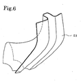
- the opposite sides of the cylinder 05 and the cylinder head 06 are covered with a leg shield 03 of a shape shown in Fig. 6 and having right and left side walls substantially vertically extending on the opposite sides, respectively, of the front frame 02.
- a space defined by the internal combustion engine 01, the front frame 03, and the leg shield 03 having the right and the left side wall extending on the opposite sides of the internal combustion engine 01 and the front frame 02 is tapered forward.
- Various devices 07 are installed in a rear end region between the crankcase 04 and the front frame 02 of the tapered space.
- cooling fins 05f formed on the upper, lower, right and left side surfaces of the cylinder 05, and cooling fins 06f formed on the upper, lower, right and left side surfaces of the cylinder head 06 are extended parallel to the axis C of the cylinder 05, so that wind W is able to flow in a direction parallel to the axis C through spaces between the cooling fins 05f and 06f to cool the internal combustion engine 01 effectively.
- JP 62 223444 A disclosed a motorcycle according to the preamble part of claim 1.
- This motorcycle comprises a 2-cycle engine having a substantially cylindrically engine body.
- the engine includes a cylinder head and a cylinder, the axis of the cylinder extending substantially horizontally.
- the engine is provided with a first type of cooling fins on the upper and lower sides of the cylinder head and also partly on the lower side of the cylinder, the first type of cooling fins extending in a horizontal and vertical direction.
- the engine is further provided with a second type of cooling fins on the left and right sides of the cylinder head and of the cylinder, the second type of cooling fins extending diagonal from the upper front to the lower back of the engine.
- It is an object of the present invention to provide a motorcycle comprising an internal combustion engine provided with cooling fins capable of effectively cooling the internal combustion engine when a space sufficient for wind to flow through easily cannot be secured in the depth of a space defined by the internal combustion engine, a front frame and side wall substantially vertically extending on the right and the left side of the front frame.
- the present invention provides a motorcycle comprising an internal combustion engine according to claim 1.
- wind that impinges against the top of the cylinder head of the internal combustion engine disposed between the right and the left side wall of the leg shield is divided roughly into an upper air stream and a lower air stream, and the upper and the lower air stream flow through spaces between the first cooling fins parallel to the axis of the cylinder and formed on the upper and the lower side surfaces of the cylinder head and the cylinder.
- the internal combustion engine of the present invention for a motorcycle is provided with cooling fins extending in the flowing directions of air streams depending on the arrangement of the devices of the internal combustion engine, the internal combustion engine can be effectively cooled, the temperature of the lubricating oil can be lowered and the durability of the internal combustion engine can be enhanced.
- a principal part of a body frame is formed by connecting a curved rear frame 3 extending obliquely upward toward the rear to the rear end of a front frame 2 extending obliquely downward toward the rear from an upper part of a front fork 5.
- a head pipe 4 connected to the front part of the front frame 2 supports an upper part of the front fork 5 for turning.
- a front wheel is supported for rotation on the lower end of the front fork 5.
- a handlebar 7 is attached to the upper end of the front fork 5.
- An internal combustion engine 8 includes a crankcase 9, a cylinder 10 and a cylinder head 11.
- the internal combustion engine 8 is suspended from the front frame 2 with the axis C of the cylinder 10 substantially horizontally extended.
- a chain case 12 is extended rearward from the crankcase 9, and a rear wheel 13 is supported for rotation on a rear end part of the chain case 12.
- a cushioning device 14 has an upper end connected to a rear part of the rear frame 3 and a lower end connected to a rear part of the chain case 12.
- a leg shield 15 straddling the front frame 2 has right and left side walls covering the cylinder 10 and the cylinder head 11 of the internal combustion engine 8.
- the rear frame 3 is covered with a rear cover 16, and a seat 17 is disposed on top of the rear cover 16.
- the internal combustion engine 8 is disposed under the front frame 2 with the axis C of the cylinder 10 substantially horizontally extended.
- the motorcycle 1 is supposed to run forward to the right as viewed in Fig. 2 .
- the internal combustion engine 8 includes as principal components, in addition to the crankcase 9, the cylinder 10 and the cylinder head 11, various devices 18 disposed above the crankcase 9.
- the cylinder 10 and the cylinder head 11, which are heated at high temperatures, are provided on their outer surfaces with cooling fins,
- first cooling fins 11a parallel to the axis C of the cylinder 10 are formed on the upper and the lower side surface of the cylinder head 11
- second cooling fins 11b perpendicular or substantially perpendicular to the axis C of the cylinder 10 are formed on the right and the left side surface of the cylinder head 11.
- the first and the second cooling fins are continuous and straight.
- Fig. 3 is a perspective view of the cylinder 10.
- the axis C of the cylinder 10 is indicated by a chain line.
- the arrows U, D, R and L indicate an upward direction, a downward direction, a rightward direction and a leftward direction, respectively, when the internal combustion engine 8 including the cylinder 10 is mounted on the motorcycle.
- the upper, the lower, the right and the left side surface of the cylinder 10 correspond to the directions indicated by the arrows U, D. R and L, respectively.
- the axis C of the cylinder 10 coincides with the center axis of a cylinder bore 10c formed in the cylinder 10.
- a chain chamber 10d for a timing chain is formed beside the cylinder bore 10c.
- the cylinder 10 is provided with a tensioner lifter mounting hole 10e so as to extend between the upper side surface of the cylinder 10 and the chain chamber 10d.
- a tensioner lifter takes up a slack in the timing chain.
- Bolt holes 10f are formed in peripheral parts of the cylinder 10. Connecting bolts are passed through the bolt holes 10f to fasten together the crankcase 9, the cylinder 10 and the cylinder head 11.
- the first cooling fins 10a parallel to the axis C are formed on the upper and the lower side surface of the cylinder 10, and the second cooling fins 10b perpendicular or substantially perpendicular to the axis C are formed on the right and the left side surface of the cylinder 10.
- the cooling fins 10a and 10b are formed integrally with the cylinder 10 when the cylinder 10 is formed by casting an aluminum material.
- the cooling fins 11a and 11b of the cylinder head 11 are formed integrally with the cylinder head 11 when the cylinder head 11 is formed by casting an aluminum material.
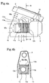
- Figs. 4a and 4b are views of assistance in explaining the function of the present invention.
- Fig. 4a is a side elevation of the internal combustion engine 8
- Fig. 4b is a sectional view taken on line B-B in Fig. 4a .
- the internal combustion engine 8 is suspended from the front frame 2.
- Principal components of the internal combustion engine 8 shown in Figs. 4a and 4b are the crankcase 9, the cylinder 10, the cylinder head 11, and the devices 18 disposed between the front frame 2 and the crankcase 9.
- the leg shield 15 extends downward on the right and the left side of the internal combustion engine 8 to protect the rider's legs from high-temperature heat.
- the left side wall of the leg shield 15 is removed.
- a space defined by the front frame 2, the leg shield 15 and the crankcase 9 is occupied by the devices 18, and gaps for air to flow are scarcely available in the space.
- Wind Wa that impinges against the top of the cylinder head 11 is divided roughly into an upper air stream and a lower air stream, and the upper and the lower air stream flow through spaces between the first cooling fins 11a and 10a parallel to the axis C and formed on the upper and the lower side surfaces of the cylinder 10 and the cylinder head 11.
- Wind Wb that flows into the space between the front frame 2 and the cylinder head 11 is unable to flow rearward because the depth of the space is substantially blocked.
- the wind Wb is divided into right and left air streams, and the right and the left air stream flow downward through spaces between the second cooling fins 11b and 10b perpendicular to the axis C and formed on the right and the left side surface of the cylinder head 11 and the cylinder 10.
- the air streams flowed through the spaces between the first cooling fins 11a and 10a parallel to the axis C of the cylinder flow downward along the right and the left side surface of the cylinder 10.
- the second cooling fins 11b and 10b are formed straight, but they may be formed partly in a curved shape to ensure smooth flow of the air therealong.
Landscapes
- Engineering & Computer Science (AREA)
- Chemical & Material Sciences (AREA)
- Combustion & Propulsion (AREA)
- Mechanical Engineering (AREA)
- General Engineering & Computer Science (AREA)
- Cylinder Crankcases Of Internal Combustion Engines (AREA)
Description
- The present invention relates to an internal combustion engine provided with cooling fins for a motorcycle.
- Referring to
Fig. 5 , aninternal combustion engine 01 for a small motorcycle is suspended from afront frame 02 extending obliquely downward toward the rear from an upper part of a front fork with the axis C of its cylinder substantially horizontally extended. Theinternal combustion engine 01 comprises, as principal parts, acrankcase 04, acylinder 05 and acylinder head 06. The opposite sides of thecylinder 05 and thecylinder head 06 are covered with aleg shield 03 of a shape shown inFig. 6 and having right and left side walls substantially vertically extending on the opposite sides, respectively, of thefront frame 02. - In this small motorcycle, a space defined by the
internal combustion engine 01, thefront frame 03, and theleg shield 03 having the right and the left side wall extending on the opposite sides of theinternal combustion engine 01 and thefront frame 02 is tapered forward.Various devices 07 are installed in a rear end region between thecrankcase 04 and thefront frame 02 of the tapered space. If a sufficient space for wind to flow through can be secured in the rear region of the tapered space, coolingfins 05f formed on the upper, lower, right and left side surfaces of thecylinder 05, and coolingfins 06f formed on the upper, lower, right and left side surfaces of thecylinder head 06 are extended parallel to the axis C of thecylinder 05, so that wind W is able to flow in a direction parallel to the axis C through spaces between the cooling fins 05f and 06f to cool theinternal combustion engine 01 effectively. - Even if the
crankcase 04 is enlarged, thedevices 07 installed in the space between thecrankcase 04 and thefront frame 02 are enlarged and the number of devices is increased as theinternal combustion engine 01 is enlarged, the width of the space between the right and the left side wall of theleg shield 03 cannot be increased because the distance between the right and the left side wall of theleg shield 03 cannot be increased because of restrictions relating to controllability. Consequently, in some cases, a space sufficient for wind to flow through cannot be secured in the depth of the space defined by thefront frame 02, and the right and the left side wall of theleg shield 03. If wind is unable to flow through the space, incoming wind is unable to flow rearward through the space, and flows downward along the right and the left side of thecylinder 05 and thecylinder head 06. - When the
cylinder 05 and thecylinder head 06 are provided on their right and left side walls with thecooling fins cylinder 05 as shown inFig. 5 , and wind flows downward, the cooling fins 05f and 06f obstruct the flow of wind and, consequently, the effect of wind in cooling the internal combustion engine is reduced. Furthermore,JP 62 223444 A claim 1. This motorcycle comprises a 2-cycle engine having a substantially cylindrically engine body. The engine includes a cylinder head and a cylinder, the axis of the cylinder extending substantially horizontally. The engine is provided with a first type of cooling fins on the upper and lower sides of the cylinder head and also partly on the lower side of the cylinder, the first type of cooling fins extending in a horizontal and vertical direction. The engine is further provided with a second type of cooling fins on the left and right sides of the cylinder head and of the cylinder, the second type of cooling fins extending diagonal from the upper front to the lower back of the engine. - It is an object of the present invention to provide a motorcycle comprising an internal combustion engine provided with cooling fins capable of effectively cooling the internal combustion engine when a space sufficient for wind to flow through easily cannot be secured in the depth of a space defined by the internal combustion engine, a front frame and side wall substantially vertically extending on the right and the left side of the front frame.
- To achieve the object, the present invention provides a motorcycle comprising an internal combustion engine according to
claim 1. - When the motorcycle provided with the internal combustion engine runs, wind that impinges against the top of the cylinder head of the internal combustion engine disposed between the right and the left side wall of the leg shield is divided roughly into an upper air stream and a lower air stream, and the upper and the lower air stream flow through spaces between the first cooling fins parallel to the axis of the cylinder and formed on the upper and the lower side surfaces of the cylinder head and the cylinder. When the depth of the space defined by the internal combustion engine, the front frame, and the right and the left side wall of the leg shield is blocked and there is no space sufficient for wind to flow easily through, wind that flows into the space is unable to flow rearward and is divided into right and left air streams, and the right and the left air stream flow downward through the spaces between the second cooling fins perpendicular to the axis of the cylinder and formed on the right and the left side surfaces of the cylinder head and the cylinder.
- Since the internal combustion engine of the present invention for a motorcycle is provided with cooling fins extending in the flowing directions of air streams depending on the arrangement of the devices of the internal combustion engine, the internal combustion engine can be effectively cooled, the temperature of the lubricating oil can be lowered and the durability of the internal combustion engine can be enhanced.
-
-
Fig. 1 is a side elevation of a small motorcycle provided with an internal combustion engine in a preferred embodiment according to the present invention; -
Fig. 2 is a perspective view of the internal combustion engine in the preferred embodiment; -
Fig. 3 is a perspective view of a cylinder included in the internal combustion engine; -
Fig. 4a is a side elevation of the internal combustion engine shown inFig. 2 of assistance in explaining the function of the embodiment; -
Fig. 4b is a sectional view taken on line B-B inFig. 4a ; -
Fig. 5 is a perspective view of a conventional internal combustion engine for a small motorcycle; and -
Fig. 6 is a perspective view of a leg shield employed in the motorcycle ofFig. 5 . - Referring to
Fig. 1 showing asmall motorcycle 1 provided with an internal combustion engine in a preferred embodiment according to the present invention in a side elevation, a principal part of a body frame is formed by connecting a curvedrear frame 3 extending obliquely upward toward the rear to the rear end of afront frame 2 extending obliquely downward toward the rear from an upper part of a front fork 5. Ahead pipe 4 connected to the front part of thefront frame 2 supports an upper part of the front fork 5 for turning. A front wheel is supported for rotation on the lower end of the front fork 5. A handlebar 7 is attached to the upper end of the front fork 5. - An
internal combustion engine 8 includes acrankcase 9, acylinder 10 and acylinder head 11. Theinternal combustion engine 8 is suspended from thefront frame 2 with the axis C of thecylinder 10 substantially horizontally extended. Achain case 12 is extended rearward from thecrankcase 9, and arear wheel 13 is supported for rotation on a rear end part of thechain case 12. Acushioning device 14 has an upper end connected to a rear part of therear frame 3 and a lower end connected to a rear part of thechain case 12. Aleg shield 15 straddling thefront frame 2 has right and left side walls covering thecylinder 10 and thecylinder head 11 of theinternal combustion engine 8. Therear frame 3 is covered with arear cover 16, and aseat 17 is disposed on top of therear cover 16. - Referring to
Fig. 2 showing theinternal combustion engine 8 in a perspective view, theinternal combustion engine 8 is disposed under thefront frame 2 with the axis C of thecylinder 10 substantially horizontally extended. Themotorcycle 1 is supposed to run forward to the right as viewed inFig. 2 . Theinternal combustion engine 8 includes as principal components, in addition to thecrankcase 9, thecylinder 10 and thecylinder head 11,various devices 18 disposed above thecrankcase 9. Thecylinder 10 and thecylinder head 11, which are heated at high temperatures, are provided on their outer surfaces with cooling fins, - First cooling fins 10a parallel to the axis C of the
cylinder 10, namely, longitudinal cooling fins, are formed on the upper and the lower side surface of thecylinder 10, and second cooling fins 10b perpendicular or substantially perpendicular to the axis C of thecylinder 10, namely, vertical cooling fins, are formed on the right and the left side surface of thecylinder 10. Similarly, first cooling fins 11a parallel to the axis C of thecylinder 10 are formed on the upper and the lower side surface of thecylinder head 11, and second cooling fins 11b perpendicular or substantially perpendicular to the axis C of thecylinder 10 are formed on the right and the left side surface of thecylinder head 11. The first and the second cooling fins are continuous and straight. -
Fig. 3 is a perspective view of thecylinder 10. The axis C of thecylinder 10 is indicated by a chain line. The arrows U, D, R and L indicate an upward direction, a downward direction, a rightward direction and a leftward direction, respectively, when theinternal combustion engine 8 including thecylinder 10 is mounted on the motorcycle. The upper, the lower, the right and the left side surface of thecylinder 10 correspond to the directions indicated by the arrows U, D. R and L, respectively. The axis C of thecylinder 10 coincides with the center axis of acylinder bore 10c formed in thecylinder 10. Achain chamber 10d for a timing chain is formed beside thecylinder bore 10c. Thecylinder 10 is provided with a tensioner lifter mounting hole 10e so as to extend between the upper side surface of thecylinder 10 and thechain chamber 10d. A tensioner lifter takes up a slack in the timing chain.Bolt holes 10f are formed in peripheral parts of thecylinder 10. Connecting bolts are passed through thebolt holes 10f to fasten together thecrankcase 9, thecylinder 10 and thecylinder head 11. - As mentioned above, the
first cooling fins 10a parallel to the axis C are formed on the upper and the lower side surface of thecylinder 10, and the second cooling fins 10b perpendicular or substantially perpendicular to the axis C are formed on the right and the left side surface of thecylinder 10. Thecooling fins cylinder 10 when thecylinder 10 is formed by casting an aluminum material. Thecooling fins cylinder head 11 are formed integrally with thecylinder head 11 when thecylinder head 11 is formed by casting an aluminum material. -
Figs. 4a and 4b are views of assistance in explaining the function of the present invention.Fig. 4a is a side elevation of theinternal combustion engine 8, andFig. 4b is a sectional view taken on line B-B inFig. 4a . Theinternal combustion engine 8 is suspended from thefront frame 2. Principal components of theinternal combustion engine 8 shown inFigs. 4a and 4b are thecrankcase 9, thecylinder 10, thecylinder head 11, and thedevices 18 disposed between thefront frame 2 and thecrankcase 9. Theleg shield 15 extends downward on the right and the left side of theinternal combustion engine 8 to protect the rider's legs from high-temperature heat. InFig. 4a , the left side wall of theleg shield 15 is removed. A space defined by thefront frame 2, theleg shield 15 and thecrankcase 9 is occupied by thedevices 18, and gaps for air to flow are scarcely available in the space. - Wind flows rearward into the space between the
front frame 2 and theleg shield 15. Wind Wa that impinges against the top of thecylinder head 11 is divided roughly into an upper air stream and a lower air stream, and the upper and the lower air stream flow through spaces between thefirst cooling fins cylinder 10 and thecylinder head 11. Wind Wb that flows into the space between thefront frame 2 and thecylinder head 11 is unable to flow rearward because the depth of the space is substantially blocked. Therefore, the wind Wb is divided into right and left air streams, and the right and the left air stream flow downward through spaces between thesecond cooling fins cylinder head 11 and thecylinder 10. Eventually, the air streams flowed through the spaces between thefirst cooling fins cylinder 10. - Since the
second cooling fins cylinder head 11 and thecylinder 10, respectively, air that is unable to flow rearward in the space above thecylinder 10 flows downward through spaces between thesecond cooling fins cylinder head 11 and thecylinder 10. Consequently, the wind cools theinternal combustion engine 8 effectively and lowers the temperature of the lubricating oil, and the durability of theinternal combustion engine 8 can be improved. - In the above described embodiment, the
second cooling fins
Claims (3)
- A motorcycle (1) comprising:- an internal combustion engine (8) having a cylinder (10), a cylinder head (11) provided in front of the cylinder (10), and a crankcase (9) provided in the rear of the cylinder (10), said internal combustion engine (8) being suspended from a front frame (2) with an axis (C) of the cylinder (10) substantially horizontally extending, wherein at least one of the cylinder (10) and the cylinder head (11) is provided on upper and lower side surfaces thereof with first cooling fins (10a, 11a) parallel to the axis (C) of the cylinder (10); and- a leg shield (15) having right and left side walls extending on opposite sides of the front frame (2) that extends obliquely downward toward the rear from an upper part of a front fork (5), the right and left side walls of the leg shield (15) extending on the right and left sides of the front frame (2), respectively, so as to cover the opposite sides of the engine (8), andcharacterized in that:- said motorcycle (1) further comprises devices (18) disposed between an upper part of the crankcase (9) and said front frame (2), so that a space defined by the front frame (2), the leg shield (15) and the crankcase (9) is occupied by the devices (18), such as to substantially block that space for air to flow in the rearward direction; and- at least one of the cylinder (10) and the cylinder head (11) is provided on right and left side surfaces thereof with second cooling fins (10b,11 b) which continuously extend perpendicularly or substantially perpendicularly to the axis (C) of the cylinder (10).
- The motorcycle (1) according to claim 1, wherein a chain chamber (10d) is provided through the cylinder (10) and the cylinder head (11) adjacent to the cylinder bore (10c) in the cylinder (10), and wherein the cylinder (10) has a substantially rectangular shape when viewed in the direction of the axis (C) of the cylinder (10).
- The motorcycle (1) according to claim 1 or 2, wherein said first cooling fins (10a, 11 a) and said second cooling fins (10b, 11 b) are formed integrally with the cylinder (10) and the cylinder head (11).
Applications Claiming Priority (3)
| Application Number | Priority Date | Filing Date | Title |
|---|---|---|---|
| JP2001333830A JP3632848B2 (en) | 2001-10-31 | 2001-10-31 | Internal combustion engine for motorcycle |
| JP2001333830 | 2001-10-31 | ||
| PCT/JP2002/009423 WO2003038249A1 (en) | 2001-10-31 | 2002-09-13 | Internal combustion engine for motorcycle |
Publications (3)
| Publication Number | Publication Date |
|---|---|
| EP1441114A1 EP1441114A1 (en) | 2004-07-28 |
| EP1441114A4 EP1441114A4 (en) | 2008-04-16 |
| EP1441114B1 true EP1441114B1 (en) | 2013-06-12 |
Family
ID=19149043
Family Applications (1)
| Application Number | Title | Priority Date | Filing Date |
|---|---|---|---|
| EP02760832.2A Expired - Lifetime EP1441114B1 (en) | 2001-10-31 | 2002-09-13 | Internal combustion engine for motorcycle |
Country Status (9)
| Country | Link |
|---|---|
| EP (1) | EP1441114B1 (en) |
| JP (1) | JP3632848B2 (en) |
| KR (1) | KR20040044391A (en) |
| CN (1) | CN1185411C (en) |
| AR (1) | AR037163A1 (en) |
| BR (1) | BR0206227B1 (en) |
| ES (1) | ES2414863T3 (en) |
| MY (1) | MY129190A (en) |
| WO (1) | WO2003038249A1 (en) |
Families Citing this family (4)
| Publication number | Priority date | Publication date | Assignee | Title |
|---|---|---|---|---|
| JP2005105847A (en) * | 2003-09-26 | 2005-04-21 | Honda Motor Co Ltd | Lubricating oil cooling device |
| JP5314909B2 (en) * | 2008-03-26 | 2013-10-16 | 本田技研工業株式会社 | Vehicle-mounted internal combustion engine |
| DE102017213722A1 (en) * | 2017-08-08 | 2019-02-14 | Bayerische Motoren Werke Aktiengesellschaft | Drive device for a motorcycle |
| JP7453012B2 (en) * | 2020-02-14 | 2024-03-19 | 本田技研工業株式会社 | air-cooled internal combustion engine |
Family Cites Families (3)
| Publication number | Priority date | Publication date | Assignee | Title |
|---|---|---|---|---|
| BE404818A (en) * | ||||
| JPS58154841U (en) * | 1982-04-09 | 1983-10-17 | スズキ株式会社 | Cooling structure for air-cooled motorcycle engines |
| JPS62223444A (en) | 1986-03-20 | 1987-10-01 | Kawasaki Heavy Ind Ltd | Engine for motorcycle, and the like |
-
2001
- 2001-10-31 JP JP2001333830A patent/JP3632848B2/en not_active Expired - Fee Related
-
2002
- 2002-09-13 BR BRPI0206227-5A patent/BR0206227B1/en not_active IP Right Cessation
- 2002-09-13 WO PCT/JP2002/009423 patent/WO2003038249A1/en not_active Ceased
- 2002-09-13 ES ES02760832T patent/ES2414863T3/en not_active Expired - Lifetime
- 2002-09-13 KR KR10-2003-7007520A patent/KR20040044391A/en not_active Ceased
- 2002-09-13 EP EP02760832.2A patent/EP1441114B1/en not_active Expired - Lifetime
- 2002-10-29 MY MYPI20024050A patent/MY129190A/en unknown
- 2002-10-30 AR ARP020104133A patent/AR037163A1/en active IP Right Grant
- 2002-10-31 CN CNB021459932A patent/CN1185411C/en not_active Expired - Fee Related
Also Published As
| Publication number | Publication date |
|---|---|
| BR0206227A (en) | 2003-12-23 |
| AR037163A1 (en) | 2004-10-27 |
| KR20040044391A (en) | 2004-05-28 |
| WO2003038249A1 (en) | 2003-05-08 |
| EP1441114A1 (en) | 2004-07-28 |
| CN1185411C (en) | 2005-01-19 |
| JP3632848B2 (en) | 2005-03-23 |
| EP1441114A4 (en) | 2008-04-16 |
| CN1423043A (en) | 2003-06-11 |
| BR0206227B1 (en) | 2011-02-08 |
| ES2414863T3 (en) | 2013-07-23 |
| MY129190A (en) | 2007-03-30 |
| JP2003138936A (en) | 2003-05-14 |
Similar Documents
| Publication | Publication Date | Title |
|---|---|---|
| US7337755B2 (en) | Cylinder head cooling structure for an internal combustion engine, including an oil temperature sensor and an oil temperature control system | |
| EP2587016B1 (en) | Internal combustion engine and straddle-type vehicle equipped with the engine | |
| TWI445881B (en) | Internal combustion engine and straddle type vehicle with same | |
| JP4227914B2 (en) | Cylinder block cooling structure | |
| JP4742160B2 (en) | Cylinder head structure of water-cooled internal combustion engine | |
| US7484767B2 (en) | Motorcycle | |
| EP1441114A1 (en) | Internal combustion engine for motorcycle | |
| EP2631447B1 (en) | Saddle-ride type vehicle | |
| JP2007092596A (en) | Multi-cylinder engine | |
| JP3417832B2 (en) | Cooling structure of internal combustion engine | |
| JP4606830B2 (en) | Oil temperature control device for internal combustion engine | |
| TWI518238B (en) | Internal combustion engine and straddle-type vehicle including the same | |
| JP4312139B2 (en) | Oil temperature detection means arrangement structure for internal combustion engine | |
| JP6592391B2 (en) | Air-cooled internal combustion engine | |
| JP2736665B2 (en) | Cylinder block cooling mechanism for internal combustion engine | |
| EP2743487B1 (en) | Forced air-cooling type internal combustion engine and saddled vehicle having the same | |
| US6675924B2 (en) | Cooling apparatus for vehicle | |
| JP2007085264A (en) | Cooling water passage for parallel multi-cylinder engine | |
| JP7216134B2 (en) | saddle-riding vehicle | |
| EP4715194A1 (en) | Straddled vehicle | |
| JP3865181B2 (en) | Oil cooler piping structure of automatic transmission | |
| JPH0561674U (en) | Oil cooler | |
| JP4407425B2 (en) | Engine cooling system | |
| KR200147930Y1 (en) | Engine's combustion chamber cooling structure | |
| WO2025224764A1 (en) | Oil based cooling system for an engine |
Legal Events
| Date | Code | Title | Description |
|---|---|---|---|
| PUAI | Public reference made under article 153(3) epc to a published international application that has entered the european phase |
Free format text: ORIGINAL CODE: 0009012 |
|
| 17P | Request for examination filed |
Effective date: 20030602 |
|
| AK | Designated contracting states |
Kind code of ref document: A1 Designated state(s): AT BE BG CH CY CZ DE DK EE ES FI FR GB GR IE IT LI LU MC NL PT SE SK TR |
|
| RBV | Designated contracting states (corrected) |
Designated state(s): ES FR GB GR TR |
|
| REG | Reference to a national code |
Ref country code: DE Ref legal event code: 8566 |
|
| A4 | Supplementary search report drawn up and despatched |
Effective date: 20080317 |
|
| 17Q | First examination report despatched |
Effective date: 20090709 |
|
| GRAP | Despatch of communication of intention to grant a patent |
Free format text: ORIGINAL CODE: EPIDOSNIGR1 |
|
| GRAS | Grant fee paid |
Free format text: ORIGINAL CODE: EPIDOSNIGR3 |
|
| GRAA | (expected) grant |
Free format text: ORIGINAL CODE: 0009210 |
|
| AK | Designated contracting states |
Kind code of ref document: B1 Designated state(s): ES FR GB GR TR |
|
| REG | Reference to a national code |
Ref country code: GB Ref legal event code: FG4D |
|
| RIN1 | Information on inventor provided before grant (corrected) |
Inventor name: FUNAYAMA, YOSHIHIRO Inventor name: AKUTSU, TOSHIHARU Inventor name: OTSUBO, MAMORU Inventor name: SAWAMURA, YOSHINOBU |
|
| REG | Reference to a national code |
Ref country code: ES Ref legal event code: FG2A Ref document number: 2414863 Country of ref document: ES Kind code of ref document: T3 Effective date: 20130723 |
|
| RIN2 | Information on inventor provided after grant (corrected) |
Inventor name: OTSUBO, MAMORU Inventor name: AKUTSU, TOSHIHARU Inventor name: FUNAYAMA, YOSHIHIRO Inventor name: SAWAMURA, YOSHINOBU |
|
| REG | Reference to a national code |
Ref country code: GR Ref legal event code: EP Ref document number: 20130401633 Country of ref document: GR Effective date: 20130920 |
|
| PGFP | Annual fee paid to national office [announced via postgrant information from national office to epo] |
Ref country code: ES Payment date: 20130816 Year of fee payment: 12 Ref country code: GR Payment date: 20130807 Year of fee payment: 12 |
|
| PGFP | Annual fee paid to national office [announced via postgrant information from national office to epo] |
Ref country code: FR Payment date: 20130919 Year of fee payment: 12 Ref country code: GB Payment date: 20130919 Year of fee payment: 12 Ref country code: TR Payment date: 20130802 Year of fee payment: 12 |
|
| PLBE | No opposition filed within time limit |
Free format text: ORIGINAL CODE: 0009261 |
|
| STAA | Information on the status of an ep patent application or granted ep patent |
Free format text: STATUS: NO OPPOSITION FILED WITHIN TIME LIMIT |
|
| 26N | No opposition filed |
Effective date: 20140313 |
|
| REG | Reference to a national code |
Ref country code: GR Ref legal event code: ML Ref document number: 20130401633 Country of ref document: GR Effective date: 20150403 |
|
| GBPC | Gb: european patent ceased through non-payment of renewal fee |
Effective date: 20140913 |
|
| REG | Reference to a national code |
Ref country code: FR Ref legal event code: ST Effective date: 20150529 |
|
| PG25 | Lapsed in a contracting state [announced via postgrant information from national office to epo] |
Ref country code: GB Free format text: LAPSE BECAUSE OF NON-PAYMENT OF DUE FEES Effective date: 20140913 |
|
| PG25 | Lapsed in a contracting state [announced via postgrant information from national office to epo] |
Ref country code: FR Free format text: LAPSE BECAUSE OF NON-PAYMENT OF DUE FEES Effective date: 20140930 Ref country code: GR Free format text: LAPSE BECAUSE OF NON-PAYMENT OF DUE FEES Effective date: 20150403 |
|
| REG | Reference to a national code |
Ref country code: ES Ref legal event code: FD2A Effective date: 20151026 |
|
| PG25 | Lapsed in a contracting state [announced via postgrant information from national office to epo] |
Ref country code: ES Free format text: LAPSE BECAUSE OF NON-PAYMENT OF DUE FEES Effective date: 20140914 |
|
| PG25 | Lapsed in a contracting state [announced via postgrant information from national office to epo] |
Ref country code: TR Free format text: LAPSE BECAUSE OF NON-PAYMENT OF DUE FEES Effective date: 20140913 |