EP1441111A1 - Light weight engine poppet valve - Google Patents
Light weight engine poppet valve Download PDFInfo
- Publication number
- EP1441111A1 EP1441111A1 EP04000068A EP04000068A EP1441111A1 EP 1441111 A1 EP1441111 A1 EP 1441111A1 EP 04000068 A EP04000068 A EP 04000068A EP 04000068 A EP04000068 A EP 04000068A EP 1441111 A1 EP1441111 A1 EP 1441111A1
- Authority
- EP
- European Patent Office
- Prior art keywords
- valve
- valve head
- engine poppet
- coating
- poppet valve
- Prior art date
- Legal status (The legal status is an assumption and is not a legal conclusion. Google has not performed a legal analysis and makes no representation as to the accuracy of the status listed.)
- Granted
Links
- 239000003779 heat-resistant material Substances 0.000 claims abstract 2
- 239000000463 material Substances 0.000 claims description 37
- 238000000034 method Methods 0.000 claims description 21
- 238000000576 coating method Methods 0.000 claims description 19
- 239000011248 coating agent Substances 0.000 claims description 18
- RTAQQCXQSZGOHL-UHFFFAOYSA-N Titanium Chemical compound [Ti] RTAQQCXQSZGOHL-UHFFFAOYSA-N 0.000 claims description 10
- 239000010936 titanium Substances 0.000 claims description 10
- 229910052719 titanium Inorganic materials 0.000 claims description 10
- 229910021324 titanium aluminide Inorganic materials 0.000 claims description 9
- OQPDWFJSZHWILH-UHFFFAOYSA-N [Al].[Al].[Al].[Ti] Chemical compound [Al].[Al].[Al].[Ti] OQPDWFJSZHWILH-UHFFFAOYSA-N 0.000 claims description 8
- 229910001069 Ti alloy Inorganic materials 0.000 claims description 5
- 229910001220 stainless steel Inorganic materials 0.000 claims description 5
- 239000010935 stainless steel Substances 0.000 claims description 5
- ZOKXTWBITQBERF-UHFFFAOYSA-N Molybdenum Chemical compound [Mo] ZOKXTWBITQBERF-UHFFFAOYSA-N 0.000 claims description 4
- 229910045601 alloy Inorganic materials 0.000 claims description 4
- 239000000956 alloy Substances 0.000 claims description 4
- 229910052782 aluminium Inorganic materials 0.000 claims description 4
- XAGFODPZIPBFFR-UHFFFAOYSA-N aluminium Chemical compound [Al] XAGFODPZIPBFFR-UHFFFAOYSA-N 0.000 claims description 4
- 239000012530 fluid Substances 0.000 claims description 4
- 229910052750 molybdenum Inorganic materials 0.000 claims description 4
- 239000011733 molybdenum Substances 0.000 claims description 4
- VYZAMTAEIAYCRO-UHFFFAOYSA-N Chromium Chemical compound [Cr] VYZAMTAEIAYCRO-UHFFFAOYSA-N 0.000 claims description 3
- 239000000919 ceramic Substances 0.000 claims description 3
- 229910052804 chromium Inorganic materials 0.000 claims description 3
- 239000011651 chromium Substances 0.000 claims description 3
- 229910000765 intermetallic Inorganic materials 0.000 claims description 3
- 229910001105 martensitic stainless steel Inorganic materials 0.000 claims description 3
- 150000004767 nitrides Chemical class 0.000 claims description 3
- 230000007704 transition Effects 0.000 claims description 3
- 239000002861 polymer material Substances 0.000 claims description 2
- 229910000601 superalloy Inorganic materials 0.000 claims description 2
- 238000005507 spraying Methods 0.000 claims 2
- 238000002485 combustion reaction Methods 0.000 description 10
- 238000005266 casting Methods 0.000 description 6
- 230000008569 process Effects 0.000 description 6
- 239000007787 solid Substances 0.000 description 6
- 238000004519 manufacturing process Methods 0.000 description 4
- 230000003647 oxidation Effects 0.000 description 4
- 238000007254 oxidation reaction Methods 0.000 description 4
- 238000005486 sulfidation Methods 0.000 description 4
- 244000273618 Sphenoclea zeylanica Species 0.000 description 3
- 239000000126 substance Substances 0.000 description 3
- 238000012360 testing method Methods 0.000 description 3
- OKTJSMMVPCPJKN-UHFFFAOYSA-N Carbon Chemical compound [C] OKTJSMMVPCPJKN-UHFFFAOYSA-N 0.000 description 2
- XEEYBQQBJWHFJM-UHFFFAOYSA-N Iron Chemical compound [Fe] XEEYBQQBJWHFJM-UHFFFAOYSA-N 0.000 description 2
- PXHVJJICTQNCMI-UHFFFAOYSA-N Nickel Chemical compound [Ni] PXHVJJICTQNCMI-UHFFFAOYSA-N 0.000 description 2
- 229910010038 TiAl Inorganic materials 0.000 description 2
- 230000008901 benefit Effects 0.000 description 2
- 238000005229 chemical vapour deposition Methods 0.000 description 2
- 239000002826 coolant Substances 0.000 description 2
- 238000002788 crimping Methods 0.000 description 2
- 238000013461 design Methods 0.000 description 2
- 239000000446 fuel Substances 0.000 description 2
- 239000010439 graphite Substances 0.000 description 2
- 229910002804 graphite Inorganic materials 0.000 description 2
- 238000001513 hot isostatic pressing Methods 0.000 description 2
- 238000005240 physical vapour deposition Methods 0.000 description 2
- 229920001343 polytetrafluoroethylene Polymers 0.000 description 2
- 239000004810 polytetrafluoroethylene Substances 0.000 description 2
- -1 preferably cast Inorganic materials 0.000 description 2
- 238000007789 sealing Methods 0.000 description 2
- 239000010963 304 stainless steel Substances 0.000 description 1
- QYEXBYZXHDUPRC-UHFFFAOYSA-N B#[Ti]#B Chemical compound B#[Ti]#B QYEXBYZXHDUPRC-UHFFFAOYSA-N 0.000 description 1
- 229910052582 BN Inorganic materials 0.000 description 1
- PZNSFCLAULLKQX-UHFFFAOYSA-N Boron nitride Chemical compound N#B PZNSFCLAULLKQX-UHFFFAOYSA-N 0.000 description 1
- 229910001208 Crucible steel Inorganic materials 0.000 description 1
- 229910000760 Hardened steel Inorganic materials 0.000 description 1
- 229910000943 NiAl Inorganic materials 0.000 description 1
- NPXOKRUENSOPAO-UHFFFAOYSA-N Raney nickel Chemical compound [Al].[Ni] NPXOKRUENSOPAO-UHFFFAOYSA-N 0.000 description 1
- 229910000589 SAE 304 stainless steel Inorganic materials 0.000 description 1
- 229910052581 Si3N4 Inorganic materials 0.000 description 1
- 229910000831 Steel Inorganic materials 0.000 description 1
- 229920006362 Teflon® Polymers 0.000 description 1
- 230000009471 action Effects 0.000 description 1
- QVGXLLKOCUKJST-UHFFFAOYSA-N atomic oxygen Chemical compound [O] QVGXLLKOCUKJST-UHFFFAOYSA-N 0.000 description 1
- 238000005219 brazing Methods 0.000 description 1
- 229910010293 ceramic material Inorganic materials 0.000 description 1
- 150000001875 compounds Chemical class 0.000 description 1
- 230000006835 compression Effects 0.000 description 1
- 238000007906 compression Methods 0.000 description 1
- 239000004020 conductor Substances 0.000 description 1
- 238000010276 construction Methods 0.000 description 1
- 230000001419 dependent effect Effects 0.000 description 1
- 229920001971 elastomer Polymers 0.000 description 1
- 239000000806 elastomer Substances 0.000 description 1
- 230000007613 environmental effect Effects 0.000 description 1
- 238000009661 fatigue test Methods 0.000 description 1
- 238000013100 final test Methods 0.000 description 1
- 239000010720 hydraulic oil Substances 0.000 description 1
- 230000002706 hydrostatic effect Effects 0.000 description 1
- 229910052742 iron Inorganic materials 0.000 description 1
- 229910052751 metal Inorganic materials 0.000 description 1
- 239000002184 metal Substances 0.000 description 1
- 150000002739 metals Chemical class 0.000 description 1
- 239000000203 mixture Substances 0.000 description 1
- 239000010705 motor oil Substances 0.000 description 1
- 229910052759 nickel Inorganic materials 0.000 description 1
- 239000003921 oil Substances 0.000 description 1
- 229910052760 oxygen Inorganic materials 0.000 description 1
- 239000001301 oxygen Substances 0.000 description 1
- 230000002093 peripheral effect Effects 0.000 description 1
- 229920000642 polymer Polymers 0.000 description 1
- 238000004663 powder metallurgy Methods 0.000 description 1
- 239000003566 sealing material Substances 0.000 description 1
- HBMJWWWQQXIZIP-UHFFFAOYSA-N silicon carbide Chemical compound [Si+]#[C-] HBMJWWWQQXIZIP-UHFFFAOYSA-N 0.000 description 1
- 229910010271 silicon carbide Inorganic materials 0.000 description 1
- HQVNEWCFYHHQES-UHFFFAOYSA-N silicon nitride Chemical compound N12[Si]34N5[Si]62N3[Si]51N64 HQVNEWCFYHHQES-UHFFFAOYSA-N 0.000 description 1
- 239000010959 steel Substances 0.000 description 1
- 238000005728 strengthening Methods 0.000 description 1
- 238000003466 welding Methods 0.000 description 1
Images




Classifications
-
- F—MECHANICAL ENGINEERING; LIGHTING; HEATING; WEAPONS; BLASTING
- F01—MACHINES OR ENGINES IN GENERAL; ENGINE PLANTS IN GENERAL; STEAM ENGINES
- F01L—CYCLICALLY OPERATING VALVES FOR MACHINES OR ENGINES
- F01L3/00—Lift-valve, i.e. cut-off apparatus with closure members having at least a component of their opening and closing motion perpendicular to the closing faces; Parts or accessories thereof
- F01L3/02—Selecting particular materials for valve-members or valve-seats; Valve-members or valve-seats composed of two or more materials
- F01L3/04—Coated valve members or valve-seats
-
- F—MECHANICAL ENGINEERING; LIGHTING; HEATING; WEAPONS; BLASTING
- F01—MACHINES OR ENGINES IN GENERAL; ENGINE PLANTS IN GENERAL; STEAM ENGINES
- F01L—CYCLICALLY OPERATING VALVES FOR MACHINES OR ENGINES
- F01L3/00—Lift-valve, i.e. cut-off apparatus with closure members having at least a component of their opening and closing motion perpendicular to the closing faces; Parts or accessories thereof
- F01L3/02—Selecting particular materials for valve-members or valve-seats; Valve-members or valve-seats composed of two or more materials
-
- F—MECHANICAL ENGINEERING; LIGHTING; HEATING; WEAPONS; BLASTING
- F01—MACHINES OR ENGINES IN GENERAL; ENGINE PLANTS IN GENERAL; STEAM ENGINES
- F01L—CYCLICALLY OPERATING VALVES FOR MACHINES OR ENGINES
- F01L3/00—Lift-valve, i.e. cut-off apparatus with closure members having at least a component of their opening and closing motion perpendicular to the closing faces; Parts or accessories thereof
- F01L3/12—Cooling of valves
- F01L3/14—Cooling of valves by means of a liquid or solid coolant, e.g. sodium, in a closed chamber in a valve
-
- F—MECHANICAL ENGINEERING; LIGHTING; HEATING; WEAPONS; BLASTING
- F01—MACHINES OR ENGINES IN GENERAL; ENGINE PLANTS IN GENERAL; STEAM ENGINES
- F01L—CYCLICALLY OPERATING VALVES FOR MACHINES OR ENGINES
- F01L3/00—Lift-valve, i.e. cut-off apparatus with closure members having at least a component of their opening and closing motion perpendicular to the closing faces; Parts or accessories thereof
- F01L3/20—Shapes or constructions of valve members, not provided for in preceding subgroups of this group
-
- F—MECHANICAL ENGINEERING; LIGHTING; HEATING; WEAPONS; BLASTING
- F01—MACHINES OR ENGINES IN GENERAL; ENGINE PLANTS IN GENERAL; STEAM ENGINES
- F01L—CYCLICALLY OPERATING VALVES FOR MACHINES OR ENGINES
- F01L1/00—Valve-gear or valve arrangements, e.g. lift-valve gear
- F01L1/02—Valve drive
- F01L1/04—Valve drive by means of cams, camshafts, cam discs, eccentrics or the like
- F01L1/047—Camshafts
- F01L1/053—Camshafts overhead type
- F01L2001/0537—Double overhead camshafts [DOHC]
-
- F—MECHANICAL ENGINEERING; LIGHTING; HEATING; WEAPONS; BLASTING
- F01—MACHINES OR ENGINES IN GENERAL; ENGINE PLANTS IN GENERAL; STEAM ENGINES
- F01L—CYCLICALLY OPERATING VALVES FOR MACHINES OR ENGINES
- F01L2301/00—Using particular materials
-
- F—MECHANICAL ENGINEERING; LIGHTING; HEATING; WEAPONS; BLASTING
- F01—MACHINES OR ENGINES IN GENERAL; ENGINE PLANTS IN GENERAL; STEAM ENGINES
- F01L—CYCLICALLY OPERATING VALVES FOR MACHINES OR ENGINES
- F01L2301/00—Using particular materials
- F01L2301/02—Using ceramic materials
-
- F—MECHANICAL ENGINEERING; LIGHTING; HEATING; WEAPONS; BLASTING
- F01—MACHINES OR ENGINES IN GENERAL; ENGINE PLANTS IN GENERAL; STEAM ENGINES
- F01L—CYCLICALLY OPERATING VALVES FOR MACHINES OR ENGINES
- F01L2303/00—Manufacturing of components used in valve arrangements
-
- Y—GENERAL TAGGING OF NEW TECHNOLOGICAL DEVELOPMENTS; GENERAL TAGGING OF CROSS-SECTIONAL TECHNOLOGIES SPANNING OVER SEVERAL SECTIONS OF THE IPC; TECHNICAL SUBJECTS COVERED BY FORMER USPC CROSS-REFERENCE ART COLLECTIONS [XRACs] AND DIGESTS
- Y10—TECHNICAL SUBJECTS COVERED BY FORMER USPC
- Y10T—TECHNICAL SUBJECTS COVERED BY FORMER US CLASSIFICATION
- Y10T29/00—Metal working
- Y10T29/49—Method of mechanical manufacture
- Y10T29/49229—Prime mover or fluid pump making
- Y10T29/49298—Poppet or I.C. engine valve or valve seat making
- Y10T29/49314—Poppet or I.C. engine valve or valve seat making with assembly or composite article making
Definitions
- the present invention relates generally to a poppet valve for an internal combustion engine, and more particularly to a lightweight engine poppet valve constructed with a mechanically locking interfitting joint connecting the valve head to the valve stem capable of operating at high temperatures and in a corrosive environment.
- engine poppet valves operate at relatively high temperatures and in corrosive environments. It is further known that exhaust valves operate under more severe conditions than intake valves. The exhaust valves used in diesel and leaded fuel applications, which are considered heavy duty applications, operate in more severe conditions than in other types of internal combustion engines. Engine poppet valves must be able to withstand even the most severe of these conditions and still be durable.
- engine poppet valves are constantly being made to improve the construction, design, and manufacturing techniques of engine poppet valves. These efforts include, but are not limited to, making the valve lighter in weight, more economical to manufacture, and more durable. Lighter poppet valves can offer better fuel economy for a vehicle due to weight considerations, and can be manufactured more cost effectively due to less material employed in the valve. In addition, engine poppet valves can be designed with specific chemical and mechanical properties in mind to withstand the harsh temperature and environmental conditions to which engine poppet valves are subjected. Some of these desired chemical and mechanical properties include, but are not limited to, excellent sulfidation resistance, good hot hardness, sufficient oxidation resistance, optimum thermal resistance, and low thermal expansion.
- the term "lightweight” as employed herein is intended to refer to the physical characteristics of the engine poppet valve and its components that make the engine poppet valve light in weight.
- the term “lightweight” is also meant to include but not be limited to an ultralight engine poppet valve as that term is defined in U.S. Patent 5, 413,073 which is owned by the assignee of the present invention and is hereby incorporated by reference.
- the assignee of the present invention also owns U.S. Patents 5,453,314 and 6,263,849, which are both hereby incorporated by reference.
- the engine poppet valve would be constructed in an arrangement that mechanically attaches the valve head to the hollow stem portion in a locking arrangement. Even with this mechanically locking attachment being located in the high temperature and corrosive combustion zone, the lightweight poppet valve would provide excellent sulfidation resistance, good hot hardness, good oxidation resistance, and optimum thermal conductivity with low thermal expansion, optimum thermal resistance, and durability.
- an object of the present invention is to provide an improved lightweight engine poppet valve constructed in a manner that mechanically attaches the valve head to the stem portion in a locking arrangement with an interfitting joint.
- Another object of the present invention is to provide such an engine poppet valve with a valve head made from a titanium intermetallic material that is lightweight, and is durable at optimum temperatures.
- Still another object of the present invention is to provide an engine poppet valve manufactured with a valve head attached to a stem portion by means of a compressed interfitting joint.
- Still another object of the present invention is to provide an improved method for making a lightweight engine poppet valve that mechanically attaches the valve head to the stem portion in a locking arrangement with an interfitting joint.
- an engine poppet valve comprising a valve head portion, a stem portion, a tip portion and a flared fillet portion of the valve head portion.
- the flared fillet portion defines a transition region between the valve head portion and the stem portion, and includes an extending portion constructed to form a mechanically locking interfitting joint with the valve stem portion.
- the valve head portion is made from a lightweight, heat resistant, thermally conductive material.
- Another aspect of the present invention is a method for making an engine poppet valve comprising the steps of forming a valve head from a titanium intermetallic material, providing the valve head with a fillet having an extending portion with a preselected length; providing a tubular stem portion, positioning the extending portion of the valve head inside one end of the tubular stem portion; and compressing the tubular stem portion around the extending portion of the valve head for forming a mechanically locking interfitting joint between the extending portion of the valve head and the tubular stem portion.
- Still another aspect of the present invention is directed to a method for making an engine poppet valve having a valve head that is durable at high temperatures and thermal resistant, and a deep drawn valve stem portion attached to an extending portion of the valve head with a hydroformed interfitting joint which mechanically attaches and locks the valve head to the stem portion.
- FIG. 1 is an elevated perspective view of an engine poppet valve in accordance with the present invention
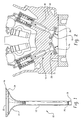
- FIG. 2 is a sectional view illustrating a valve assembly and its associated environment
- FIG. 3 is a sectional view of a lightweight engine poppet valve according to a first embodiment of the present invention
- FIG. 4 is a fragmentary sectional view depicting a portion of the valve stem and the extending portion of the valve head prior to forming the interfitting joint;
- FIG. 5 is a fragmentary sectional view similar to FIG. 4 but depicts the interfitting joint after it is formed;
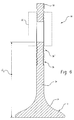
- FIG. 6 is a sectional view of another embodiment of the engine poppet valve according to the present invention.
- FIG. 7 is a sectional view of the engine poppet valve within the hydroforming die according to the present invention.
- FIG. 8 is an enlarged fragmentary sectional view of the hydroforming die and spool member according to the present invention.
- FIG. 1 shows an engine poppet valve, generally designated 10, in accordance with the present invention.
- Poppet valve 10 includes a hollow stem portion 12 and a fillet portion 14 defining a transition region to a valve head portion generally designated 16.
- the fillet 14 tapers concavely inwardly to connect the valve head 16 to the stem 12.
- Stem 12 terminates in a tip portion 18.
- the tip portion 18 includes one or more keeper grooves 20 provided to accommodate a retainer for a valve spring as depicted in Fig. 2.
- the present invention resides in the engine poppet valve 10 being constructed in a manner that mechanically attaches and locks the valve head 16 to the stem portion 12 to form what is referred to herein as a "mechanically locking interfitting joint".
- the term "mechanically locking interfitting joint” as used herein is intended to mean a mechanical attachment between two components which simultaneously is a locking attachment that will not allow the two components to be readily disassembled and then re-assembled as for example in a threaded arrangement.
- the mechanically locking interfitting joint is described in much greater detail later herein and attention will be first directed to the basic structure of an engine poppet valve and its operation.
- the valve head 16 includes a combustion face 22 that faces inwardly into an engine combustion chamber and a valve seat face 24 which is the peripheral surface that engages the engine block or a valve seat insert 26 as seen in Fig. 2.
- the valve head 16 is manufactured with a predetermined diameter that depends upon the given internal combustion engine application. While it is known in this art that an engine poppet valve can be solid, hollow, or partially solid/hollow, the present invention is directed particularly to hollow or partially solid/hollow valves as will be described in further detail herein, to take advantage of unique material properties involved to achieve an optimum light weight valve.
- FIG. 2 for purposes of basic background on the operation of an engine poppet valve, there is shown the engine poppet valve 10 as part of a valve assembly 28 for use in an internal combustion engine.
- the engine poppet valve 10 is reciprocally received within the internal bore of a valve stem guide 30.
- valve stem guide 30 is depicted as a tubular structure which is inserted into the cylinder head 32 of the engine, it should be understood that alternative embodiments include the cylinder head itself functioning as a guide for the valve stem 12 without a separate tubular structure serving as the valve stem guide.
- the valve seat insert 26 cooperatively receives the valve seat face 24 to provide a sealing engagement. Since the operation of a poppet valve and a valve assembly within an internal combustion engine are well known in this art, further description and details concerning its operation are not included herein for the sake of brevity.
- Fig. 3 depicts a sectional view of the assembled engine poppet valve 10 according to a first embodiment of the present invention.
- the valve head 16 is integrally formed via a ceramic forming process, casting process or powder metallurgy with the valve fillet portion 14.
- An extending portion 34 that extends a predetermined distance (d1) from the valve head, is constructed for an interfitting joint 36 at one end 38 of the valve stem portion 12.
- the fillet portion 14 preferably includes a shoulder 39 shown in Fig. 8 positioned so the valve stem portion 12 abuts the fillet portion 14 so that their respective surfaces form a continuous surface as shown in Fig. 1.
- the opposite end of the valve stem portion 12 has the tip portion 18 attached thereto or deep drawn therewith in a manner as is known in this art for attaching valve stem tips.
- Fig. 4 is a fragmentary sectional view of the extending portion 34 of valve head 16 slidably received within end 38 of the valve stem portion 12 prior to forming the interfitting joint 36.
- Extending portion 34 of the valve head 16 is sized to fit within end 38 of valve stem portion 12 in a close fitting relationship.
- Extending portion 34 further includes at least one groove 40, preferably a plurality of grooves 40, and more preferably two grooves 40 axially spaced along its length at the desired location or locations for the interfitting joint 36.
- Fig. 5 shows the mechanically attached interfitting joint 36 after it is formed.
- the interfitting joint 36 mechanically locks the valve head 16 to the valve stem portion 12.
- the preferred method for mechanically making this locking interfitting joint 36 is by means of hydroforming as will be described in further detail later herein.
- the interfitting joint 36 is disposed relatively close to the valve head 16 and as such joint 36 is exposed with the reciprocating action of the engine poppet valve to the high temperatures and corrosive conditions in the combustion chamber. Still, the interfitting joint 36 according to the first embodiment of the present invention is sufficiently strong to withstand the high temperatures and corrosive conditions.
- High temperature fatigue tests conducted at about 1200° F and at about 45% of the ultimate tensile strength (UTS) of the joint at a load of 2.42 KN (KiloNewtons) yielded about 10 7 cycles with the test being suspended but not due to failure. When the load was increased to about 3.00 KN, the test ran about 6,861,322 cycles to failure. When the load was increased even further to about 3.24 KN, the test ran about 3,925,624 cycles to failure. A final test with a load at about 3.78 KN yielded about 229,477 cycles to failure.
- Fig. 6 there is shown another embodiment of the present invention in sectional view where the extending portion 34 extends a distance or length d2 from the valve head.
- This embodiment preferably uses two or more joints 36, 36'.
- Extending portion 34 may be varied to position the interfitting joint 36' at any given distance away from the valve head 16.
- the interfitting joint 36' may be positioned approximately at the bottom of the valve guide 30 which is shown in dashed lines.
- the interfitting joint 36' may be positioned within the valve guide 30.
- a longer extending portion 34 may be desirable in some applications for transferring heat generated by combustion away from the valve 10 through the valve guide 30 for dissipation into the cylinder block 32.
- a poppet valve having a total length of about 12.5 centimeters may have one interfitting joint 36' situated at a distance of about 6.5 cm from the valve head and an interfitting joint 36 located at about 2.5 cm.
- interfitting joint 36' employs two grooves 40 while interfitting joint 36 employs only one groove 40.
- Another example of a poppet valve having a total length of about 12.5 cm. may have a single interfitting joint 36 located 3.5 cm from the valve head. It should be understood that the present invention is not intended to be limited to these examples.
- the present invention employs preferably a solid valve head 16 and extending portion 34 made of preferably a titanium intermetallic material or compound.
- titanium intermetallic material is meant to include but not be limited to the following materials, titanium alloys, titanium boride, titanium aluminide, and titanium.
- the titanium aluminide material is commercially available and preferably comprises titanium with approximately 30 to 50 weight percent aluminum. More preferably, the aluminum content ranges from about 32% to about 35% with small amounts of iron and oxygen.
- the titanium intermetallic material offers a high strength-to-weight ratio as well as excellent sulfidation resistance, good hot hardness, sufficient oxidation resistance, high thermal conductivity and lower thermal expansion.
- valve head 16 while shown as a solid valve head, may be hollowed out to various degrees and depths, and still be in accordance with the present invention.
- HIP hot isostatic pressing
- Ceramic materials include without limitation silicon carbide, silicon nitride, boron nitride, or other suitable oxides or nitrides.
- Ceramics and titanium aluminde are brittle materials.
- the preferred hydroforming process utilizes hydrostatic fluid pressure to apply a uniform compressive radial force to make a locking interfitting joint 36, 36'.
- the process according to the present invention can be used for materials which exhibit brittle behavior typically characterized by ductility levels less than about 2% to about 4% tensile elongation.
- the valve stem portion 12 may be a hollow tube or preferably a deep drawn valve stem made from a wide assortment of materials including but not limited to a titanium alloy such as a titanium aluminide, a stainless steel material such as a 305 or 304 stainless steel that may be machined or deep drawn, a martensitic stainless steel material, or a nickel-based alloy.
- the valve stem portion 12 may be coated with a coating that includes, but is not limited to, chromium plated coating, molybdenum sprayed coating, an Eatonite coating, physical vapor deposition (PVD or chemical vapor deposition (CVD) type coatings or a nitride coating.
- the tip portion 18 preferably is a solid, hardened material such as SAE 1547 or 8645 or Silchrome-1 Steel (Society of Automotive Engineers (SAE) J775 standard) material which is commercially available from commercial suppliers like Charter Steel or Crucible Steel for example.
- SAE Society of Automotive Engineers
- the tip portion 18 may be simply a conventional hardened steel material.
- the tip portion 18 may be attached to the stem portion 12 in any manner known in the art.
- FIG. 7 there is shown in sectional view an apparatus preferably employed to mechanically attach and lock the valve head portion 16 to the valve stem portion 12.
- the preferred method of compressing or uniformly crimping the valve stem portion 12 is using a hydroforming process. While Fig.
- valve stem portion 12 depicts one such device, it is to be understood that the principles of the present invention are applicable to other devices that can uniformly compress valve stem portion 12 in a manner that provides a uniform compressive radial force to form the mechanically locking interfitting joint 36, 36' as described and shown herein.
- Valve head portion 16 is secured within the jaws 45 of die 46 to firmly hold the valve head portion 16 therein.
- the valve stem portion 12 is fitted over the extending portion 34 of valve head portion 16 and is positioned within a pressurization chamber 47 in the die.
- the pressurization chamber 47 is sealed within die 46 with a retaining die member 50 and o-rings (not shown), or any suitable high pressure sealing means.
- the preferred method employs a deformable spool member 48 positioned coaxially over the valve stem portion 12 and over the extending portion 34 at the desired location of the interfitting joint 36 within the pressurization chamber 47.
- the retaining die member 50 positioned over the valve stem portion 12 secures the valve stem 12 and the spool member 48 in place within the die 46.
- the retaining die member 50 is securely fastened to the die 46 by way of clamps (not shown), or other suitable means.
- Die 46 includes a channel 52 which fluidly communicates with the pressurization chamber 47 and the deformable spool member 48 in the selected location for the interfitting joint 36, 36'.
- a high fluid pressure system 54 such as a high pressure pump, forces a fluid 56, preferably oil like a hydraulic or motor oil, under a pressure ranging from about 1850 to about 2200 Kg/mm 2 , preferably about 3 Bar for a TiAl valve, to deform spool member 48 which uniformly compresses the end 38 of the valve stem portion 12 for attaching the extending portion 34 thereto and forms the hydroformed interfitting joint 36, 36'.
- Fig. 8 is an enlarged sectional view of the pressurization chamber 47 and spool member 48.
- the extending portion 34 of valve head 16 as noted previously includes a plurality of grooves 40, and is sized to fit within valve stem portion 12. Shoulder 39 on the fillet portion 14 provides a surface that conforms with the surface of the valve stem portion 12.
- the deformable spool member 48 is preferably made of a polymer material, in particular a high strength elastomer capable of withstanding high pressures and sufficiently resilient to return substantially to its initial form after the hydroforming process, for example, a polytetrafluoroethylene (PTFE) material like Teflon®, a registered trademark of E.I. DuPont de Nemours, Adiprene®, a registered trademark of Uniroyal Chemical Co., Inc. or Curalon M, a trademark of Ihara Chemical Industry, Co.
- PTFE polytetrafluoroethylene
- Teflon® a registered trademark of E.I. DuPont de Nemours, Adiprene®, a registered trademark of Uniroyal Chemical Co., Inc. or Curalon M, a trademark of Ihara Chemical Industry, Co.
- Other high temperature sealing materials such as graphite, blends of polymers and graphite, or the like may also be suitable.
- the edge of the interfitting joint 36 that meets the valve head portion 16 and/or the uniformly crimped areas caused by the grooves 40 may be filled in with brazing or welding.
- the assembly is then finish machined and the stem is coated, for example, by a molybdenum sprayed coating as mentioned earlier.
- the present invention provides a lightweight valve made with components that can be assembled rapidly with the use of a mechanically locking interfitting joint. This makes the lightweight valve more economical to manufacture and still provides good durability.
- the use of the titanium aluminide head yields excellent sulfidation resistance, good hot hardness, sufficient oxidation resistance, and high thermal conductivity along with lower thermal expansion.
Landscapes
- Engineering & Computer Science (AREA)
- Mechanical Engineering (AREA)
- General Engineering & Computer Science (AREA)
- Physics & Mathematics (AREA)
- Geometry (AREA)
- Lift Valve (AREA)
Abstract
Description
- The present invention relates generally to a poppet valve for an internal combustion engine, and more particularly to a lightweight engine poppet valve constructed with a mechanically locking interfitting joint connecting the valve head to the valve stem capable of operating at high temperatures and in a corrosive environment.
- It is well known in the industry that engine poppet valves operate at relatively high temperatures and in corrosive environments. It is further known that exhaust valves operate under more severe conditions than intake valves. The exhaust valves used in diesel and leaded fuel applications, which are considered heavy duty applications, operate in more severe conditions than in other types of internal combustion engines. Engine poppet valves must be able to withstand even the most severe of these conditions and still be durable.
- Efforts are constantly being made to improve the construction, design, and manufacturing techniques of engine poppet valves. These efforts include, but are not limited to, making the valve lighter in weight, more economical to manufacture, and more durable. Lighter poppet valves can offer better fuel economy for a vehicle due to weight considerations, and can be manufactured more cost effectively due to less material employed in the valve. In addition, engine poppet valves can be designed with specific chemical and mechanical properties in mind to withstand the harsh temperature and environmental conditions to which engine poppet valves are subjected. Some of these desired chemical and mechanical properties include, but are not limited to, excellent sulfidation resistance, good hot hardness, sufficient oxidation resistance, optimum thermal resistance, and low thermal expansion.
- The term "lightweight" as employed herein is intended to refer to the physical characteristics of the engine poppet valve and its components that make the engine poppet valve light in weight. The term "lightweight" is also meant to include but not be limited to an ultralight engine poppet valve as that term is defined in U.S. Patent 5, 413,073 which is owned by the assignee of the present invention and is hereby incorporated by reference. The assignee of the present invention also owns U.S. Patents 5,453,314 and 6,263,849, which are both hereby incorporated by reference.
- There is still a desire to make improvements in the manufacturing technique and design of a lightweight engine poppet valve. The engine poppet valve would be constructed in an arrangement that mechanically attaches the valve head to the hollow stem portion in a locking arrangement. Even with this mechanically locking attachment being located in the high temperature and corrosive combustion zone, the lightweight poppet valve would provide excellent sulfidation resistance, good hot hardness, good oxidation resistance, and optimum thermal conductivity with low thermal expansion, optimum thermal resistance, and durability.
- Accordingly, an object of the present invention is to provide an improved lightweight engine poppet valve constructed in a manner that mechanically attaches the valve head to the stem portion in a locking arrangement with an interfitting joint.
- Another object of the present invention is to provide such an engine poppet valve with a valve head made from a titanium intermetallic material that is lightweight, and is durable at optimum temperatures.
- Still another object of the present invention is to provide an engine poppet valve manufactured with a valve head attached to a stem portion by means of a compressed interfitting joint.
- Still another object of the present invention is to provide an improved method for making a lightweight engine poppet valve that mechanically attaches the valve head to the stem portion in a locking arrangement with an interfitting joint.
- These and other objects of the present invention are accomplished with an engine poppet valve comprising a valve head portion, a stem portion, a tip portion and a flared fillet portion of the valve head portion. The flared fillet portion defines a transition region between the valve head portion and the stem portion, and includes an extending portion constructed to form a mechanically locking interfitting joint with the valve stem portion. The valve head portion is made from a lightweight, heat resistant, thermally conductive material.
- Another aspect of the present invention is a method for making an engine poppet valve comprising the steps of forming a valve head from a titanium intermetallic material, providing the valve head with a fillet having an extending portion with a preselected length; providing a tubular stem portion, positioning the extending portion of the valve head inside one end of the tubular stem portion; and compressing the tubular stem portion around the extending portion of the valve head for forming a mechanically locking interfitting joint between the extending portion of the valve head and the tubular stem portion.
- Still another aspect of the present invention is directed to a method for making an engine poppet valve having a valve head that is durable at high temperatures and thermal resistant, and a deep drawn valve stem portion attached to an extending portion of the valve head with a hydroformed interfitting joint which mechanically attaches and locks the valve head to the stem portion.
- The various features of novelty which characterize the invention are pointed out with particularity in the claims annexed to and forming a part of this disclosure. For a better understanding of the invention, its operating advantages, and specific objects attained by its uses, reference is made to the accompanying drawings and descriptive matter in which a preferred embodiment of the invention is illustrated.
- FIG. 1 is an elevated perspective view of an engine poppet valve in accordance with the present invention;
- FIG. 2 is a sectional view illustrating a valve assembly and its associated environment;
- FIG. 3 is a sectional view of a lightweight engine poppet valve according to a first embodiment of the present invention;
- FIG. 4 is a fragmentary sectional view depicting a portion of the valve stem and the extending portion of the valve head prior to forming the interfitting joint;
- FIG. 5 is a fragmentary sectional view similar to FIG. 4 but depicts the interfitting joint after it is formed;
- FIG. 6 is a sectional view of another embodiment of the engine poppet valve according to the present invention;
- FIG. 7 is a sectional view of the engine poppet valve within the hydroforming die according to the present invention; and
- FIG. 8 is an enlarged fragmentary sectional view of the hydroforming die and spool member according to the present invention.
- The Figures are not intended to limit the present invention thereto, and like numerals designate like or similar features throughout the several views. Fig. 1 shows an engine poppet valve, generally designated 10, in accordance with the present invention.
Poppet valve 10 includes ahollow stem portion 12 and afillet portion 14 defining a transition region to a valve head portion generally designated 16. Thefillet 14 tapers concavely inwardly to connect thevalve head 16 to thestem 12.Stem 12 terminates in atip portion 18. Thetip portion 18 includes one ormore keeper grooves 20 provided to accommodate a retainer for a valve spring as depicted in Fig. 2. - The present invention resides in the
engine poppet valve 10 being constructed in a manner that mechanically attaches and locks thevalve head 16 to thestem portion 12 to form what is referred to herein as a "mechanically locking interfitting joint". The term "mechanically locking interfitting joint" as used herein is intended to mean a mechanical attachment between two components which simultaneously is a locking attachment that will not allow the two components to be readily disassembled and then re-assembled as for example in a threaded arrangement. The mechanically locking interfitting joint is described in much greater detail later herein and attention will be first directed to the basic structure of an engine poppet valve and its operation. - The
valve head 16 includes acombustion face 22 that faces inwardly into an engine combustion chamber and avalve seat face 24 which is the peripheral surface that engages the engine block or a valve seat insert 26 as seen in Fig. 2. Thevalve head 16 is manufactured with a predetermined diameter that depends upon the given internal combustion engine application. While it is known in this art that an engine poppet valve can be solid, hollow, or partially solid/hollow, the present invention is directed particularly to hollow or partially solid/hollow valves as will be described in further detail herein, to take advantage of unique material properties involved to achieve an optimum light weight valve. - Still referring to Fig. 2 and for purposes of basic background on the operation of an engine poppet valve, there is shown the
engine poppet valve 10 as part of avalve assembly 28 for use in an internal combustion engine. Theengine poppet valve 10 is reciprocally received within the internal bore of avalve stem guide 30. While thevalve stem guide 30 is depicted as a tubular structure which is inserted into thecylinder head 32 of the engine, it should be understood that alternative embodiments include the cylinder head itself functioning as a guide for thevalve stem 12 without a separate tubular structure serving as the valve stem guide. The valve seat insert 26 cooperatively receives thevalve seat face 24 to provide a sealing engagement. Since the operation of a poppet valve and a valve assembly within an internal combustion engine are well known in this art, further description and details concerning its operation are not included herein for the sake of brevity. - Fig. 3 depicts a sectional view of the assembled
engine poppet valve 10 according to a first embodiment of the present invention. Thevalve head 16 is integrally formed via a ceramic forming process, casting process or powder metallurgy with thevalve fillet portion 14. An extendingportion 34 that extends a predetermined distance (d1) from the valve head, is constructed for an interfittingjoint 36 at oneend 38 of thevalve stem portion 12. Thefillet portion 14 preferably includes ashoulder 39 shown in Fig. 8 positioned so thevalve stem portion 12 abuts thefillet portion 14 so that their respective surfaces form a continuous surface as shown in Fig. 1. The opposite end of thevalve stem portion 12 has thetip portion 18 attached thereto or deep drawn therewith in a manner as is known in this art for attaching valve stem tips. - Fig. 4 is a fragmentary sectional view of the extending
portion 34 ofvalve head 16 slidably received withinend 38 of thevalve stem portion 12 prior to forming the interfittingjoint 36. Extendingportion 34 of thevalve head 16 is sized to fit withinend 38 ofvalve stem portion 12 in a close fitting relationship. Extendingportion 34 further includes at least onegroove 40, preferably a plurality ofgrooves 40, and more preferably twogrooves 40 axially spaced along its length at the desired location or locations for the interfitting joint 36. A force as depicted by arrow A or any suitable tool or device shown in dashed lines and designated 42 in Fig. 4 is employed to provide a uniform compressive or crimping radial force to crimp or compress theend 38 of thevalve stem portion 12 against the extendingportion 34. The force from arrow A ortool 42 is sufficiently strong to force the walls of thevalve stem portion 12 intogrooves 40 on the extendingportion 34 as depicted in Fig. 5 to create the interfitting joint 36 that mechanically attaches and locks thevalve head 16 to thevalve stem portion 12. Thegroove 40 preferably has a contour radius that allows the material ofvalve stem portion 12 to conform to thegroove 40 after compression. The contour radius of the groove is a function of the wall thickness of the tube and its material proprieties. Fig. 5 shows the mechanically attached interfitting joint 36 after it is formed. The interfitting joint 36 mechanically locks thevalve head 16 to thevalve stem portion 12. The preferred method for mechanically making this locking interfitting joint 36 is by means of hydroforming as will be described in further detail later herein. - As is seen in Figs. 1 and 3, the interfitting joint 36 is disposed relatively close to the
valve head 16 and as such joint 36 is exposed with the reciprocating action of the engine poppet valve to the high temperatures and corrosive conditions in the combustion chamber. Still, the interfitting joint 36 according to the first embodiment of the present invention is sufficiently strong to withstand the high temperatures and corrosive conditions. High temperature fatigue tests conducted at about 1200° F and at about 45% of the ultimate tensile strength (UTS) of the joint at a load of 2.42 KN (KiloNewtons) yielded about 107 cycles with the test being suspended but not due to failure. When the load was increased to about 3.00 KN, the test ran about 6,861,322 cycles to failure. When the load was increased even further to about 3.24 KN, the test ran about 3,925,624 cycles to failure. A final test with a load at about 3.78 KN yielded about 229,477 cycles to failure. - Referring now to Fig. 6, there is shown another embodiment of the present invention in sectional view where the extending
portion 34 extends a distance or length d2 from the valve head. This embodiment preferably uses two ormore joints 36, 36'. Extendingportion 34 may be varied to position the interfitting joint 36' at any given distance away from thevalve head 16. As seen in Fig. 6, the interfitting joint 36' may be positioned approximately at the bottom of thevalve guide 30 which is shown in dashed lines. Or, the interfitting joint 36' may be positioned within thevalve guide 30. A longer extendingportion 34 may be desirable in some applications for transferring heat generated by combustion away from thevalve 10 through thevalve guide 30 for dissipation into thecylinder block 32. - The various sizes and lengths of engine poppet valves are dependent upon the given engine application, but it should be readily apparent that a wide variety of thermal and mechanical properties are achievable with the selection of different lengths (d1 or d2) for the extending
portion 34 of thevalve head 16. For illustrative purposes only, a poppet valve having a total length of about 12.5 centimeters may have one interfitting joint 36' situated at a distance of about 6.5 cm from the valve head and an interfitting joint 36 located at about 2.5 cm. In this example, interfitting joint 36' employs twogrooves 40 while interfitting joint 36 employs only onegroove 40. Another example of a poppet valve having a total length of about 12.5 cm. may have a single interfitting joint 36 located 3.5 cm from the valve head. It should be understood that the present invention is not intended to be limited to these examples. - Advantageously, the present invention employs preferably a
solid valve head 16 and extendingportion 34 made of preferably a titanium intermetallic material or compound. As employed herein, the term "titanium intermetallic material" is meant to include but not be limited to the following materials, titanium alloys, titanium boride, titanium aluminide, and titanium. The titanium aluminide material is commercially available and preferably comprises titanium with approximately 30 to 50 weight percent aluminum. More preferably, the aluminum content ranges from about 32% to about 35% with small amounts of iron and oxygen. The titanium intermetallic material offers a high strength-to-weight ratio as well as excellent sulfidation resistance, good hot hardness, sufficient oxidation resistance, high thermal conductivity and lower thermal expansion. As is known in the art of casting metals and their alloys, the shorter casting time for titanium aluminide significantly reduces shrinkage porosity. As a result, one can produce more castings per mold for a significant increase in productivity. The good thermal conductivity of a titanium aluminide valve head allows the valve to operate without coolant in the hollow stem. If desirable for a particular application, coolant may be added to thevalve stem 12. Additionally,valve head 16, while shown as a solid valve head, may be hollowed out to various degrees and depths, and still be in accordance with the present invention. - After casting, the TiAl valve head castings were subjected to hot isostatic pressing (HIP). HIP is a process known in this art and is used to remove centerline shrinkage and close internal porosity.
- Other materials that are suitable for the present invention include without limitation superalloys, preferably cast, and other intermetallics, like NiAl. Ceramic materials are suitable for the present invention, and include without limitation silicon carbide, silicon nitride, boron nitride, or other suitable oxides or nitrides.
- Ceramics and titanium aluminde are brittle materials. Advantageously, the preferred hydroforming process utilizes hydrostatic fluid pressure to apply a uniform compressive radial force to make a locking interfitting joint 36, 36'. The process according to the present invention can be used for materials which exhibit brittle behavior typically characterized by ductility levels less than about 2% to about 4% tensile elongation.
- The valve stem
portion 12 may be a hollow tube or preferably a deep drawn valve stem made from a wide assortment of materials including but not limited to a titanium alloy such as a titanium aluminide, a stainless steel material such as a 305 or 304 stainless steel that may be machined or deep drawn, a martensitic stainless steel material, or a nickel-based alloy. In addition, thevalve stem portion 12 may be coated with a coating that includes, but is not limited to, chromium plated coating, molybdenum sprayed coating, an Eatonite coating, physical vapor deposition (PVD or chemical vapor deposition (CVD) type coatings or a nitride coating. - The
tip portion 18 preferably is a solid, hardened material such as SAE 1547 or 8645 or Silchrome-1 Steel (Society of Automotive Engineers (SAE) J775 standard) material which is commercially available from commercial suppliers like Charter Steel or Crucible Steel for example. Alternatively, thetip portion 18 may be simply a conventional hardened steel material. Thetip portion 18 may be attached to thestem portion 12 in any manner known in the art. - Another aspect of the present invention is directed to a method for making a lightweight engine poppet valve constructed in an arrangement that mechanically attaches and locks the
valve head 16 to thevalve stem 12. The extendingportion 34 of thevalve head 16 is fastened to thevalve stem 12 with a mechanically locking interfitting joint 36, 36'. Referring next to Fig. 7, there is shown in sectional view an apparatus preferably employed to mechanically attach and lock thevalve head portion 16 to thevalve stem portion 12. The preferred method of compressing or uniformly crimping thevalve stem portion 12 is using a hydroforming process. While Fig. 7 depicts one such device, it is to be understood that the principles of the present invention are applicable to other devices that can uniformly compressvalve stem portion 12 in a manner that provides a uniform compressive radial force to form the mechanically locking interfitting joint 36, 36' as described and shown herein. -
Valve head portion 16 is secured within thejaws 45 ofdie 46 to firmly hold thevalve head portion 16 therein. The valve stemportion 12 is fitted over the extendingportion 34 ofvalve head portion 16 and is positioned within apressurization chamber 47 in the die. Thepressurization chamber 47 is sealed withindie 46 with a retainingdie member 50 and o-rings (not shown), or any suitable high pressure sealing means. The preferred method employs adeformable spool member 48 positioned coaxially over thevalve stem portion 12 and over the extendingportion 34 at the desired location of the interfitting joint 36 within thepressurization chamber 47. The retaining diemember 50 positioned over thevalve stem portion 12 secures thevalve stem 12 and thespool member 48 in place within thedie 46. The retaining diemember 50 is securely fastened to the die 46 by way of clamps (not shown), or other suitable means. -
Die 46 includes achannel 52 which fluidly communicates with thepressurization chamber 47 and thedeformable spool member 48 in the selected location for the interfitting joint 36, 36'. A highfluid pressure system 54, such as a high pressure pump, forces a fluid 56, preferably oil like a hydraulic or motor oil, under a pressure ranging from about 1850 to about 2200 Kg/mm2, preferably about 3 Bar for a TiAl valve, to deformspool member 48 which uniformly compresses theend 38 of thevalve stem portion 12 for attaching the extendingportion 34 thereto and forms the hydroformed interfitting joint 36, 36'. - Fig. 8 is an enlarged sectional view of the
pressurization chamber 47 andspool member 48. The extendingportion 34 ofvalve head 16 as noted previously includes a plurality ofgrooves 40, and is sized to fit withinvalve stem portion 12.Shoulder 39 on thefillet portion 14 provides a surface that conforms with the surface of thevalve stem portion 12. - The
deformable spool member 48 is preferably made of a polymer material, in particular a high strength elastomer capable of withstanding high pressures and sufficiently resilient to return substantially to its initial form after the hydroforming process, for example, a polytetrafluoroethylene (PTFE) material like Teflon®, a registered trademark of E.I. DuPont de Nemours, Adiprene®, a registered trademark of Uniroyal Chemical Co., Inc. or Curalon M, a trademark of Ihara Chemical Industry, Co. Other high temperature sealing materials such as graphite, blends of polymers and graphite, or the like may also be suitable. - If desired for further strengthening, the edge of the interfitting joint 36 that meets the
valve head portion 16 and/or the uniformly crimped areas caused by thegrooves 40 may be filled in with brazing or welding. The assembly is then finish machined and the stem is coated, for example, by a molybdenum sprayed coating as mentioned earlier. - In the above manner, the present invention provides a lightweight valve made with components that can be assembled rapidly with the use of a mechanically locking interfitting joint. This makes the lightweight valve more economical to manufacture and still provides good durability. The use of the titanium aluminide head yields excellent sulfidation resistance, good hot hardness, sufficient oxidation resistance, and high thermal conductivity along with lower thermal expansion.
- While specific embodiments of the invention have been shown and described in detail to illustrate the application of the principles of the invention, it will be understood that the invention may be embodied otherwise without departing from such principles.
Claims (20)
- An engine poppet valve (10) comprising a valve head portion (16), a stem portion (12), a tip portion (18), and a flared fillet portion (14) of said valve head portion (16) defining a transition region between said valve head portion (16) and said stem portion (12), said flared fillet portion (14) of said valve head portion (16) including an extending portion (34), said valve head portion (16) being a substantially lightweight, heat resistant material, said stem portion (12) being a hollow tube constructed for a mechanically locking interfitting joint (36) with said extending portion (34) of said flared fillet portion (14).
- An engine poppet valve (10) as recited in Claim 1, wherein said extending portion (34) extends a selected distance from said flared fillet portion (14).
- An engine poppet valve (10) as recited in Claim 2, wherein said mechanically locking interfitting joint (36) comprises a hydroformed joint.
- An engine poppet valve (10) as recited in Claim 1, wherein said valve head portion (16) comprises a material being a member selected from the group consisting of a titanium alloy, titanium borides, titanium-aluminides, a titanium material, superalloys, intermetallics, and ceramics.
- An engine poppet valve (10) as recited in Claim 2, wherein said mechanically locking interfitting joint (36) is disposed proximate said valve head portion (16).
- An engine poppet valve (10) as recited in Claim 2, wherein said mechanically locking interfitting joint (36) is disposed in a valve guide of the cylinder head (30).
- An engine poppet valve (10) as recited in Claim 2, wherein said mechanically locking interfitting joint (36) is disposed at a location proximate a valve guide (30).
- An engine poppet valve (10) as recited in Claim 2, wherein said fillet portion (14) further comprises a shoulder (39) constructed for an abutting relationship with an end (38) of said stem portion (12).
- An engine poppet valve (10) as recited in Claim 1, wherein said stem portion (12) comprises a material being a member selected from the group consisting of a stainless steel material, an aluminum material, a machined or deep drawn 304 or 305 stainless steel material, a titanium-aluminide material, a titanium alloy, a machined or deep drawn martensitic stainless steel material, and a nickel-base alloy.
- An engine poppet valve (10) as recited in Claim 10, wherein said stem portion (12) further comprises a coating being a member selected from the group consisting of a chromium plated coating, molybdenum spray coating, an Eatonite coating, a PVD type coating, CVD type coating, and a nitrided coating.
- An engine poppet valve (10), comprising:a valve head (16) made of an intermetallic compound, said valve head (16) having a fillet portion (14) with an extending portion (34) having a preselected length ; anda valve stem (12), said valve stem (12) being a hollow tube and having one end (38) constructed to slidably receive the extending portion (34) of said valve head (16) and be mechanically locked thereto with an interfitting joint (36), said valve stem (12) further having a tip portion (18) at an opposite end from said valve head (16).
- An engine poppet valve (10) as recited in Claim 11, wherein said stem portion (12) comprises a material being a member selected from the group consisting of a stainless steel material, an aluminum material, a machined or deep drawn 304 or 305 stainless steel material, a titanium-aluminide material, a titanium alloy, a machined or deep drawn martensitic stainless steel material, and a nickel-base alloy.
- An engine poppet valve (10) as recited in Claim 12, wherein said valve stem (12) is mechanically locked to said valve head (16) with a hydroformed interfitting joint (36).
- An engine poppet valve (10) as recited in Claim 13, wherein said extending portion (34) of said valve head (16) further comprises a plurality of grooves (40) axially spaced thereon for forming said mechanically locking interfitting joint (36).
- A method for making a lightweight engine poppet valve (10), comprising the steps of:forming a valve head (16) from an intermetallic material;providing the valve head (16) with a fillet (14) having an extending portion (34) with a preselected length;providing a tubular stem portion (12);positioning the extending portion (34) of the valve head (16) inside one end (38) of the tubular stem portion (12); andcompressing the tubular stem portion (12) around the extending portion (34) of the valve head (16) for forming a mechanically locking interfitting joint (36) between the extending portion (34) of the valve head (16) and the tubular stem portion (12).
- A method according to Claim 15, wherein the positioning step further comprises the steps of:disposing the valve head (16) and tubular stem portion (12) in a die (46);positioning a spool member (48) within the die (46) coaxially surrounding the end (38) of the tubular stem portion (12) positioned around the extending portion (34) of the valve head (16); andsupplying fluid under pressure against the spool member (48) to hydraulically compress the tubular stem portion (12) around the extending portion (34) of the valve head portion (16).
- A method according to Claim 15, wherein the step of the providing the valve head (16) further comprises the step of:providing a plurality of grooves in the extending portion (34).
- A method according to Claim 15, wherein the step of providing the tubular stem portion (12) further includes the step of coating the tubular stem portion (12) with a material being a member selected from the group consisting of a chromium plated coating, a molybdenum spray coating, an Eatonite coating and a nitride coating.
- A method according to Claim 16, wherein the spool member comprises a deformable polymer material.
- A method according to Claim 18, wherein the step of coating further includes the step of coating a valve seat.
Applications Claiming Priority (2)
| Application Number | Priority Date | Filing Date | Title |
|---|---|---|---|
| US350509 | 2003-01-24 | ||
| US10/350,509 US6718932B1 (en) | 2003-01-24 | 2003-01-24 | Lightweight engine poppet valve |
Publications (2)
| Publication Number | Publication Date |
|---|---|
| EP1441111A1 true EP1441111A1 (en) | 2004-07-28 |
| EP1441111B1 EP1441111B1 (en) | 2008-07-30 |
Family
ID=32043075
Family Applications (1)
| Application Number | Title | Priority Date | Filing Date |
|---|---|---|---|
| EP04000068A Expired - Lifetime EP1441111B1 (en) | 2003-01-24 | 2004-01-05 | Light weight engine poppet valve |
Country Status (4)
| Country | Link |
|---|---|
| US (1) | US6718932B1 (en) |
| EP (1) | EP1441111B1 (en) |
| JP (1) | JP2004225700A (en) |
| DE (1) | DE602004015350D1 (en) |
Cited By (1)
| Publication number | Priority date | Publication date | Assignee | Title |
|---|---|---|---|---|
| CN108691598A (en) * | 2017-04-11 | 2018-10-23 | 福特环球技术公司 | Include the internal combustion engine of the valve actuating mechanism with valve spring and the method for installing such valve spring |
Families Citing this family (17)
| Publication number | Priority date | Publication date | Assignee | Title |
|---|---|---|---|---|
| US7540402B2 (en) * | 2001-06-29 | 2009-06-02 | Kva, Inc. | Method for controlling weld metal microstructure using localized controlled cooling of seam-welded joints |
| US7618503B2 (en) * | 2001-06-29 | 2009-11-17 | Mccrink Edward J | Method for improving the performance of seam-welded joints using post-weld heat treatment |
| US7926180B2 (en) * | 2001-06-29 | 2011-04-19 | Mccrink Edward J | Method for manufacturing gas and liquid storage tanks |
| US7475478B2 (en) * | 2001-06-29 | 2009-01-13 | Kva, Inc. | Method for manufacturing automotive structural members |
| JP4298690B2 (en) * | 2005-09-27 | 2009-07-22 | 本田技研工業株式会社 | Engine valve and manufacturing method thereof |
| US7533641B1 (en) | 2006-04-17 | 2009-05-19 | Jason Stewart Jackson | Poppet valve and engine using same |
| US7311068B2 (en) | 2006-04-17 | 2007-12-25 | Jason Stewart Jackson | Poppet valve and engine using same |
| US7540468B2 (en) * | 2006-04-26 | 2009-06-02 | Honeywell International, Inc. | Angled poppet valve manual override mechanism |
| JP2008111396A (en) * | 2006-10-31 | 2008-05-15 | Denso Corp | Manufacturing method of high-pressure fuel pump |
| US20090044780A1 (en) * | 2007-06-25 | 2009-02-19 | Soverns Laura M | Special improved durability engine device for use with stationary power generation systems |
| US20110168123A1 (en) * | 2010-01-12 | 2011-07-14 | Jay Carl Kerr | Engine valve for improved operating efficiency |
| US8833382B2 (en) * | 2010-11-11 | 2014-09-16 | Hamilton Sundstrand Corporation | Article having good wear resistance |
| US9957836B2 (en) | 2012-07-19 | 2018-05-01 | Rti International Metals, Inc. | Titanium alloy having good oxidation resistance and high strength at elevated temperatures |
| DE102013218488A1 (en) * | 2013-09-16 | 2015-03-19 | Mahle International Gmbh | Hollow valve, in particular for an internal combustion engine |
| DE102017202585A1 (en) * | 2016-02-17 | 2017-08-17 | Mahle International Gmbh | Internal combustion engine with at least one cylinder and with at least two hollow-head valves |
| GB2568975A (en) | 2017-10-30 | 2019-06-05 | Eaton Srl | Poppet valve |
| CN113606010A (en) * | 2021-08-26 | 2021-11-05 | 重庆宗申发动机制造有限公司 | Fuel engine valve |
Citations (7)
| Publication number | Priority date | Publication date | Assignee | Title |
|---|---|---|---|---|
| DD238826A1 (en) * | 1985-06-27 | 1986-09-03 | Halberstadt Maschbau | LIFTING VALVE FOR INTERNAL COMBUSTION ENGINES WITH CORROSION PROTECTION HOLES |
| EP0296619A1 (en) * | 1987-06-25 | 1988-12-28 | Kawasaki Jukogyo Kabushiki Kaisha | Composite valve for reciprocating engines and method for manufacturing the same |
| JPH025704A (en) * | 1988-06-24 | 1990-01-10 | Hino Motors Ltd | Intake/exhaust valve for engine and manufacture thereof |
| US5458314A (en) * | 1993-04-01 | 1995-10-17 | Eaton Corporation | Temperature control in an ultra light engine valve |
| US5771852A (en) * | 1997-03-04 | 1998-06-30 | Trw Inc. | Poppet valve with embossed neck structure |
| JP2000045730A (en) * | 1998-07-31 | 2000-02-15 | Isao Shirayanagi | Poppet valve body |
| DE10031927A1 (en) * | 2000-06-30 | 2002-01-24 | Daimler Chrysler Ag | Multi-part valve, for an IC motor, has a lightweight valve head bonded to a lightweight valve shaft by friction welding using low-cost components giving high thermal and mechanical resistance |
Family Cites Families (8)
| Publication number | Priority date | Publication date | Assignee | Title |
|---|---|---|---|---|
| JPS58151306U (en) | 1982-04-05 | 1983-10-11 | 日産自動車株式会社 | Internal combustion engine intake and exhaust valves |
| JPH05202706A (en) | 1992-01-29 | 1993-08-10 | Daido Steel Co Ltd | Engine valve and manufacture thereof |
| US5413073A (en) | 1993-04-01 | 1995-05-09 | Eaton Corporation | Ultra light engine valve |
| US5441235A (en) | 1994-05-20 | 1995-08-15 | Eaton Corporation | Titanium nitride coated valve and method for making |
| US5517956A (en) | 1994-08-11 | 1996-05-21 | Del West Engineering, Inc. | Titanium engine valve |
| US5823158A (en) | 1997-03-04 | 1998-10-20 | Trw Inc. | Engine valve and method for making the same |
| DE59707222D1 (en) | 1997-08-19 | 2002-06-13 | Trw Deutschland Gmbh | Hollow valve for internal combustion engines |
| US6263849B1 (en) | 1999-07-20 | 2001-07-24 | Eaton Corporation | Ultra light engine valve and method of welding cap thereto |
-
2003
- 2003-01-24 US US10/350,509 patent/US6718932B1/en not_active Expired - Lifetime
-
2004
- 2004-01-05 EP EP04000068A patent/EP1441111B1/en not_active Expired - Lifetime
- 2004-01-05 DE DE602004015350T patent/DE602004015350D1/en not_active Expired - Lifetime
- 2004-01-23 JP JP2004015155A patent/JP2004225700A/en active Pending
Patent Citations (7)
| Publication number | Priority date | Publication date | Assignee | Title |
|---|---|---|---|---|
| DD238826A1 (en) * | 1985-06-27 | 1986-09-03 | Halberstadt Maschbau | LIFTING VALVE FOR INTERNAL COMBUSTION ENGINES WITH CORROSION PROTECTION HOLES |
| EP0296619A1 (en) * | 1987-06-25 | 1988-12-28 | Kawasaki Jukogyo Kabushiki Kaisha | Composite valve for reciprocating engines and method for manufacturing the same |
| JPH025704A (en) * | 1988-06-24 | 1990-01-10 | Hino Motors Ltd | Intake/exhaust valve for engine and manufacture thereof |
| US5458314A (en) * | 1993-04-01 | 1995-10-17 | Eaton Corporation | Temperature control in an ultra light engine valve |
| US5771852A (en) * | 1997-03-04 | 1998-06-30 | Trw Inc. | Poppet valve with embossed neck structure |
| JP2000045730A (en) * | 1998-07-31 | 2000-02-15 | Isao Shirayanagi | Poppet valve body |
| DE10031927A1 (en) * | 2000-06-30 | 2002-01-24 | Daimler Chrysler Ag | Multi-part valve, for an IC motor, has a lightweight valve head bonded to a lightweight valve shaft by friction welding using low-cost components giving high thermal and mechanical resistance |
Non-Patent Citations (2)
| Title |
|---|
| PATENT ABSTRACTS OF JAPAN vol. 0141, no. 35 (M - 0949) 14 March 1990 (1990-03-14) * |
| PATENT ABSTRACTS OF JAPAN vol. 2000, no. 05 14 September 2000 (2000-09-14) * |
Cited By (2)
| Publication number | Priority date | Publication date | Assignee | Title |
|---|---|---|---|---|
| CN108691598A (en) * | 2017-04-11 | 2018-10-23 | 福特环球技术公司 | Include the internal combustion engine of the valve actuating mechanism with valve spring and the method for installing such valve spring |
| CN108691598B (en) * | 2017-04-11 | 2022-01-14 | 福特环球技术公司 | Internal combustion engine with valve spring and method for mounting such valve spring |
Also Published As
| Publication number | Publication date |
|---|---|
| JP2004225700A (en) | 2004-08-12 |
| DE602004015350D1 (en) | 2008-09-11 |
| US6718932B1 (en) | 2004-04-13 |
| EP1441111B1 (en) | 2008-07-30 |
Similar Documents
| Publication | Publication Date | Title |
|---|---|---|
| US6718932B1 (en) | Lightweight engine poppet valve | |
| JP4801324B2 (en) | Lightweight composite poppet valve for engines | |
| US4834036A (en) | Composite valve for reciprocating engines and method for manufacturing the same | |
| US5823158A (en) | Engine valve and method for making the same | |
| JP4898659B2 (en) | High strength steel cylinder liner for diesel engine | |
| US6167856B1 (en) | Low friction cam shaft | |
| JPS62107216A (en) | Valve seat insert and cylinder head comprising same | |
| JPS60103082A (en) | Metal ceramic bonded body and manufacture | |
| US5794943A (en) | Piston rings particularly suited for use with ceramic matrix composite pistons and cylinders | |
| US5816211A (en) | Fiber reinforced ceramic matrix composite piston and cylinder/sleeve for an internal combustion engine | |
| US5773734A (en) | Nitrided powdered metal piston ring | |
| US4465040A (en) | Valve guide insert | |
| EP1375841A2 (en) | powder metal valve seat insert | |
| CA2678752A1 (en) | Method for the production of a high-pressure accumulator pipe made of steel for fuel injection systems and high-pressure accumulator pipe produced according to this method | |
| US5860401A (en) | Bonded valve seat and method | |
| US4810585A (en) | Metal-ceramic composite bodies and a method for manufacturing the same | |
| US6148785A (en) | Pistons and cylinders made of carbon-carbon composite materials | |
| JP6905689B2 (en) | Sliding members and sliding members of internal combustion engines | |
| US5542315A (en) | Elephant's foot adjusting screw assembly for internal combustion engine | |
| US6044819A (en) | Pistons and cylinders made of carbon-carbon composite materials | |
| WO2010014012A1 (en) | Cylinder head with valve seat and method for the production thereof | |
| EP0682171A2 (en) | Valve crosshead assembly with wear-reducing contact pad | |
| CN110248752B (en) | Sliding member and sliding member of internal combustion engine | |
| JPH03260362A (en) | Internal-combustion engine and its factors | |
| US5809644A (en) | Valve lifter |
Legal Events
| Date | Code | Title | Description |
|---|---|---|---|
| PUAI | Public reference made under article 153(3) epc to a published international application that has entered the european phase |
Free format text: ORIGINAL CODE: 0009012 |
|
| AK | Designated contracting states |
Kind code of ref document: A1 Designated state(s): AT BE BG CH CY CZ DE DK EE ES FI FR GB GR HU IE IT LI LU MC NL PT RO SE SI SK TR |
|
| AX | Request for extension of the european patent |
Extension state: AL LT LV MK |
|
| 17P | Request for examination filed |
Effective date: 20050127 |
|
| 17Q | First examination report despatched |
Effective date: 20050302 |
|
| AKX | Designation fees paid |
Designated state(s): DE GB |
|
| 17Q | First examination report despatched |
Effective date: 20050302 |
|
| GRAC | Information related to communication of intention to grant a patent modified |
Free format text: ORIGINAL CODE: EPIDOSCIGR1 |
|
| GRAJ | Information related to disapproval of communication of intention to grant by the applicant or resumption of examination proceedings by the epo deleted |
Free format text: ORIGINAL CODE: EPIDOSDIGR1 |
|
| GRAP | Despatch of communication of intention to grant a patent |
Free format text: ORIGINAL CODE: EPIDOSNIGR1 |
|
| GRAS | Grant fee paid |
Free format text: ORIGINAL CODE: EPIDOSNIGR3 |
|
| GRAA | (expected) grant |
Free format text: ORIGINAL CODE: 0009210 |
|
| AK | Designated contracting states |
Kind code of ref document: B1 Designated state(s): DE GB |
|
| REG | Reference to a national code |
Ref country code: GB Ref legal event code: FG4D |
|
| REF | Corresponds to: |
Ref document number: 602004015350 Country of ref document: DE Date of ref document: 20080911 Kind code of ref document: P |
|
| PLBE | No opposition filed within time limit |
Free format text: ORIGINAL CODE: 0009261 |
|
| STAA | Information on the status of an ep patent application or granted ep patent |
Free format text: STATUS: NO OPPOSITION FILED WITHIN TIME LIMIT |
|
| 26N | No opposition filed |
Effective date: 20090506 |
|
| GBPC | Gb: european patent ceased through non-payment of renewal fee |
Effective date: 20090105 |
|
| PG25 | Lapsed in a contracting state [announced via postgrant information from national office to epo] |
Ref country code: GB Free format text: LAPSE BECAUSE OF NON-PAYMENT OF DUE FEES Effective date: 20090105 |
|
| REG | Reference to a national code |
Ref country code: DE Ref legal event code: R082 Ref document number: 602004015350 Country of ref document: DE Ref country code: DE Ref legal event code: R081 Ref document number: 602004015350 Country of ref document: DE Owner name: EATON INTELLIGENT POWER LIMITED, IE Free format text: FORMER OWNER: EATON CORP., CLEVELAND, OHIO, US |
|
| PGFP | Annual fee paid to national office [announced via postgrant information from national office to epo] |
Ref country code: DE Payment date: 20221220 Year of fee payment: 20 |
|
| P01 | Opt-out of the competence of the unified patent court (upc) registered |
Effective date: 20230521 |
|
| REG | Reference to a national code |
Ref country code: DE Ref legal event code: R071 Ref document number: 602004015350 Country of ref document: DE |