Technical Field
The present invention relates to a pneumatic tire which is low in
rolling resistance.
Background Art
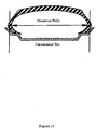
The shape of a conventional pneumatic tire is shown in Fig. 17. As
shown in the same figure, the conventional pneumatic tire has a maximum
width at vertically intermediate side portions thereof. By adopting such a
shape wherein the radius of curvature of each side portion changes gently,
each side portion has a tension induced by the internal air pressure of the
tire.
In connection with a rolling resistance, it is generally known that a
tire having a large value of Tb/Ts is better in terms of a relation between
belt tension (Tb) and side tension (Ts) both based on air pressure. That is,
a tire having a high belt tension and a low side tension is preferred for
reducing a rolling resistance.
The reason is that, at a high belt tension, the roundness, which may
also be designated roundness deviation, of a belt layer at a tire-ground
contact portion is maintained during rolling of the tire under a load. While
the roundness of the belt layer is maintained, a flexural deformation in the
circumferential direction of the belt layer which causes the belt layer to
change from a circular shape to a flat shape is small. Consequently, a
shear strain deformation, which occurs between cross layers of an angle belt
used in an ordinary radial tire, becomes smaller. This shear strain
deformation between cross layers of a belt causes a delay in the occurrence
of a stress during rolling, which is attributable to the fact that rubber
sandwiched in between the cross layers or rubber present thereabouts
possesses viscoelasticity, and this delay acts as a loss and as one cause of a
rolling resistance.
Thus, deforming the belt layer so as to maintain the roundness of
the same layer is one method for lowering a rolling resistance. Further, it
is evident that making the value of Tb large and that of Ts small is desirable
for attaining such a deformation.
For attaining such a tension distribution, various studies have so far
been made about a sectional shape of a tire. For example, in Japanese
Patent Laid-Open No. S52(1977)-79402 Publication there is a description on
a sectional shape of a tire.
In the Japanese Patent Laid-Open No. S52(1977)-79402 publication
there is described a structure wherein a maximum structure width of a
wheel with a pneumatic tire lies in the vicinity of tire beads.
However, in the pneumatic tire structure disclosed in the Japanese
Patent Laid-Open No. S52(1977)-79402 publication, a limit is made to the
way of thinking that control is performed in terms of tension distribution,
and therefore a lowering of a rolling resistance cannot be attained to a
satisfactory extent.
Accordingly, it is an object of the present invention to provide an
assembly of a tire and a rim, and a tire, capable of lowering a rolling
resistance.
Disclosure of Invention
According to the present invention as described in claim 1, a tire-rim
assembly includes: a carcass ply having an increased width part and drawn
parts, the increased width part increasing in width gradually from a
maximum diameter portion of a tire toward the center of the tire, the drawn
parts being contiguous to maximum width portions of the increased width
part and becoming smaller in width than the maximum width portions; a
rim adapted to prevent the drawn parts from swelling toward the center of
the tire; and a belt layer having a cord disposed on an outer periphery of the
carcass ply in a direction crossing the carcass ply.
In the tire-rim assembly constructed as above, the internal pressure
of the tire directs radially outwards of the tire at an increased width part
and therefore acts so as to increase the belt tension in the belt layer.
Besides, since drawn parts are prevented by the rim from swelling toward
the center of the tire, it is possible to prevent a lowering of belt tension
which is caused by swelling of the drawn parts toward the center of the tire.
With a consequent increase of belt tension, the roundness, which
may also be designated roundness deviation, at a tire-ground contact
portion is maintained during rolling of the tire under a load. As a result, a
rolling resistance of the tire-rim assembly is lowered.
The present invention as described in claim 2, is a tire-rim assembly
according to claim 1, wherein the angle between the increased width part
and each the drawn part is in the range of 30 to 75 degrees.
The present invention as described in claim 3, is a tire-rim assembly
according to claim 1, wherein the drawn parts each have a substantially
horizontal portion contiguous to the increased width part.
Te present invention as described in claim 4, is a tire-rim assembly
according to claim 3, wherein the rim is in contact with substantially the
whole of the horizontal portions of the drawn parts and has flange parts
disposed on the center side of the tire with respect to the horizontal portions
of the drawn parts.
According to the tire-rim assembly constructed as above, it is
possible to prevent the drawn parts from swelling toward the center of the
tire.
According to the present invention as described in claim 5, atire-rim
assembly according to claim 3 or claim 4, further includes beads disposed at
end portions of the carcass ply, and wherein the radius of curvature of each
of first portions where the horizontal portions of the drawn parts and the
increased width part are contiguous to each other and the radius of
curvature of each of second portions where the horizontal portions of the
drawn parts and the beads are contiguous to each other, are extremely small
in comparison with the maximum diameter of the tire, and the center of
curvature radius of each of the first portions lies inside the carcass ply,
while the center of curvature radius of each of the second portions lies
outside the carcass ply.
According to the tire-rim assembly constructed as above, since first
and second portions are small in the radius of curvature, a flexural
deformation is concentrated thereon, whereby it is possible to maintain the
roundness of the belt layer, thus leading to a lowering of a rolling resistance.
Besides, since the first portions are deformed outside the carcass ply
with the second portions as fulcrums, it is possible to ensure a sufficient
space for flexural deformation.
The present invention as described in claim 6, is a tire-rim assembly
according to claim 5, wherein the increased width part has a maximum
diameter part having a diameter almost equal to the maximum diameter
and connection parts for connection between the maximum diameter part
and the drawn parts, and the belt layer is disposed so as to extend along the
maximum diameter part and so as not to extend along the connection parts.
The present invention as described in claim 7, is a tire-rim assembly
according to claim 6, wherein the portion of the belt layer disposed so as not
to extend along the maximum diameter part faces the outside of the tire
with respect to the maximum diameter part.
According to the present invention as described in claim 8, a tire-rim
assembly according to claim 3, further includes beads disposed radially
inwards of the tire with respect to the horizontal portions, and wherein the
drawn parts each have a bead winging portion, the bead winding portion
passing inside of the associated one of the beads in the tire width direction,
then passing inside of the bead in the radial direction of the tire, further
passing outside of the bead in the tire width direction, and being disposed
along the associated one of the horizontal portions.
According to the present invention as described in claim 9, a tire-rim
assembly according to claim 3, further includes beads disposed radially
inwards of the tire with respect to the horizontal portions, and wherein the
drawn parts each have a bead winding portion, the bead winding portion
passing outside of the associated one of the beads in the tire width direction,
then passing inside of the bead in the radial direction of the tire, and further
passing inside of the bead in the tire width direction, and being disposed
along the associated one of the horizontal portions.
According to the present invention as described in claim 10, a tire-rim
assembly according to claim 3, further includes a hard member, the
hard member being disposed in an area from each of the horizontal portions
up to a height, the height being smaller than one-third of the height from
the maximum width portion of the increased width part to the outermost
portion of the tire.
The present invention as described in claim 11, is a tire-rim
assembly according to claim 5, wherein the hard member is disposed in each
of the second portions.
According to the present invention as described in claim 12, a tire-rim
assembly according to claim 11, further includes a hard member, the
hard member being disposed in an area from each of the horizontal portions
up to a height, the height being smaller than one-third of the height from
the maximum width portion of the increased width part to the outermost
portion of the tire, the hard member being independent of the hard member
disposed in each of the second portions.
According to the present invention as described in claim 13, a tire-rim
assembly according to claim 3, further includes an expansion
suppressing member for suppressing a radial expansion of the tire, the
expansion suppressing member being disposed in an area from each of the
horizontal portions up to a height, the height being smaller than one-third
of the height from the maximum width portion of the increased width part
to the outermost portion of the tire.
According to the present invention as described in claim 14, a tire
includes: a carcass ply, the carcass ply having an increased width part and
drawn parts, the increased width part increasing in width from a maximum
diameter portion of the tire toward the center of the tire, the drawn parts
decreasing in width from a maximum width portion of the increased width
part; and a belt layer having a cord disposed on an outer periphery of the
carcass ply in a direction crossing the carcass ply, wherein the drawn parts
are prevented from swelling toward the center of the tire.
The present invention as described in claim 15, is a tire according to
claim 14, wherein the angle between the increased width part and each the
drawn part is in the range of 30 to 75 degrees.
The present invention as described in claim 16, is a tire according to
claim 14, wherein the drawn parts each have a substantially horizontal
portion contiguous to the increased width part.
According to the present invention as described in claim 17, a tire
according to claim 16, further includes beads disposed at end portions of the
carcass ply, and wherein the radius of curvature of each of first portions
where the horizontal portions of the drawn parts and the increased width
part are contiguous to each other and the radius of curvature of each of
second portions where the horizontal portions of the drawn parts and the
beads are contiguous to each other, are extremely small in comparison with
the maximum diameter of the tire, and the center of curvature radius of
each of the first portions lies inside the carcass ply, while the center of
curvature radius of each of the second portions lies outside the carcass ply.
The present invention as described in claim 18, is a tire according to
claim 17, wherein the increased width part has a maximum diameter part
having a diameter almost equal to the maximum diameter and connection
parts for connection between the maximum diameter part and the drawn
parts, and the belt layer is disposed so as to extend along the maximum
diameter part and so as not to extend along the connection parts.
The present invention as described in claim 19, is a tire according to
claim 18, wherein the portion of the belt layer disposed so as not to extend
along the maximum diameter part faces the outside of the tire with respect
to the maximum diameter part.
According to the present invention as described in claim 20, a tire
according to claim 16, further includes beads disposed radially inwards of
the tire with respect to the horizontal portions, and wherein the drawn
parts each have a bead winging portion, the bead winding portion passing
inside of the associated one of the beads in the tire width direction, then
passing inside of the bead in the radial direction of the tire, further passing
outside of the bead in the tire width direction, and being disposed along the
associated one of the horizontal portions.
According to the present invention as described in claim 21, a tire
according to claim 16, further includes beads disposed radially inwards of
the tire with respect to the horizontal portions, and wherein the drawn
parts each have a bead winding portion, the bead winding portion passing
outside of the associated one of the beads in the tire width direction, then
passing inside of the bead in the radial direction of the tire, and further
passing inside of the bead in the tire width direction, and being disposed
along the associated one of the horizontal portions.
According to the present invention as described in claim 22, a tire
according to claim 16, further includes a hard member, the hard member
being disposed in an area from each of the horizontal portions up to a height,
the height being smaller than one-third of the height from the maximum
width portion of the increased width part to the outermost portion of the tire.
The present invention as described in claim 23, is a tire according to
claim 17, wherein the hard member is disposed in each of the second
portions.
According to the present invention as described in claim 24, a tire
according to claim 23, further includes a hard member, the hard member
being disposed in an area from each of the horizontal portions up to a height,
the height being smaller than one-third of the height from the maximum
width portion of the increased width part to the outermost portion of the tire,
the hard member being independent of the hard member disposed in each of
the second portions.
According to the present invention as described in claim 25, a tire
according to claim 16, further includes an expansion suppressing member
for suppressing a radial expansion of the tire, the expansion suppressing
member being disposed in an area from each of the horizontal portions up to
a height, the height being smaller than one-third of the height from the
maximum width portion of the increased width part to the outermost
portion of the tire.
Brief Description of Drawings
Fig. 1 is a radial sectional view of a tire-rim assembly 1 according to
the first embodiment.
Fig. 2 is an enlarged view of the carcass ply 10 in the vicinity of the
drawn parts 14.
Fig. 3 illustrates an internal pressure of a conventional tire (Fig.
3(a)) and that of the tire of the first embodiment (Fig. 3(b)).
Fig. 4 shows shapes of the tire of the first embodiment both in a
load-free condition and a loaded condition of the tire.
Fig. 5 shows shapes of the tires of the Examples, wherein Figs. 5(a),
5(b), and 5(c) illustrate the tires of Examples 1, 2, and 3, respectively.
Fig. 6 illustrates a load-free condition of an air-inflated tire 2 (the
tire shape is determined by the internal pressure of the tire) and a loaded
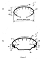
condition of the tire, wherein Fig. 6(a) illustrates a conventional tire 2 which
has a maximum width at an approximately intermediate position of side
portions, while Fig. 6(b) illustrates the tire 2 according to the first
embodiment.
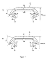
Fig. 7 is a sectional view in a radial direction of a tire 2 according to
a second embodiment of the present invention, showing a horizontal state of
a belt layer 30 (Fig. 7(a)) and a jumped-up state of the belt layer (Fig. 7(b)).
Fig. 8(a) represents a vector of a force acting on an inner surface of
the tire 2 in the first embodiment (the force acting when the tire is charged
with air), and Fig. 8(b) shows how the tire 2 is deformed upon operation
thereon of such a force as shown in Fig. 8(a).
Fig. 9 shows a deformed state of the tire 2 under a lateral force
applied thereto by turning a steering wheel.
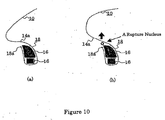
Fig. 10 shows beads 16 and the vicinity thereof in the carcass ply 10
used in the first embodiment, wherein Fig. 10(a) shows a state before the
tire is charged with air, and wherein Fig. 10(b) shows a state after the tire
has been charged with air.
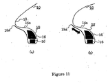
Fig. 11 illustrates beads 16 and the vicinity thereof in a carcass ply
10 according to the third embodiment, wherein Fig. 11(a) shows a state
before the tire is charged with air, and wherein Fig. 11(b) shows a state after
the tire has been charged with air.
Fig. 12 is a explanatory drawing of RZ shear.
Fig. 13 illustrates beads 16 and the vicinity thereof in the carcass
ply 10 according to this fourth embodiment, wherein Fig. 13(a) shows a state
before the tire is charged with air, and wherein Fig. 13(b) shows a state
after the tire has been charged with air.
Fig. 15 is a schematic sectional view in a radial direction of a tire 2
according to a fifth embodiment of the present invention.
Fig. 16 illustrates states of deformation of the tire 2 in the absence
(Fig. 16(a)) and presence (Fig. 16(b)) of the expansive deformation
suppressing member 50.
Fig. 17 is a radial sectional view showing the shape of a conventional
pneumatic tire.
Best Mode for Carrying Out the Invention
Embodiments of the present invention will be described hereinunder
with reference to the accompanying drawings.
First Embodiment
The construction of a first embodiment of the present invention will
now be described. Fig. 1 is a radial sectional view of a tire-rim assembly 1
according to the first embodiment. The tire-rim assembly 1 has a carcass
ply 10, a rim 20, and a belt layer 30.
The carcass ply 10 has an increased width part 12, drawn parts 14,
and beads 16.
The increased width part 12 increases in width from a maximum
diameter Dmax portion of the tire toward the center of the tire, and becomes
maximum in width, Wmax, at its end portions.
The drawn parts 14 are contiguous to the maximum width portions
of the increased width part 12 and become smaller in width gradually from
the maximum width portions. The drawn parts 14 have horizontal portions
14a respectively. The horizontal portions 14a are substantially horizontal
portions contiguous to the end portions of the increased width part 12. The
horizontal portions 14a may be horizontal or may have a small angle. It is
preferable that the length L of each horizontal portion 14a be 0.01 Wmax or
more.
The beads 16 are provided at end portions of the carcass ply 10.
The rim 20, to which the carcass ply 10 is attached, prevents the
drawn parts 14 from swelling toward the center of the tire. The rim 20 has
flange parts 22. The flange parts 22 are in contact with substantially the
whole areas of the horizontal portions 14a of the drawn parts 14. Besides,
the flange parts 22 are disposed on the center side of the tire with respect to
the horizontal portions 14a of the drawn parts 14. However, the flange
parts 22 may be located near or in contact with second portions 17 which
will be described later.
At each of the portions where the increased width portion 12 takes
the maximum width Wmax, the height H2 thereof from the associated
flange part 22 is smaller than the height H1 from the maximum width
Wmax portion to the maximum diameter portion Dmax of the tire.
Preferably, the ratio of H2/H1 is 0.3 or less.
In the belt layer 30, a cord is disposed on an outer periphery of the
carcass ply 10 in a direction crossing the carcass ply.
Fig. 2 is an enlarged view of the carcass ply 10 in the vicinity of the
drawn parts 14. The horizontal portion 14a of each drawn part 14 and the
increased width part 12 are contiguous to each other at a first portion 13.
The horizontal portion 14a of each drawn part 14 and the associated bead 16
are contiguous to each other at the associated second portion 17. A radius
of curvature R1 of the first portion 13 and a radius of curvature R2 of the
second portion 17 are extremely small in comparison with the maximum
diameter Dmax of the tire. It is preferable that R1 and R2 be each
0.07Dmax/2 or less. A curvature radius center of the first portion 13 lies in
the interior of the carcass ply 10 and that of the second portion 17 lies in the
exterior of the carcass ply. In the vicinity of the first portion 13, the angle
between the associated drawn part 14 and the increased width part 12 is
preferably 90° or less.
It is particularly preferable that the angle be in the range of 30° to
75°. If the angle is smaller than 30°, the carcass 10 is apt to rupture due
to deflection under a load. If the angle exceeds 75°, the effect of
decreasing the rolling resistance is not exhibited to a satisfactory extent
because the easiness of bending (a lowering of side tension Ts) is insufficient.
Thus, if the angle is in the range of 30° to 75°, the carcass ply 10 is
difficult to rupture and the effect of decreasing the rolling resistance
remains outstanding.
Next, a description will be given below about the operation of the
first embodiment.
Fig. 3 illustrates an internal pressure of a conventional tire (Fig.
3(a)) and that of the tire of the first embodiment (Fig. 3(b)). The tire is
generally filled with air and an internal pressure is developed.
In the conventional tire, as shown in Fig. 3(a), at a portion 10a (the
upper side in Fig. 3(a)) located outside the maximum width Wmax portion in
the carcass ply 10, an internal pressure of the tire acts in directions
indicated by solid-line arrows. As is apparent from Fig. 3(a), the internal
pressure of the tire causes the belt layer 30 to swell radially outwards of the
tire. This leads to increasing the belt tension in the belt layer 30. At a
high belt tension, the roundness, which may also be designated roundness
deviation, at the tire-ground contact portion is maintained during rolling of
the tire under a load. Consequently, the rolling resistance of the tire-rim
assembly is decreased.
Also in the tire of the first embodiment of the present invention, as
shown in Fig. 3(b), an internal pressure imposed on the increased width
part 12 of the carcass ply 10 acts in directions indicated by solid-line arrows.
Thus, the internal pressure of the tire causes the belt layer 30 of the tire to
swell radially outwards of the tire. This also leads to increasing the belt
tension in the belt layer 30.
In the conventional tire, however, for bead portions 10b (the lower
side in Fig. 3(a)) located inside the maximum width Wmax portion in the
carcass ply 10, the internal pressure of the tire acts in directions indicated
by dotted-line arrows. As is apparent from Fig. 3(a), the internal pressure
of tire causes the belt layer 30 of the tire to swell radially inwards of the tire
(downward in Fig. 3(a)). This leads to decreasing the belt tension in the
belt layer 30, which is an obstacle to attaining a lowering in rolling
resistance of the tire-rim assembly.
On the other hand, in the tire of the first embodiment of the present
invention, as shown in Fig. 3(b), the internal pressure imposed on the drawn
parts 14 of the carcass ply 10 acts in directions indicated by dotted-line
arrows. However, the horizontal portions 14a of the drawn parts 14 are
prevented by the flange parts 22 of the rim 20 from swelling radially
inwards of the tire (downward in Figs. 3(b)). More specifically, the second
portion 17 on the left lower side (the right lower side) in Fig. 3(b) is pushed
to the left lower side (the right lower side) with the internal pressure
indicated by a dotted-line arrow. In this case, if the associated flange part
22 is not present, the shape of the horizontal portion 14a is no longer
horizontal. However, since the flange part 22 is in contact with
substantially the whole area of the horizontal portion 14a and is located
near or in contact with the second portion 17, the shape of the horizontal
portion 14a is kept horizontal and hence a decrease of belt tension in the
belt layer 30 is prevented. Consequently, a lowering in rolling resistance of
the tire-rim assembly is not obstructed.
To prevent deformation of the second portions 17, the second
portions may be formed of a hard member instead of using the flange parts
22. The hard member is, for example, such a hard rubber as satisfies the
relationship of 0.5<E<3.5 wherein E stands for an elastic modulus (kg/mm2).
In the case where a greater importance is attached to restraint of the second
portions 17 for maintaining the shape of the horizontal portions 14a
horizontal, there also may be used a bead-like member.
Fig. 4 shows shapes of the tire of the first embodiment both in a
load-free condition and a loaded condition of the tire. The first and second
portions 13, 17 are positioned near the flange parts 22. In the drawings
which follow, the belt layer 30 is omitted its illustration. Thus, even when
the tire is charged with air and an internal pressure is developed,
deformation of the tire is suppressed by the flange parts 22, so that the
radius of curvature of the first portions 13 and that of the second portions 17
remain extremely small in comparison with the maximum diameter Dmax
of the tire. The dotted line in Fig. 4 represents a loaded shape of the tire.
When a load is imposed on the tire, the first portions 13 are deformed
inwards (downwards in Fig. 4) with the second portions 17 as fulcrums, so
that flexural deformations under a load are concentrated near the first and
second portions 13, 17. Consequently, as the deformation of the tire as a
whole, the roundness in the circumferential direction of the belt can be
maintained. Besides, since the first portions 13 are positioned outside the
second portions 17 in the width direction, a flexural deformation of the first
portions 13 under a load is performed outside the carcass ply 10, thus
ensuring a sufficient space for the deformation.
According to this first embodiment, in the increased width part 12,
the internal pressure of the tire directs radially outwards of the tire and
hence acts to increase the belt tension in the belt layer 30. Moreover, since
the horizontal portions 14a of the drawn parts 14 are prevented by the
flange parts 22 of the rim 20 from swelling toward the center of the tire, it is
possible to prevent a lowering of belt tension which is caused by swelling of
the drawn parts 14 toward the tire center.
Accordingly, with an increase of belt tension, the roundness, which
also may be designated roundness deviation, at the tire-ground contact
portion is maintained during rolling under a load of the tire. Thus, a
lowering in rolling resistance of the tire-rim assembly results.
Further, since the radii of curvature R1, R2 of the first and second
portions 13, 17 are small, flexural deformations are concentrated on both
portions when the tire is loaded, whereby the roundness of the belt layer 30
can be retained, thus leading to a lowering of rolling resistance.
Additionally, since the first portions 13 are deformed outside the
carcass ply 10 with the second portions 17 as fulcrums, it is possible to
ensure a sufficient space for flexural deformations.
EXAMPLES
The following tires are presented as Examples 1, 2, and 3.
Fig. 5 shows shapes of the tires of the Examples. More specifically,
Figs. 5(a), 5(b), and 5(c) illustrate the tires of Examples 1, 2, and 3,
respectively, provided the rim 20 is not shown.
Table 1 below compares rolling resistance coefficients of the tires of
the Examples and a conventional tire.
| | Rolling Resistance Coefficient | Index |
| Conventional Tire | 0.0093 | 100 |
| Example 1 | 0.0045 | 48 |
| Example 2 | 0.0046 | 49 |
| Example 3 | 0.0047 | 51 |
In the above table, the index represents a resistance coefficient of
each tire, assuming that the rolling resistance coefficient of the conventional
tire is 100.
Also from the above results of comparison it is seen that the tires
according to the first embodiment of the present invention are effective in
reducing the rolling resistance.
Second Embodiment
A second embodiment of the present invention is different in the
layout of belt layer 30 from the first embodiment.
Fig. 6 illustrates a load-free condition of an air-inflated tire 2 (the
tire shape is determined by the internal pressure of the tire) and a loaded
condition of the tire. In the same figure, Fig. 6(a) illustrates a conventional
tire 2 which has a maximum width at an approximately intermediate
position of side portions, while Fig. 6(b) illustrates the tire 2 according to the
first embodiment.
As shown in Fig. 6(a), when the conventional tire 2 is loaded, it
swells largely in the vicinity of the maximum width as compared with the
load-free condition. Therefore, shoulder portions 2b located at ends of a
maximum diameter part 2a which is generally horizontal in the load-free
condition are not so largely deformed flexurally even when the conventional
tire 2 is loaded. In Fig. 6(a), the amount of flexural deformation of each
shoulder part 2b is shown in terms of angle β, which angle β is small.
Therefore, even if the belt layer 30 is disposed along the maximum diameter
part 2a and is allowed to extend along side parts 2c beyond the shoulder
parts 2b, there is no fear that the belt layer 30 may become easier to rupture.
In the first embodiment, however, there arises a problem if the belt
layer 30 is disposed along the side parts 2c beyond the shoulder parts 2b as
in the conventional tire. More particularly, when a load is imposed on the
tire 2 of the first embodiment, as shown in Fig. 6(b), the tire 2 swells to a
larger extent near the shoulder parts 2b than in a load-free condition. As a
result, a large flexural deformation occurs in each shoulder part 2b. In Fig.
6(b), the amount of the flexural deformation in each shoulder part 2b is
represented in terms of angle β, which angle β is larger than in Fig. 6(a).
Thus, if the belt layer 30 is disposed along the side parts 2c beyond the
shoulder parts 2b, the belt layer is apt to rupture. It follows that the tire
can withstand only a shorter running distance than in the case of the
conventional tire.
This second embodiment can solve the problem involved in the case
where the belt layer 30 in the first embodiment is disposed as in the
conventional tire.
Fig. 7 is a radial sectional view of a tire 2 according to the second
embodiment. The tire 2 of the second embodiment is provided with a
carcass ply 10, a rim 20 (not shown), and a belt layer 30. The same
portions as in the first embodiment will be identified by the same reference
numerals as in the first embodiment and explanations thereof will be
omitted.
The tire 2 has a rubber layer which covers the carcass ply 10 from
above. Although Fig. 1 omits illustration of a rubber layer which covers the
carcass ply and the belt layer, Fig. 7 illustrates such a rubber layer. In Fig.
7, the carcass ply 10 is illustrated thinner than in Fig. 1 so that the tire does
not become too large in Fig. 7. Thus, the shape of the carcass ply 10 in Fig.
7 appears to be somewhat different from that of the carcass ply 10 in Fig. 1,
but there essentially is no difference between the two.
The carcass ply 10 has an increased width part 12, drawn parts 14,
and beads 16.
The increased width part 12 has a maximum diameter part 12a and
connection parts 12b. The maximum diameter part 12a has a diameter
almost equal to the maximum diameter Dmax of the tire and is
substantially horizontal. The connection parts 12b provide connections
between the maximum diameter part 12a and the drawn parts 14. The
drawn parts 14 and the beads 16 are the same as in the first embodiment.
The rim 20 is the same as in the first embodiment although it is not
shown in Fig. 7.
In the belt layer 30, a cord is disposed on an outer periphery of the
carcass ply 10 in a direction crossing the carcass ply 10. As shown in Fig.
7(a), the belt layer 30 extends horizontally along the maximum diameter
part 12a, not extending along the connection parts 12b. That is, the belt
layer 30 makes a certain angle α (e.g., α = 30°) relative to the connection
parts 12b. Alternatively, as shown in Fig. 7(b), the portion of the belt layer
30 not extending along the maximum diameter part 12a may be directed
toward the outside of the tire with respect to the maximum diameter part
12a. That is, the belt layer 30 is jumped up at its end portions. For
example, α = 40°.
The operation of the second embodiment will now be described.
The tire 2 when loaded swells to a larger extent near shoulder parts 2b than
in a load-free condition. The belt layer 30 is at a certain angle a relative to
the connection parts 12b and is therefore difficult to be influenced by large
flexural deformations in the shoulder parts 2b.
According to this second embodiment, the belt layer 30 can avoid the
portions which undergo large flexural deformations in the vicinity of the
shoulder parts 2b, and is therefore difficult to rupture.
EXAMPLES
Table 2 below shows the results of a durability test conducted for the
conventional tire (see Fig. 6(a)), the tire of the first embodiment, the tire of
the second embodiment (α = 30°, see Fig. 7(a)), and the tire of the second
embodiment (α = 40°, see Fig. 7(b)). In the same table, the durability index
represents a value on the running distance of the
tire 2 until rupture of the
belt layer 30 at predetermined load and internal pressure, and the larger
the value, the better.
| | Durability Index |
| Conventional Tire | 100 |
| Tire of the first embodiment | 20 |
| Tire of the second embodiment (α = 30°) | 100 |
| Tire of the second embodiment (α = 40°) | 98 |
As is apparent from Table 2, the easiness of rupture of the belt layer
30 in the tire of the first embodiment is remedied by the second embodiment
and there is attained the difficulty of rupture like that of the conventional
tire.
Third Embodiment
In this third embodiment, the shape of end portions of a carcass ply
10 used therein is different from that in the first embodiment.
Fig. 8(a) represents a vector of a force acting on an inner surface of
the tire 2 in the first embodiment (the force acting when the tire is charged
with air), and Fig. 8(b) shows how the tire 2 is deformed upon operation
thereon of such a force as shown in Fig. 8(a). Dotted and solid lines
represent a state before deformation and a state after deformation,
respectively. As shown in Fig. 8(a), the tire 2 of the first embodiment
undergoes a radially outward force, so that horizontal portions 2d
(corresponding to the horizontal portions 14a of the carcass ply 10) of the
tire 2 are deformed radially outwards, as shown in Fig. 8(b). As a result,
the rolling resistance of the tire 2 increases and a shear force is exerted on
the horizontal portions 2d.
Fig. 9 shows a deformed state of the tire 2 under a lateral force
applied thereto by turning a steering wheel, in which dotted and solid lines
represent a state before deformation and a state after deformation,
respectively. As shown in Fig. 9, the horizontal portions 2d of the tire 2 rise
or fall, so that the lateral rigidity of the tire is deteriorated and the driving
stability becomes worse.
Fig. 10 shows beads 16 and the vicinity thereof in the carcass ply 10
used in the first embodiment, in which Fig. 10(a) shows a state before the
tire is charged with air. In the vicinity of the beads, the carcass ply 10 has
a bead winding portion 18 disposed between the associated horizontal
portion 14a and an end portion 18a. The bead winding portion 18 passes
the right-hand side of the beads 16 (inside in the width direction of the tire
2), then passes below the beads 16 (inside in the radial direction of the tire
2), and further passes the left-hand side of the beads 16 (outside in the
width direction of the tire 2). Lastly, the end portion 18a of the bead
winding portion 18 is disposed near the horizontal portion 14a. Fig. 10(b)
shows a state after the tire has been charged with air. Since the horizontal
portion 14a deforms radially outwards of the tire 2, the tire ruptures in the
vicinity of the end portion 18a.
Such a deformation of a horizontal portion 2d of the tire 2 caused by
the application of a radially outward or lateral force to the tire 2 poses a
problem.
The third embodiment intends to prevent the deformation of each
horizontal portion 2d in the tire 2 of the first embodiment. Fig. 11
illustrates beads 16 and the vicinity thereof in a carcass ply 10 according to
the third embodiment. Other portions of the tire 2 are the same as in the
first or the second embodiment and are therefore not shown.
Fig. 11(a) shows a state before the tire is charged with air. In the
vicinity of the beads, the carcass ply 10 has a bead winding portion 18
disposed between a horizontal portion 14a and an end portion 18a. The
bead winding portion 18 passes the right-hand side of the beads 16 (inside
in the width direction of the tire 2), then passes below the beads 16 (inside
in the radial direction of the tire 2), and further passes the left-hand side of
the beads 16 (outside in the width direction of the tire 2). The bead
winding portion 18 is disposed below the horizontal portion 14a (inside in
the radial direction of the tire 2) along the horizontal portion 14a, and the
end portion 18a is disposed near a first portion 13 somewhat beyond the
horizontal portion 14a.
The operation of the third embodiment will be described below.
Fig. 11(b) shows a state after the tire has been charged with air.
The horizontal portion 14a tends to deform radially outwards of the tire 2.
However, a force is exerted in the directions of arrows on the portion where
the bead winding portion 18 is disposed along the horizontal portion 14a.
This portion tends to contract against the force acting in the arrowed
directions, thus suppressing deformation of the horizontal portion 14a.
Also when a force is exerted sideways on the tire 2, the horizontal portion
14a tends to deform. Also in this case, the portion where the bead winding
portion 18 is disposed along the horizontal portion 14a gives an anti-deformation
force to the horizontal portion 14a, so that deformation of the
horizontal portion 14a is suppressed.
Thus, according to this third embodiment, deformation of the each
horizontal portion 2d of the tire 2 caused by the exertion of a radially
outward or lateral force on the tire can be suppressed by the portion where
the bead winding portion 18 is disposed along the horizontal portion 14a.
EXAMPLES
Table 3 shows the results of having measured how deformation of
each
horizontal portion 2d was suppressed with respect to a case where each
end portion of the carcass ply 10 was wound normally round the beads 16
(normal winding) (see Fig. 10(a), this third embodiment, a case where a cord
of a high elastic modulus (e.g., 90° layer, non-woven cloth) was disposed
outside the carcass ply 10 in the normal winding (normal winding + cord),
and a case where a cord (intra-section parallel cord (0°)) was disposed near
the
end portion 18a inside or outside the carcass ply 10 in the third
embodiment (third embodiment + cord).
| | RRC | Cross Spring | Longitudinal Spring | Main Strain | RZ Shear Strain |
| Normal Winding | 100 | 100 | 100 | 100 | 100 |
| Third Embodiment | 97.7 | 127.4 | 105.9 | 80.0 | 77.4 |
| Normal Winding + Cord | 99.5 | 127.5 | 105.2 | 88.3 | 90.7 |
| Third Embodiment + Cord | 101.2 | 130.5 | 106.2 | 75.0 | 84.1 |
As to the main strain and RZ shear strain, there were adopted
largest values in an area as a cracked area from the first portion 13 to the
second portion 17. RZ shear indicates an intra-section shear (see Fig. 12).
Assuming that each coefficient in the normal winding was 100, coefficients
in the other cases were determined.
According to the third embodiment, spring constants are larger and
strains are smaller than in the normal winding, thus proving that a
deformation suppressing effect is exhibited. From a comparison between
the normal winding + cord and the third embodiment + cord it is seen that
the third embodiment + cord is larger in spring constant and smaller in
strain and is thus more effective in suppressing deformation. Thus, third
embodiment proves to be effective in suppressing deformation. A
comparison between the normal winding (the third embodiment) and the
normal winding + cord (the third embodiment + cord) shows that the
presence of a cord is more effective in suppressing deformation.
As to RRC (Rolling Resistance Coefficient), there is no significant
difference between the normal winding and the third embodiment, as well
as the third embodiment + cord, thus proving that the third embodiment
does not exert no bad influence on RRC.
Fourth Embodiment
In this fourth embodiment, the shape of end portions of a carcass ply
10 used therein is different from that in the third embodiment.
In the carcass ply 10 used in the third embodiment, a shear force is
developed in the portion where the bead winding portion 18 is disposed
along the horizontal portion 14a (see Fig. 11(b)), and the durability of the
said portion is deteriorated.
This fourth embodiment intends to improve the durability of each
end portion (located near a horizontal portion 14a) of a carcass ply 10. Fig.
13 illustrates beads 16 and the vicinity thereof in the carcass ply 10
according to this fourth embodiment. As to the tire 2 and other portions,
they are not shown because they are the same as in the third embodiment.
Fig. 13(a) shows a state before the tire is charged with air. In the
vicinity of the beads, the carcass ply 10 has a bead winding portion 18
extending from the horizontal portion 14a up to an end portion 18a. The
bead winding portion 18 passes the left-hand side of beads 16 (outside in the
width direction of the tire 2), then passes below the beads 16 (inside in the
radial direction of the tire 2), and further passes on the right-hand side of
the beads 16 (inside in the width direction of the tire 2). Further, the bead
winding portion 18 is disposed above the horizontal portion 14a (outside in
the radial direction of the tire 2) along the horizontal portion, and the end
portion 18a is disposed near a first portion 13 somewhat beyond the
horizontal portion 14a.
Next, a description will be given below of the operation of the fourth
embodiment.
Fig. 13(b) shows a state after the tire has been charged with air.
The horizontal portion 14a tends to deform radially outwards of the tire 2.
At this time, a very large force does not act on the portion where the bead
winding portion 18 is disposed along the horizontal portion 14a.
According to this fourth embodiment, since a very large force is not
exerted on the portion where the bead winding portion 18 is located along
the upper side of the horizontal portion 14a, the durability of the said
portion increases to a greater extent than in the third embodiment.
EXAMPLES
Table 4 shows the results of having measured how deformation of
each
horizontal portion 2d was suppressed with respect to a case where each
end portion of the carcass ply 10 was wound normally round the beads 16
(normal winding) (see Fig. 10(a)), a case where the
end portion 18a was
located radially inwards (at a lower position) of the tire relative to the
horizontal portion 14a in the fourth embodiment (low turn-up), a case where
the
end portion 18a was located radially outwards (at a higher position) of
the tire relative to the first portion 13 (high turn-up), a combination of both
low turn-up and spiral addition (low turn-up + spiral addition), and a
combination of both high turn-up and spiral addition (high turn-up + spiral
addition). The "spiral" indicates a cord-reinforced layer (added to the turn-up
portion (end
portion 18a)) with cord wound in the circumferential
direction of the tire.
| | RRC | Cross Spring | Longitudinal Spring | Main Strain | RZ Shear Strain |
| Normal Winding | 100.0 | 100.0 | 100.0 | 100.0 | 100.0 |
| Low Turn-up | 94.6 | 77.1 | 96.8 | 66.7 | 86.3 |
| High Turn-up | 98.6 | 100.0 | 101.0 | 64.0 | 78.4 |
| Low Turn-up + Spiral Addition | 104.5 | 118.7 | 99.4 | 60.0 | 68.6 |
| High Turn-up + Spiral Addition | 105.5 | 131.1 | 103.4 | 53.3 | 64.7 |
As to the main strain and RZ shear strain, there were adopted
largest values in an area as a cracked area from the first portion 13 to the
second portion 17. RZ shear indicates an intra-section shear. Assuming
that each coefficient in the normal winding was 100, coefficients in the other
cases were determined.
As a whole, in comparison with the normal winding, a strain
suppressing effect is recognized and this fourth embodiment proves to be
effective in the suppression of strain.
Fifth Embodiment
According to this fifth embodiment, in an increased width part 12 of
a carcass ply 10 used therein, a hard rubber layer is formed relatively
radially inwards of a tire of the same embodiment. This point is different
from the first and second embodiments.
When the steering wheel is turned and a lateral force is applied to
the tire 2, the tire 2 in each of the first and second embodiments deforms in
such a manner as has been explained above in connection with Fig. 9. As
shown in Fig. 9, a horizontal portion 2d of the tire 2 rises or falls, so that the
lateral rigidity of the tire is deteriorated and the driving stability becomes
worse.
According to this fifth embodiment, when the steering wheel is
turned and a lateral force is applied to the tire 2 in the first and second
embodiment, the horizontal portions 2d of the tire 2 are prevented from
deformation.
Fig. 14 is a radial sectional view of a tire 2 according to this fifth
embodiment. This tire 2 is provided with a carcass ply 10, a rim 20 (not
shown), a belt layer 30, and a hard rubber layer 40. As to other portions
which are the same as in the first and second embodiments, they are
identified by the same reference numerals as in the first and second
embodiments, and explanations thereof will be omitted.
The carcass ply 10, rim 20 (not shown), and belt layer 30 are the
same as in the first and second embodiments. The hard rubber layer 40 is
disposed outside each horizontal portion 14a and connection part 12b in the
width direction of the tire. Of importance is that the hard rubber layer 40
is disposed in only the range from the portion where an increased width part
12 contacts a flange part 22 up to a height lower than the height indicated
at h. The height h is represented as h = (1/3) x H, where H represents a
height from the portion where the increased width part 12 contacts the
flange portion 22 up to the maximum diameter Dmax portion of the tire.
The hard rubber layer 40 is formed of a material which satisfies the
relationship of 0.5<E<3.5, assuming that the elastic modulus is E (kg/mm2).
Schematically, the hard rubber layer 40 is disposed as shown in Fig.
15.
In the first embodiment it has been described that a hard member is
disposed in each second portion 17. In case of disposing a hard member in
each second portion 17, it is preferable that the hard member and the hard
rubber layer 40 be disposed independently of each other.
A description will now be given of the operation of the fifth
embodiment. When the steering wheel is turned sideways, the tire 2 tends
to deform as in Fig. 9. However, deformation of each horizontal portion 2d
is suppressed by the hard rubber layer 40.
According to this fifth embodiment, since deformation of each
horizontal portion 2d is suppressed, the lateral rigidity of the tire 2 is
improved and so is the driving stability.
EXAMPLES
Table 5 shows the results of having measured how deformation of
each
horizontal portion 2d was suppressed with respect to (1) a case where
the
hard rubber layer 40 was disposed between each
end portion 18a and
the associated
first portion 13 in the third embodiment (see Fig. 11), (2) a
case where the
hard rubber layer 40 was disposed inside in the tire width
direction relative to the carcass ply 10 in the third embodiment, (3) a case
where the
hard rubber layer 40 was disposed outside in the tire width
direction relative to each
end portion 18a in the third embodiment, (4) the
hard rubber layer 40 was disposed near each
first portion 13, and (5) the
first embodiment (the
hard rubber layer 40 is not disposed at any position
higher than the
horizontal portion 14a (radially outside of the tire)).
| | RRC | Cross Spring | Longitudinal Spring | Main Strain | RZ Shear Strain |
| (1) | 106.6 | 127.6 | 106.0 | 66.7 | 76.7 |
| (2) | 102.7 | 135.0 | 99.5 | 83.3 | 81.4 |
| (3) | 104.0 | 92.7 | 100.3 | 50.0 | 67.4 |
| (4) | 102.5 | 110.4 | 101.7 | 96.7 | 104.7 |
| (5) | 100 | 100 | 100 | 100 | 100 |
As to the main strain and RZ shear strain, there were adopted
largest values in an area as a cracked area from the first portion 13 to the
second portion 17. RZ shear indicates an intra-section shear. Assuming
that each coefficient in the above (5) was 100, coefficients in the other cases
were determined.
Particularly in the above (1) to (3), spring constants are large and
strains are small, and thus a deformation suppressing effect is recognized.
As to RRC (Rolling Resistance Coefficient), there is no great
difference between (1)-(4) and (5) which is the first embodiment, thus
proving that the fifth embodiment exerts no bad influence on RRC.
Sixth Embodiment
In this sixth embodiment an expansive deformation suppressing
member 50 for suppressing a radial expansive deformation of tire is used
instead of the hard rubber layer 40 used in the fifth embodiment.
The construction of the sixth embodiment is the same as that of the
fifth embodiment (see Fig. 14). However, the expansive deformation
suppressing member 50 is, for example, non-extension 90°, spiral, non-woven
cloth, cross layer, or bead, and it is disposed at one or more positions.
The operation of the sixth embodiment will be described below.
Fig. 16 illustrates states of deformation of the tire 2 in the absence
(Fig. 16(a)) and presence (Fig. 16(b)) of the expansive deformation
suppressing member 50.
As shown in Fig. 16(a), in the absence of the expansive deformation
suppressing member 50, the horizontal portions 2d of the tire 2 undergo a
rising deformation, i.e., a radially outward deformation of the tire. On the
other hand, as shown in Fig. 16(b), in the presence of the expansive
deformation suppressing member 50, there arises a state as if a "hoop" were
fitted in the horizontal portions 2d, whereby a rising deformation of the
horizontal portions 2d is suppressed.
Thus, according to this sixth embodiment, it is possible to suppress a
rising deformation of the horizontal portions 2d of the tire 2.
EXAMPLES
Table 6 shows the results of having measured how deformation of
each
horizontal portion 2d was suppressed with respect to (0) a normal tire
(see Fig. 6(a)), (1) a case where the expansive
deformation suppressing
member 50 was disposed inside in the tire width direction relative to the
carcass ply 10 in the third embodiment (see Fig. 11), (2) a case where the
expansive
deformation suppressing member 50 was disposed between each
end portion 18a and the associated
first portion 13 in the third embodiment,
(3) a case where the expansive
deformation suppressing member 50 was
disposed outside in the tire width direction relative to each
end portion 18a
in the third embodiment, (4) a case where the expansive
deformation
suppressing member 50 was disposed in each
horizontal portion 2d, (5) a
case where the expansive
deformation suppressing member 50 was disposed
in each
first portion 13, and (6) a case where the expansive
deformation
suppressing member 50 was disposed in both
horizontal portion 2d and
first
portion 13.
| | RRC | Cross Spring | Longitudinal Spring | Main Strain | RZ Shear Strain |
| (0) | 100 | 100 | 100 | 100 | 100 |
| (1) | 101.1 | 108.1 | 101.2 | 100 | 101.8 |
| (2) | 101.3 | 110.5 | 101.1 | 80.0 | 84.1 |
| (3) | 101.5 | 119.1 | 100.8 | 50.0 | 77.4 |
| (4) | 100.5 | 102.1 | 100.5 | 91.7 | 95.1 |
| (5) | 100.5 | 106.2 | 100.6 | 96.7 | 99.6 |
As to the main strain and RZ shear strain, there were adopted
largest values in an area as a cracked area from the first portion 13 to the
second portion 17. RZ shear indicates an intra-section shear. Assuming
that each coefficient in the above (0) was 100, coefficients in the other cases
were determined.
Particularly in the above (1) to (5), spring constants are large and
strains are small, and thus a deformation suppressing effect is recognized.
As to RRC (Rolling Resistance Coefficient), there is no great
difference between (1)-(4) and (5) which is the first embodiment, thus
proving that the fifth embodiment exerts no bad influence on RRC.
According to the present invention, in the increased width part, the
internal pressure of the tire directs radially outwards of the tire and
therefore acts to increase the belt tension in the belt layer. Besides, since
the drawn parts are prevented by the rim from swelling toward the center of
the tire, it is possible to prevent a lowering of belt tension which is caused
by swelling of the drawn parts toward the center of the tire.
Since the belt tension thus becomes high, the roundness, which may
also be designated roundness deviation at the tire-ground contact portion is
maintained during rolling of the tire under a load. Consequently, the
rolling resistance of the tire-rim assembly is decreased.