EP1440806A1 - Ink feeding member - Google Patents

Ink feeding member Download PDF

Info

Publication number
EP1440806A1
EP1440806A1 EP02775303A EP02775303A EP1440806A1 EP 1440806 A1 EP1440806 A1 EP 1440806A1 EP 02775303 A EP02775303 A EP 02775303A EP 02775303 A EP02775303 A EP 02775303A EP 1440806 A1 EP1440806 A1 EP 1440806A1
Authority
EP
European Patent Office
Prior art keywords
ink
tank
feeding member
discharge control
foam
Prior art date
Legal status (The legal status is an assumption and is not a legal conclusion. Google has not performed a legal analysis and makes no representation as to the accuracy of the status listed.)
Withdrawn
Application number
EP02775303A
Other languages
German (de)
French (fr)
Other versions
EP1440806A4 (en
Inventor
Kazuhiro Yamamoto
Hideya c/o Yokohama Plant Bridgestone KINOSHITA
Noriyuki c/o Yokoh. Plant Bridgestone YAMAGUCHI
Current Assignee (The listed assignees may be inaccurate. Google has not performed a legal analysis and makes no representation or warranty as to the accuracy of the list.)
Bridgestone Corp
Original Assignee
Bridgestone Corp
Priority date (The priority date is an assumption and is not a legal conclusion. Google has not performed a legal analysis and makes no representation as to the accuracy of the date listed.)
Filing date
Publication date
Application filed by Bridgestone Corp filed Critical Bridgestone Corp
Publication of EP1440806A1 publication Critical patent/EP1440806A1/en
Publication of EP1440806A4 publication Critical patent/EP1440806A4/en
Withdrawn legal-status Critical Current

Links

Images

Classifications

    • BPERFORMING OPERATIONS; TRANSPORTING
    • B41PRINTING; LINING MACHINES; TYPEWRITERS; STAMPS
    • B41JTYPEWRITERS; SELECTIVE PRINTING MECHANISMS, i.e. MECHANISMS PRINTING OTHERWISE THAN FROM A FORME; CORRECTION OF TYPOGRAPHICAL ERRORS
    • B41J2/00Typewriters or selective printing mechanisms characterised by the printing or marking process for which they are designed
    • B41J2/005Typewriters or selective printing mechanisms characterised by the printing or marking process for which they are designed characterised by bringing liquid or particles selectively into contact with a printing material
    • B41J2/01Ink jet
    • B41J2/17Ink jet characterised by ink handling
    • B41J2/175Ink supply systems ; Circuit parts therefor
    • B41J2/17596Ink pumps, ink valves
    • BPERFORMING OPERATIONS; TRANSPORTING
    • B41PRINTING; LINING MACHINES; TYPEWRITERS; STAMPS
    • B41JTYPEWRITERS; SELECTIVE PRINTING MECHANISMS, i.e. MECHANISMS PRINTING OTHERWISE THAN FROM A FORME; CORRECTION OF TYPOGRAPHICAL ERRORS
    • B41J2/00Typewriters or selective printing mechanisms characterised by the printing or marking process for which they are designed
    • B41J2/005Typewriters or selective printing mechanisms characterised by the printing or marking process for which they are designed characterised by bringing liquid or particles selectively into contact with a printing material
    • B41J2/01Ink jet
    • B41J2/17Ink jet characterised by ink handling
    • B41J2/175Ink supply systems ; Circuit parts therefor
    • B41J2/17503Ink cartridges
    • B41J2/17513Inner structure
    • BPERFORMING OPERATIONS; TRANSPORTING
    • B41PRINTING; LINING MACHINES; TYPEWRITERS; STAMPS
    • B41JTYPEWRITERS; SELECTIVE PRINTING MECHANISMS, i.e. MECHANISMS PRINTING OTHERWISE THAN FROM A FORME; CORRECTION OF TYPOGRAPHICAL ERRORS
    • B41J2/00Typewriters or selective printing mechanisms characterised by the printing or marking process for which they are designed
    • B41J2/005Typewriters or selective printing mechanisms characterised by the printing or marking process for which they are designed characterised by bringing liquid or particles selectively into contact with a printing material
    • B41J2/01Ink jet
    • B41J2/17Ink jet characterised by ink handling
    • B41J2/175Ink supply systems ; Circuit parts therefor
    • B41J2/17503Ink cartridges
    • B41J2/17556Means for regulating the pressure in the cartridge
    • BPERFORMING OPERATIONS; TRANSPORTING
    • B41PRINTING; LINING MACHINES; TYPEWRITERS; STAMPS
    • B41JTYPEWRITERS; SELECTIVE PRINTING MECHANISMS, i.e. MECHANISMS PRINTING OTHERWISE THAN FROM A FORME; CORRECTION OF TYPOGRAPHICAL ERRORS
    • B41J2/00Typewriters or selective printing mechanisms characterised by the printing or marking process for which they are designed
    • B41J2/005Typewriters or selective printing mechanisms characterised by the printing or marking process for which they are designed characterised by bringing liquid or particles selectively into contact with a printing material
    • B41J2/01Ink jet
    • B41J2/17Ink jet characterised by ink handling
    • B41J2/175Ink supply systems ; Circuit parts therefor
    • B41J2/17563Ink filters

Definitions

  • the present invention relates to an ink feeding member which is used, particularly, for feeding an ink to a printing head.
  • ink jet system it is a common practice to contain an ink holding member in an ink tank (ink containing vessel) in order to hold an ink uniformly in the tank.
  • the ink holding member As the ink holding member, a polyurethane foam or a hot press formed product thereof is used. Conventionally, it has been practiced to pack the ink holding member densely into the tank and hold the ink in the cells of the ink holding member (a polyurethane foam or a hot press formed product thereof).
  • an object of the present invention to provide an ink feeding member which makes it possible to increase the amount of ink contained and lower the ink remaining factor, to increase the use efficiency of ink, to obtain a sharp build-up of a negative pressure and shorten the time until stable jetting of ink, and to jet the ink stably.
  • an ink feeding member comprising an ink tank for containing an ink, and an ink discharge control material placed in the ink tank to close an ink discharge port of the ink tank and to partially fill the ink tank, characterized in that the ink discharge control material is composed of an ultra fine cell foam or a hot press formed product thereof with a density of 0.06 g/cm 3 or more, quantity of cells of 100/in or more, and a ventilation volume of 0.002 to 40 cc/cm 2 /sec.
  • the ink feeding member comprises the ink discharge control material formed of the ultra fine cell foam or a hot press formed product thereof, which is placed in the ink tank (ink cartridge) to close an ink discharge port of the ink tank and to partially fill the ink tank (ink cartridge).
  • the ink feeding member according to the present invention can be used preferably as an ink feeding member for use in an ink jet type printer.
  • the ink feeding member according to the present invention comprises an ink tank and an ink discharge control material.
  • the ink tank there can be used an ink cartridge used for an ink jet type printer, or the like.
  • the ink discharge control material there is used an ultra fine cell foam or a hot press formed product thereof with a density of 0.06 g/cm 3 or more, particularly 0.065 g/cm 3 or more, preferably 0.15 g/cm 3 or less, more preferably 0.12 g/cm 3 or less, quantity of cells of 100/in or more, particularly 120/in or more, preferably 200/in or less, and a ventilation volume of 0.002 cc/cm 2 /sec or more, particularly 10 cc/cm 2 /sec or more and 40 cc/cm 2 /sec or less, particularly 37 cc/cm 2 /sec or less.
  • the foam has the problem that the negative pressure would not be built up. In this case, if the density is too high, the negative pressure is built up excessively, possibly making it difficult to press the foam. In addition, if the quantity of cells is too small, the negative pressure would not be built up. On the contrary, if the quantity of cells is too large, the negative pressure may be built up excessively. If the ventilation volume is too small, the ink would not be jetted uniformly. On the contrary, if the ventilation volume is too large, the negative pressure would not rise. Incidentally, the ventilation volume is a value measured according to JIS K 6400.
  • a hot press formed product of the above-mentioned foam is preferably used as the ink discharge control material.
  • the press direction in pressing the foam may be the vertical direction (ink flow-out direction) or the side direction (the direction perpendicular to the ink flow-out direction), or may be both of these directions.
  • the pressing direction is the vertical direction
  • the pressing factor is preferably 2 to 3, more preferably 2 to 2.5.
  • the pressing direction is the lateral direction
  • the pressing factor is preferably 2 to 4, more preferably 2.5 to 3.5.
  • the hot pressing can be carried out by the normal method.
  • a soft polyurethane foam is preferably used, and a soft polyurethane foam free of cell films is more preferably used.
  • the ultra fine cell foam can be produced by any of known methods by which such an ultra fine cells can be obtained.
  • the above-mentioned ink discharge control material is placed in the ink tank to close an ink discharge port of the tank and to partially fill the tank.
  • the filling factor of the ink discharge control material in filling the ink tank is preferably 10 to 15%, more preferably 11 to 12%, based on the internal volume of the ink tank.
  • Polyether-based polyurethane foams having densities, quantities of cells, and ventilation volumes as shown in Table 1 were prepared. Material Density (g/cm 3 ) Ventilation volume (cc/cm 2 /sec) Quantity of cells (pieces/inch) Comparative Example foam 0.056 80.0 60 Ultra fine cell foam 1 0.091 35.0 120 Ultra fine cell foam 2 0.106 10.2 150 Ultra fine cell foam 3 0.106 20.2 170 Ultra fine cell foam 4 0.117 13.0 180
  • each of hot pressed foams measuring 10 t ⁇ 15 ⁇ 23 mm as shown in Table 2 was placed to fill a bottom portion (case lower portion B) of a case (case upper portion A: 23 t ⁇ 50 ⁇ 23 mm; case lower portion B: 10 t ⁇ 15 ⁇ 23 mm) shown in Fig. 1.
  • C denotes the ink discharge port.
  • the foam is placed to fill up the whole part of the case (namely, the case A and the case B).
  • the filling with the foam was conducted as follows. First, the foam was immersed in 10% ethanol solution, the foam was pressed flat to remove air therefrom, and the 10% ethanol solution was poured into the case to fill up the case.
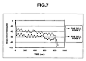
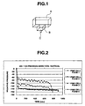
  • Figs. 2 to 7 show negative-pressure characteristics in the cases where the ultra fine cell foams shown in Table 1 were pressed in various manners.
  • the negative pressure was built up and was stable, with the use of a small amount of foam.
  • an ideal negative-pressure characteristic is obtained.
  • the amount of ink contained in the ink cartridge can be increased. Furthermore, by changing the material, it is possible to control the negative pressure.
Landscapes

  • Ink Jet (AREA)

Abstract

An ink feeding member comprising an ink tank for storing an ink, and an ink discharge control material placed in the ink tank to close an ink discharge port of the ink tank and to partially fill the ink tank, characterized in that the ink discharge control material is comprised of an ultra fine cell foam or a hot press formed product thereof with a density of 0.06 g/cm<3> or more, quantity of cells of 100/in or more, and a ventilation volume of 0.002 to 40 cc/cm<2>/sec.

Description

TECHNICAL FIELD
The present invention relates to an ink feeding member which is used, particularly, for feeding an ink to a printing head.
BACKGROUND ART
In recent years, there has been a remarkable progress in OA apparatuses, and, with respect to printers, there has been occurring a shift from the wire dot system and thermal transfer system to the ink jet system.
In the ink jet system, it is a common practice to contain an ink holding member in an ink tank (ink containing vessel) in order to hold an ink uniformly in the tank.
As the ink holding member, a polyurethane foam or a hot press formed product thereof is used. Conventionally, it has been practiced to pack the ink holding member densely into the tank and hold the ink in the cells of the ink holding member (a polyurethane foam or a hot press formed product thereof).
Hitherto, however, the urethane foam comparable in size to the ink tank (ink cartridge) has thus been used and, therefore, it has been difficult to increase the amount of ink contained in the tank and to reduce the amount of ink remaining in the tank after use.
Besides, the build-up of a negative pressure has been slow, and it has taken time until the jetting of the ink is stabilized.
DISCLOSURE OF INVENTION
Accordingly, it is an object of the present invention to provide an ink feeding member which makes it possible to increase the amount of ink contained and lower the ink remaining factor, to increase the use efficiency of ink, to obtain a sharp build-up of a negative pressure and shorten the time until stable jetting of ink, and to jet the ink stably.
In order to attain the above object, according to the present invention, there is provided an ink feeding member comprising an ink tank for containing an ink, and an ink discharge control material placed in the ink tank to close an ink discharge port of the ink tank and to partially fill the ink tank, characterized in that the ink discharge control material is composed of an ultra fine cell foam or a hot press formed product thereof with a density of 0.06 g/cm3 or more, quantity of cells of 100/in or more, and a ventilation volume of 0.002 to 40 cc/cm2/sec.
The ink feeding member according to the present invention comprises the ink discharge control material formed of the ultra fine cell foam or a hot press formed product thereof, which is placed in the ink tank (ink cartridge) to close an ink discharge port of the ink tank and to partially fill the ink tank (ink cartridge). This ensures that, while utilizing the characteristic that a negative pressure is built up even where the ink fills a portion on the upper side of the ink discharge control material, the use of the control material at a portion of the interior of the ink cartridge makes it possible to increase the amount of ink contained and lower the ink remaining factor, and to enhance the use efficiency of ink.
In addition, since the build-up of the negative pressure is sharp and the stability of the negative pressure is high, it is possible to shorten the time necessary for stabilization of jetting of ink and to achieve stable jetting of ink. Therefore, the ink feeding member according to the present invention can be used preferably as an ink feeding member for use in an ink jet type printer.
BRIEF DESCRIPTION OF DRAWINGS
  • Fig. 1 is a perspective view of an ink cartridge used in Example and Comparative Example.
  • Fig. 2 is a graph showing negative-pressure characteristics in the case where a hot pressed product of fine cell foam with a pressing factor of 2 and the pressing direction being vertical was used.
  • Fig. 3 is a graph showing negative-pressure characteristics in the case where a hot pressed product of fine cell foam with a pressing factor of 2 and the pressing direction being lateral was used.
  • Fig. 4 is a graph showing negative-pressure characteristics in the case where a hot pressed product of fine cell foam with a pressing factor of 2.5 and the pressing direction being lateral was used.
  • Fig. 5 is a graph showing negative-pressure characteristics in the case where a hot pressed product of fine cell foam with a pressing factor of 3 and the pressing direction being vertical was used.
  • Fig. 6 is a graph showing negative-pressure characteristics in the case where a hot pressed product of fine cell foam with a pressing factor of 3 and the pressing direction being lateral was used.
  • Fig. 7 is a graph showing negative-pressure characteristics in the case where a hot pressed product of fine cell foam with a pressing factor of 3.5 and the pressing direction being lateral was used.
  • BEST MODE FOR CARRYING OUT THE INVENTION
    The ink feeding member according to the present invention comprises an ink tank and an ink discharge control material. In this case, as the ink tank, there can be used an ink cartridge used for an ink jet type printer, or the like.
    On the other hand, as the ink discharge control material, there is used an ultra fine cell foam or a hot press formed product thereof with a density of 0.06 g/cm3 or more, particularly 0.065 g/cm3 or more, preferably 0.15 g/cm3 or less, more preferably 0.12 g/cm3 or less, quantity of cells of 100/in or more, particularly 120/in or more, preferably 200/in or less, and a ventilation volume of 0.002 cc/cm2/sec or more, particularly 10 cc/cm2/sec or more and 40 cc/cm2/sec or less, particularly 37 cc/cm2/sec or less.
    If the density is too low, the foam has the problem that the negative pressure would not be built up. In this case, if the density is too high, the negative pressure is built up excessively, possibly making it difficult to press the foam. In addition, if the quantity of cells is too small, the negative pressure would not be built up. On the contrary, if the quantity of cells is too large, the negative pressure may be built up excessively. If the ventilation volume is too small, the ink would not be jetted uniformly. On the contrary, if the ventilation volume is too large, the negative pressure would not rise. Incidentally, the ventilation volume is a value measured according to JIS K 6400.
    In this case, as the ink discharge control material, a hot press formed product of the above-mentioned foam is preferably used. The press direction in pressing the foam may be the vertical direction (ink flow-out direction) or the side direction (the direction perpendicular to the ink flow-out direction), or may be both of these directions. Where the pressing direction is the vertical direction, the pressing factor is preferably 2 to 3, more preferably 2 to 2.5. Where the pressing direction is the lateral direction, the pressing factor is preferably 2 to 4, more preferably 2.5 to 3.5. Incidentally, the hot pressing can be carried out by the normal method.
    Here, as the foam, a soft polyurethane foam is preferably used, and a soft polyurethane foam free of cell films is more preferably used.
    The ultra fine cell foam can be produced by any of known methods by which such an ultra fine cells can be obtained.
    In the ink feeding member according to the present invention, the above-mentioned ink discharge control material is placed in the ink tank to close an ink discharge port of the tank and to partially fill the tank. In this case, the filling factor of the ink discharge control material in filling the ink tank is preferably 10 to 15%, more preferably 11 to 12%, based on the internal volume of the ink tank.
    EXAMPLE
    The present invention will be described in detail by showing Example and Comparative Example, it being to be understood that the present invention is not limited to the following Example.
    Example and Comparative Example
    Polyether-based polyurethane foams having densities, quantities of cells, and ventilation volumes as shown in Table 1 were prepared.
    Material Density (g/cm3) Ventilation volume (cc/cm2/sec) Quantity of cells (pieces/inch)
    Comparative Example foam 0.056 80.0 60
    Ultra fine cell foam 1 0.091 35.0 120
    Ultra fine cell foam 2 0.106 10.2 150
    Ultra fine cell foam 3 0.106 20.2 170
    Ultra fine cell foam 4 0.117 13.0 180
    Next, each of hot pressed foams measuring 10 t × 15 × 23 mm as shown in Table 2 was placed to fill a bottom portion (case lower portion B) of a case (case upper portion A: 23 t × 50 × 23 mm; case lower portion B: 10 t × 15 × 23 mm) shown in Fig. 1. In the figure, C denotes the ink discharge port. In the case of Comparative Example foam, the foam is placed to fill up the whole part of the case (namely, the case A and the case B). The filling with the foam was conducted as follows. First, the foam was immersed in 10% ethanol solution, the foam was pressed flat to remove air therefrom, and the 10% ethanol solution was poured into the case to fill up the case. Thereafter, the 10% ethanol solution was drawn off at a rate of 2.0 cc/min, and the negative pressure was measured at intervals of 30 sec. The results are shown in Table 2.
    Material Pressing factor Pressing direction Ink capacity (cc) Stabilization time of negative pressure (sec) Negative pressure (mmH2O)
    Comparative Example foam - - 24.0 150 -30 to -50
    Ultra fine cell foam 1 2.5 lateral 26.5 30 -40 to -60
    Ultra fine cell foam 2 3.5 lateral 26.5 30 -50 to -60
    Ultra fine cell foam 3 2.0 vertical 26.5 30 -60 to -80
    Ultra fine cell foam 4 2.5 lateral 26.5 30 -100 to -110
    Incidentally, Figs. 2 to 7 show negative-pressure characteristics in the cases where the ultra fine cell foams shown in Table 1 were pressed in various manners.
    According to the present invention, the negative pressure was built up and was stable, with the use of a small amount of foam. Thus, an ideal negative-pressure characteristic is obtained. In addition, the amount of ink contained in the ink cartridge can be increased. Furthermore, by changing the material, it is possible to control the negative pressure.

    Claims (5)

    1. An ink feeding member comprising an ink tank for storing an ink, and an ink discharge control material placed in said ink tank to close an ink discharge port of said ink tank and to partially fill said ink tank, characterized in that said ink discharge control material is comprised of an ultra fine cell foam or a hot press formed product thereof with a density of 0.06 g/cm3 or more, quantity of cells of 100/in or more, and a ventilation volume of 0.002 to 40 cc/cm2/sec.
    2. An ink feeding member as set forth in claim 1, wherein said ink discharge control member has a density of 0.06 to 0.15 g/cm3, quantity of cells of 100 to 200/in, and a ventilation volume of 0.002 to 40 cc/cm2/sec.
    3. An ink feeding member as set forth in claim 2, wherein said ink discharge control member has a density of 0.065 to 0.12 g/cm3, quantity of cells of 120 to 200/in, and a ventilation volume of 10 to 37 cc/cm2/sec.
    4. An ink feeding member as set forth in claim 1, 2 or 3, wherein said ultra fine cell foam is comprised of a soft polyurethane foam.
    5. An ink feeding member as set forth in any one of claims 1 to 4, wherein the filling factor of said ink discharge control material in filling said ink tank is 10 to 15% based on the internal volume of said ink tank.
    EP02775303A 2001-10-09 2002-10-08 Ink feeding member Withdrawn EP1440806A4 (en)

    Applications Claiming Priority (3)

    Application Number Priority Date Filing Date Title
    JP2001311318A JP2003112434A (en) 2001-10-09 2001-10-09 Ink supply member
    JP2001311318 2001-10-09
    PCT/JP2002/010441 WO2003031189A1 (en) 2001-10-09 2002-10-08 Ink feeding member

    Publications (2)

    Publication Number Publication Date
    EP1440806A1 true EP1440806A1 (en) 2004-07-28
    EP1440806A4 EP1440806A4 (en) 2006-04-12

    Family

    ID=19130172

    Family Applications (1)

    Application Number Title Priority Date Filing Date
    EP02775303A Withdrawn EP1440806A4 (en) 2001-10-09 2002-10-08 Ink feeding member

    Country Status (5)

    Country Link
    US (1) US20040196337A1 (en)
    EP (1) EP1440806A4 (en)
    JP (1) JP2003112434A (en)
    CN (1) CN1568258A (en)
    WO (1) WO2003031189A1 (en)

    Families Citing this family (1)

    * Cited by examiner, † Cited by third party
    Publication number Priority date Publication date Assignee Title
    CN101108555B (en) * 2006-07-21 2010-11-10 研能科技股份有限公司 Porous absorbing material and ink cartridge with porous absorbing material

    Family Cites Families (6)

    * Cited by examiner, † Cited by third party
    Publication number Priority date Publication date Assignee Title
    GB2249054B (en) * 1990-07-10 1994-10-19 Canon Kk Ink tank,ink jet cartridge having the tank,and ink jet recording apparatus having the cartridge
    JP2960235B2 (en) * 1991-11-12 1999-10-06 キヤノン株式会社 INK CONTAINER, PRINT HEAD UNIT USING THE SAME, AND PRINTING APPARATUS MOUNTING THE SAME
    US5587731A (en) * 1994-02-22 1996-12-24 Bridgestone Corporation Ink retainer
    JP2000141684A (en) * 1998-11-12 2000-05-23 Seiko Instruments Inc Ink cartridge
    JP2001105622A (en) * 1999-08-03 2001-04-17 Bridgestone Corp Ink holder
    JP2001105630A (en) * 1999-08-03 2001-04-17 Bridgestone Corp Ink waste liquid absorber and production thereof

    Also Published As

    Publication number Publication date
    JP2003112434A (en) 2003-04-15
    CN1568258A (en) 2005-01-19
    EP1440806A4 (en) 2006-04-12
    US20040196337A1 (en) 2004-10-07
    WO2003031189A1 (en) 2003-04-17

    Similar Documents

    Publication Publication Date Title
    EP1808295B1 (en) Ink container with dual negative pressure producing members urged together and method of manufacturing the same
    EP0845362B1 (en) Container for liquid to be ejected
    US6145974A (en) Ink-supplied printer head and ink container
    EP0577439B1 (en) Ink tank
    EP0493058A2 (en) Method and apparatus for supplying ink to an ink jet printer
    GB2293142A (en) Capillary regulation of ink flow in multi-chambered ink cartridge for ink jet printer.
    US7014306B2 (en) Liquid reservoir apparatus
    US6276785B1 (en) Ink-supplied printer head and ink container
    US6471346B2 (en) Liquid container for ink jet head
    EP1440806A1 (en) Ink feeding member
    US6474798B1 (en) Ink supplied printer head and ink container
    MXPA02006969A (en) Ink retaining foams.
    EP0709210B1 (en) Ink-jet pen with capillarity gradient
    JPH0890783A (en) Ink tank and ink jet printing apparatus using the ink tank
    JP3728053B2 (en) Liquid container for discharge
    JP3244806B2 (en) Inkjet cartridge
    EP1095779A2 (en) Method and apparatus for refilling an ink container
    CN219486938U (en) Ink cartridge
    JP3281285B2 (en) Liquid container
    JP2006044214A (en) Liquid storage container
    JPH0615840A (en) Ink holding member
    US5900897A (en) Ink cartridge
    JP2005199496A (en) Ink pack, ink cartridge, and ink supply device
    JPH07125239A (en) INK TANK UNIT, INKJET CARTRIDGE HAVING THE INK TANK UNIT, AND INKJET DEVICE HAVING THE INKJET CARTRIDGE
    CN101374667A (en) ink cartridge

    Legal Events

    Date Code Title Description
    PUAI Public reference made under article 153(3) epc to a published international application that has entered the european phase

    Free format text: ORIGINAL CODE: 0009012

    17P Request for examination filed

    Effective date: 20040408

    AK Designated contracting states

    Kind code of ref document: A1

    Designated state(s): AT BE BG CH CY CZ DE DK EE ES FI FR GB GR IE IT LI LU MC NL PT SE SK TR

    AX Request for extension of the european patent

    Extension state: AL LT LV MK RO SI

    A4 Supplementary search report drawn up and despatched

    Effective date: 20060224

    REG Reference to a national code

    Ref country code: DE

    Ref legal event code: 8566

    STAA Information on the status of an ep patent application or granted ep patent

    Free format text: STATUS: THE APPLICATION HAS BEEN WITHDRAWN

    18W Application withdrawn

    Effective date: 20060925