EP1440757A2 - Corrugated fin cutting device and cutting method - Google Patents
Corrugated fin cutting device and cutting method Download PDFInfo
- Publication number
- EP1440757A2 EP1440757A2 EP04290207A EP04290207A EP1440757A2 EP 1440757 A2 EP1440757 A2 EP 1440757A2 EP 04290207 A EP04290207 A EP 04290207A EP 04290207 A EP04290207 A EP 04290207A EP 1440757 A2 EP1440757 A2 EP 1440757A2
- Authority
- EP
- European Patent Office
- Prior art keywords
- fin material
- bottom portion
- cutting
- guide piece
- fin
- Prior art date
- Legal status (The legal status is an assumption and is not a legal conclusion. Google has not performed a legal analysis and makes no representation as to the accuracy of the status listed.)
- Granted
Links
Images



Classifications
-
- B—PERFORMING OPERATIONS; TRANSPORTING
- B23—MACHINE TOOLS; METAL-WORKING NOT OTHERWISE PROVIDED FOR
- B23D—PLANING; SLOTTING; SHEARING; BROACHING; SAWING; FILING; SCRAPING; LIKE OPERATIONS FOR WORKING METAL BY REMOVING MATERIAL, NOT OTHERWISE PROVIDED FOR
- B23D33/00—Accessories for shearing machines or shearing devices
- B23D33/10—Stops for positioning work
-
- B—PERFORMING OPERATIONS; TRANSPORTING
- B23—MACHINE TOOLS; METAL-WORKING NOT OTHERWISE PROVIDED FOR
- B23D—PLANING; SLOTTING; SHEARING; BROACHING; SAWING; FILING; SCRAPING; LIKE OPERATIONS FOR WORKING METAL BY REMOVING MATERIAL, NOT OTHERWISE PROVIDED FOR
- B23D33/00—Accessories for shearing machines or shearing devices
- B23D33/02—Arrangements for holding, guiding, and/or feeding work during the operation
-
- Y—GENERAL TAGGING OF NEW TECHNOLOGICAL DEVELOPMENTS; GENERAL TAGGING OF CROSS-SECTIONAL TECHNOLOGIES SPANNING OVER SEVERAL SECTIONS OF THE IPC; TECHNICAL SUBJECTS COVERED BY FORMER USPC CROSS-REFERENCE ART COLLECTIONS [XRACs] AND DIGESTS
- Y10—TECHNICAL SUBJECTS COVERED BY FORMER USPC
- Y10T—TECHNICAL SUBJECTS COVERED BY FORMER US CLASSIFICATION
- Y10T83/00—Cutting
- Y10T83/04—Processes
- Y10T83/0605—Cut advances across work surface
-
- Y—GENERAL TAGGING OF NEW TECHNOLOGICAL DEVELOPMENTS; GENERAL TAGGING OF CROSS-SECTIONAL TECHNOLOGIES SPANNING OVER SEVERAL SECTIONS OF THE IPC; TECHNICAL SUBJECTS COVERED BY FORMER USPC CROSS-REFERENCE ART COLLECTIONS [XRACs] AND DIGESTS
- Y10—TECHNICAL SUBJECTS COVERED BY FORMER USPC
- Y10T—TECHNICAL SUBJECTS COVERED BY FORMER US CLASSIFICATION
- Y10T83/00—Cutting
- Y10T83/465—Cutting motion of tool has component in direction of moving work
- Y10T83/4757—Tool carrier shuttles rectilinearly parallel to direction of work feed
-
- Y—GENERAL TAGGING OF NEW TECHNOLOGICAL DEVELOPMENTS; GENERAL TAGGING OF CROSS-SECTIONAL TECHNOLOGIES SPANNING OVER SEVERAL SECTIONS OF THE IPC; TECHNICAL SUBJECTS COVERED BY FORMER USPC CROSS-REFERENCE ART COLLECTIONS [XRACs] AND DIGESTS
- Y10—TECHNICAL SUBJECTS COVERED BY FORMER USPC
- Y10T—TECHNICAL SUBJECTS COVERED BY FORMER US CLASSIFICATION
- Y10T83/00—Cutting
- Y10T83/647—With means to convey work relative to tool station
- Y10T83/6656—Rectilinear movement only
- Y10T83/6657—Tool opposing pusher
- Y10T83/666—Screw actuated
-
- Y—GENERAL TAGGING OF NEW TECHNOLOGICAL DEVELOPMENTS; GENERAL TAGGING OF CROSS-SECTIONAL TECHNOLOGIES SPANNING OVER SEVERAL SECTIONS OF THE IPC; TECHNICAL SUBJECTS COVERED BY FORMER USPC CROSS-REFERENCE ART COLLECTIONS [XRACs] AND DIGESTS
- Y10—TECHNICAL SUBJECTS COVERED BY FORMER USPC
- Y10T—TECHNICAL SUBJECTS COVERED BY FORMER US CLASSIFICATION
- Y10T83/00—Cutting
- Y10T83/727—With means to guide moving work
-
- Y—GENERAL TAGGING OF NEW TECHNOLOGICAL DEVELOPMENTS; GENERAL TAGGING OF CROSS-SECTIONAL TECHNOLOGIES SPANNING OVER SEVERAL SECTIONS OF THE IPC; TECHNICAL SUBJECTS COVERED BY FORMER USPC CROSS-REFERENCE ART COLLECTIONS [XRACs] AND DIGESTS
- Y10—TECHNICAL SUBJECTS COVERED BY FORMER USPC
- Y10T—TECHNICAL SUBJECTS COVERED BY FORMER US CLASSIFICATION
- Y10T83/00—Cutting
- Y10T83/869—Means to drive or to guide tool
- Y10T83/8878—Guide
Definitions
- the present invention relates to a corrugated fin cutting device and cutting method for cutting a corrugated fin material, which is continuously conveyed, to obtain a corrugated fin.
- a conventional corrugated fin cutting device is disclosed in Japanese Patent Laid-open No. Tokkaihei 5-23912.
- This corrugated fin cutting device utilizes counting worms constituted of a pair of worms twisted in the right and left directions engaging respectively with both shoulder portions of corrugated fin material and conveying the fin material in a conveying direction while counting the number of ridges of the fin material.
- corrugated fin cutting device is disclosed in Japanese Patent Laid-open No. Tokkai 2002-109509.
- the aforementioned both worms convey the fin material by a predetermined number of ridges and then stops it, and movable cutting blades mounted on the tips of the both worms are quickly brought down to cut the fin material, to thereby obtain a corrugated fin having a predetermined length.
- end portions of the corrugated fins becomes irregular when they are assembled with a core to cause an appearance defect, or to cause a defect on a joint condition between a sheet plate of a radiator or the like and a tube.
- the present invention is made in view of the above-mentioned problems, and an object thereof is to provide a corrugated fin cutting device and cutting method that realize high product precision and improvement in productivity of corrugated fins by surely cutting the fin material at a predetermined position without stopping the fin material that is continuously conveyed or without causing the fin material to be damaged or twisted by the worms.
- a corrugated fin cutting device comprises: a position restraining unit that restrains a position of a bottom portion of a corrugated fin material that is being continuously conveyed in a conveying direction; a position determining unit that approaches the bottom portion of the fin material to determine a position and moves in the conveying direction in synchronization with the fin material that is being conveyed; and a cutting unit that moves with the position determining unit in the conveying direction and cuts the bottom portion of the fin material at the position determined by the position determining unit.
- the position restraining unit restrains the position of the bottom portion of the corrugated fin material that is being continuously conveyed in the conveying direction, and the position determining unit approaches the bottom portion of the fin material to determine a cutting position of the fin material and moves in the conveying direction in synchronization with the fin material.
- the cutting unit cuts the bottom portion of the fin material at the position determined by the position determining unit, to thereby obtain a corrugated fin having a predetermined length.
- the fin material can be surely cut at the predetermined position without stopping the fin material that is being continuously conveyed, which prevents the fin material from expanding and contracting, so that the high product precision and improvement in productivity of the corrugated fin can be realized.
- the position restraining unit is a pair of worms that engages respectively with both shoulder portions of the corrugated fin material and continuously conveys the fin material in the conveying direction
- the position determining unit is a guide piece that approaches the bottom portion of the fin material that is being engaged with the both worms to determine a position and moves in the conveying direction in synchronization with the fin material that is being conveyed
- the cutting unit has cutting blades that move with the guide piece in the conveying direction of the fin material and cut the bottom portion of the fin material that is guided by the guide piece when the guide piece passes the both worms.
- the pair of worms engages respectively with both the shoulder portions of the fin material and continuously conveys the fin material in the conveying direction.
- the guide piece When the fin material is conveyed by the predetermined number of bottom portions, the guide piece approaches the bottom portion of the fin material engaged with the both worms to determine a cutting position of the bottom portion, and the guide piece and the cutting blades move in the conveying direction in synchronization with the fin material.
- the cutting blades cut the fin material at the bottom portion of the fin material that is guided by the guide piece to obtain the corrugated fin having a predetermined length.
- the guide piece surely approaches the bottom portion of the fin material, which is adjusted by the both worms engaging with the both shoulder portions, so that the cutting position of the fin material can be easily determined.
- the guide piece and the cutting blades move in the conveying direction in synchronization with the fin material and cut the fin material during the movement, it is not necessary to stop the fin material as needed in a conventional corrugated fin cutting device, which prevents the fin material from expanding and contracting, so that the high product precision and improvement in productivity of the corrugated fin can be realized.
- a corrugated fin cutting method comprises: a position restraining step of restraining by a position restraining unit a position of a bottom portion of a corrugated fin material that is being continuously conveyed in a conveying direction; a position determining step of determining a position of the bottom portion of the restrained fin material by a guide piece approaching the bottom portion, and then moving the guide piece in synchronizing with the fin material in the conveying direction; and a cutting step of moving cutting blades with the guide piece in the conveying direction, and cutting by the cutting unit the bottom portion of the fin material at the position determined by the guide piece.
- the position restraining step the position of the bottom portion of the corrugated fin material that is being continuously conveyed in the conveying direction is restrained, and in the position determining step, the guide piece approaches the bottom portion of the restrained fin material to determine the position of the bottom portion, and the guide piece is moved in the conveyed direction in synchronization with the fin material.
- the cutting unit is moved with the guide piece in the conveying direction, and cuts the bottom portion of the fin material at the position determined by the guide piece.
- the guide piece and the cutting unit move in the conveying direction in synchronization with the corrugated fin material that is continuously conveyed in the conveying direction, and the cutting unit cuts the bottom portion of the fin material that is guided by the guide piece during the movement, the corrugated fin having a predetermined length can be obtained without stopping the conveyance of the fin material as needed in the conventional invention.
- the cutting unit cuts the bottom portion of the fin material after the guide piece passes the position restraining unit.
- the cutting unit cuts the bottom portion of the fin material after the guide piece passes the position restraining unit in the cutting step, it is possible to assure the size of engagement with the fin material by which the position restraining unit can surely restrain the position of the fin material, and at the time of cutting, the cutting blades can surely cut the bottom portion of the fin material without interfering the position restraining unit.
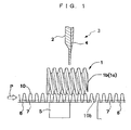
- FIG. 1 is a side view of the corrugated fin cutting device according to the embodiment of the present invention
- FIG. 2 is a plan view showing a positional relationship between worms and fin material in the corrugated fin cutting device according to this embodiment
- FIG. 3 is a perspective view of movable cutting blades and its guide
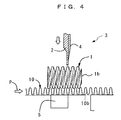
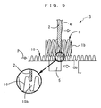
- FIG. 4 to FIG. 6 are views respectively describing operation of the corrugated fin cutting device along a line S4 to S4 in FIG. 2.
- the corrugated fin cutting device mainly constituted by a pair of worms 1 that convey a corrugated fin material 10 made of a metal sheet and determine a position of a bottom portion 10b of the fin material 10, a guide piece 2, and movable cutting blades 3 that cut the fin material 10 at a position of the guide piece 2.
- the worms 1, the guide piece 2, and the cutting blades 3 function as a position restraining unit of the present invention, a positioning unit of the present invention, and a cutting unit of the present invention respectively.
- the worms 1 continuously convey the fin material 10 on a conveying table 6 in a conveying direction, which is the direction of an arrow P in FIG. 1, by rotating of the worms in rotational directions opposite to each other, which are the rotational directions shown by arrows Sa and Sb in FIG. 2.
- the worms 1 are constituted by a worm 1a with right-hand teeth and a worm 1b with left-hand teeth that restrain the position of the bottom portion of the fin material 10 while conveying the fin material 10.
- the both of these worms 1a and 1b engage respectively with both shoulder portions 10a of the fin material 10, which are set to have the same pitch as that of a corrugated fin to be manufactured, in order to restrain the position of the bottom portion 10b of fin material 10.
- worms 1a and 1b are coupled by a gear, not shown and is driven by a servomotor, not shown to rotate respectively.
- a control unit, not shown can count the number of bottom portions 10b of the conveyed fin material 10 from the number of rotation of at least one of these worms 1a and 1b.
- the guide piece 2 is for guiding a movable cutting blade 4 arranged above the fin material 10 to a cutting position of the fin material 10, and its downside portion is formed in curves to avoid the both worms 1a and 1b, and a tip thereof is formed to have a thickness and a width capable of approaching the bottom portion 10b of the fin material 10 between the worm 1a and the worm 1b.
- the cutting blades 3 are, as shown in FIG. 1, constituted by the movable cutting blade 4 arranged above the fin material 10 and a fixed cutting blade 5 arranged below the fin material 10 at a position corresponding to that of the movable cutting blade 4.
- the movable cutting blade 4 is used for cutting the fin material 10 by moving down along the guide piece 2, and has, as shown in FIG. 3, a blade portion 4a that is formed on its downside and reinforcing portions 4b and 4b that are formed thicker than the blade portion 4a and arranged at the both sides of the blade portion 4a.
- the guide piece 2 and the cutting blades 3 are mounted on a traveling carriage, not shown, and provided on the conveying table 6 to be movable in a conveying direction of the fin material 10 by a cam, not shown linked to the traveling carriage, and is controlled to be movable in synchronization with the fin material 10 conveyed according to the rotations of the both worms 1a and 1b.
- fin guides 7 that guide the both sides of the fin material 10 are provided.
- the fin material 10 is supplied and conveyed on the conveying table 6 by the worms 1, and then in a position restraining step, as shown in FIG. 4, the worms 1 engage with the bottom portion 10b of the fin material 10 and restrain the position of the engaged bottom portion 10b. Further, at this time, the control unit counts the number of bottom portions 10b of the fin material 10 from the rotation of the worms 1.
- a position determining step as shown in FIG. 5, when the fin material 10 is conveyed by the predetermined number of bottom portions 10b by the worms 1 and then a position of the bottom portion 10b to be cut is determined, the guide piece 2 approaches the determined position of the bottom portion 10b of the fin material 10 that is engaged with the worms 1. This approach is made while the fin material 10 is conveying without being stopped.
- the control unit When the position determination by the guide piece 2 is completed, the control unit resets the counted number of ridges of the worms 1, and starts new counting from a bottom portion that is more upstream side by one from the bottom portion 10b.
- the guide piece 2 that has approached the bottom portion 10b of the fin material 10 moves in the conveying direction in synchronization with the fin material 10.
- the cutting blades 3 move with the guide piece 2 in the conveying direction.
- the guide piece 2, the movable cutting blade 4, and the fixed cutting blade 5 return to their original positions and then wait until the fin material 10 is conveyed again by the worms 1 by the predetermined number of ridges. Incidentally, during all of these steps, the fin material 10 is continuously conveyed without being stopped.
- the guide piece 2 approaches the cutting position of the fin material 10, and this guide piece 2 moves in the conveying direction with the cutting blades 3 in synchronization with the fin material 10. During this movement, the cutting blades 3 cut the fin material at the cutting position. Therefore, as compared to the conventional corrugated fin cutting device, the fin material 10 is cut at a predetermined position without stopping the conveyance of the fin material 10, so that the corrugated fin 11 having a predetermined length can be obtained in a short period of time, thereby contributing to the improvement in productivity of the corrugated fin.
- the fin material does not expand or contract to heavily contact the worms 1 by being stopped in the middle similarly to the conventional corrugated fin cutting device, so that a fin material in a desired form can be formed stably.
- the corrugated fin 11 having high product precision can be obtained.
- the bottom portion 10b of the fin material 10 is counted by the worms 1 as a timing for the guide piece 2 to approach the bottom portion 10b of the fin material 10, but the guide piece 2 may be inserted by an interval of predetermined unit time.
- the moving ranges for moving the guide piece 2 and the cutting blades 3 in synchronization with the fin material 10 can be set according to each case.
- the cutting unit may be constructed so that it moves at first independently from the guide peace 2, not moving together with the guide piece 2, to the guide peace 2 and then move with the guide peace 2 while cutting the bottom portion 10b, determined by the guide peace 2, of fin material 10.
Landscapes
- Engineering & Computer Science (AREA)
- Mechanical Engineering (AREA)
- Shearing Machines (AREA)
- Details Of Cutting Devices (AREA)
Abstract
Description
Claims (4)
- A corrugated fin cutting device, comprising:a position restraining unit (1) that restrains a position of a bottom portion (10b) of a corrugated fin material (10) that is being continuously conveyed in a conveying direction;a position determining unit (2) that approaches the bottom portion (10b) of the fin material (10) to determine a position and moves in the conveying direction in synchronization with the fin material (10) that is being conveyed; anda cutting unit (3) that moves with said position determining unit (2) in the conveying direction and cuts the bottom portion (10b) of the fin material (10) at the position determined by said position determining unit (2).
- The corrugated fin cutting device according to claim 1,
wherein said position restraining unit (1) is a pair of worms (1) that engages respectively with both shoulder portions (10a) of the corrugated fin material (10) and continuously conveys the fin material (10) in the conveying direction,
wherein said position determining unit (2) is a guide piece (2) that approaches the bottom portion (10b) of the fin material (10) that is being engaged with said both worms (1) to determine a position and moves in the conveying direction in synchronization with the fin material (10) that is being conveyed; and
wherein said cutting unit (3) has cutting blades (4, 5) that moves with said position determining unit (2) in the conveying direction of the fin material (10) and cut the bottom portion (10b) of the fin material (10) that is being guided by said guide piece (2) when said guide piece (2) passes said both worms (1). - A corrugated fin cutting method, comprising the steps of :restraining a position of a bottom portion (10b) of a corrugated fin material (10) that is being continuously conveyed in a conveying direction;approaching said bottom portion (10b) by a guide piece (2), and then moving the guide piece (2) in synchronizing with the fin material (10) in the conveying direction;moving a cutting unit (3) with said guide piece (2) in the conveying direction; andcutting the bottom portion (10b) of the fin material (10) by the cutting unit (3), at a position determined by the guide piece (2).
- A corrugated fin cutting method according to claim 3:
wherein the bottom portion (10b) of the fin material (10) is cut after the guide piece (2) passes a position of a restraining unit used for restraining the position of the bottom portion (10b).
Applications Claiming Priority (2)
| Application Number | Priority Date | Filing Date | Title |
|---|---|---|---|
| JP2003017356A JP4108492B2 (en) | 2003-01-27 | 2003-01-27 | Corrugated fin cutting device |
| JP2003017356 | 2003-01-27 |
Publications (3)
| Publication Number | Publication Date |
|---|---|
| EP1440757A2 true EP1440757A2 (en) | 2004-07-28 |
| EP1440757A3 EP1440757A3 (en) | 2005-05-18 |
| EP1440757B1 EP1440757B1 (en) | 2006-08-30 |
Family
ID=32588707
Family Applications (1)
| Application Number | Title | Priority Date | Filing Date |
|---|---|---|---|
| EP20040290207 Expired - Lifetime EP1440757B1 (en) | 2003-01-27 | 2004-01-27 | Corrugated fin cutting device and cutting method |
Country Status (4)
| Country | Link |
|---|---|
| US (1) | US7032487B2 (en) |
| EP (1) | EP1440757B1 (en) |
| JP (1) | JP4108492B2 (en) |
| DE (1) | DE602004002118T2 (en) |
Families Citing this family (9)
| Publication number | Priority date | Publication date | Assignee | Title |
|---|---|---|---|---|
| JP4929370B2 (en) * | 2010-03-25 | 2012-05-09 | 日高精機株式会社 | Corrugated fin cutting device |
| PL2841240T3 (en) | 2012-04-23 | 2017-12-29 | Urschel Laboratories, Inc. | A device for cutting food products |
| CN107855586A (en) * | 2017-07-04 | 2018-03-30 | 洪恒丰 | A kind of easy-to-use pipeline fixing device |
| CN111408797B (en) * | 2020-04-26 | 2024-09-13 | 广州市奇虎实业有限公司 | A processing device and a processing method for heat dissipation fins |
| USD969570S1 (en) | 2021-03-29 | 2022-11-15 | Urschel Laboratories, Inc. | Knife |
| USD969449S1 (en) | 2021-03-29 | 2022-11-15 | Urschel Laboratories, Inc. | Food product |
| USD979178S1 (en) | 2021-03-29 | 2023-02-28 | Urschel Laboratories, Inc. | Food product |
| CN116140703B (en) * | 2022-09-16 | 2026-06-02 | 金龙精密铜管集团股份有限公司 | A precision copper tube cutting device with outer fins |
| CN116275268B (en) * | 2023-04-11 | 2023-10-27 | 江苏久泰智能科技有限公司 | Corrugated pipe cutting device |
Family Cites Families (14)
| Publication number | Priority date | Publication date | Assignee | Title |
|---|---|---|---|---|
| US2509760A (en) * | 1946-05-15 | 1950-05-30 | Robertson Co H H | Shearing apparatus |
| US4262568A (en) * | 1979-11-08 | 1981-04-21 | Wallis Bernard J | Cut-off mechanism for corrugated strip |
| GB2118881B (en) * | 1982-04-14 | 1986-02-12 | Nippon Denso Co | Method and apparatus for cutting continuous corrugated member |
| US4480456A (en) * | 1982-07-08 | 1984-11-06 | Nippondenso Co., Ltd. | Method and apparatus for cutting continuous corrugated members |
| US4507948A (en) * | 1983-11-04 | 1985-04-02 | Wallis Bernard J | Method and apparatus for cutting corrugated strip |
| US5138861A (en) * | 1989-06-05 | 1992-08-18 | Wallis Bernard J | Method and apparatus for cutting corrugated webs |
| JP2989292B2 (en) | 1991-03-15 | 1999-12-13 | 三菱重工業株式会社 | Cutting method of corrugated fin |
| JP3019273B2 (en) | 1991-07-18 | 2000-03-13 | カルソニック株式会社 | Corrugated fin cutting equipment |
| US5207083A (en) * | 1991-12-06 | 1993-05-04 | General Motors Corporation | Method of controlling the length of corrugated fins |
| JPH10309620A (en) | 1997-05-07 | 1998-11-24 | Calsonic Corp | Corrugated fin cutting device |
| JPH10309621A (en) | 1997-05-07 | 1998-11-24 | Calsonic Corp | Corrugated fin cutting device |
| JP3661518B2 (en) | 1999-09-09 | 2005-06-15 | 株式会社デンソー | Continuous wave cutting device |
| EP1103316B1 (en) * | 1999-11-26 | 2006-05-17 | Calsonic Kansei Corporation | Method for manufacturing corrugated fin |
| JP2002109509A (en) | 2000-10-04 | 2002-04-12 | Hitachi Medical Corp | Medical image diagnostic equipment |
-
2003
- 2003-01-27 JP JP2003017356A patent/JP4108492B2/en not_active Expired - Fee Related
-
2004
- 2004-01-26 US US10/763,167 patent/US7032487B2/en not_active Expired - Fee Related
- 2004-01-27 DE DE200460002118 patent/DE602004002118T2/en not_active Expired - Fee Related
- 2004-01-27 EP EP20040290207 patent/EP1440757B1/en not_active Expired - Lifetime
Also Published As
| Publication number | Publication date |
|---|---|
| US20040149102A1 (en) | 2004-08-05 |
| DE602004002118T2 (en) | 2007-04-19 |
| JP2004223685A (en) | 2004-08-12 |
| EP1440757A3 (en) | 2005-05-18 |
| US7032487B2 (en) | 2006-04-25 |
| DE602004002118D1 (en) | 2006-10-12 |
| JP4108492B2 (en) | 2008-06-25 |
| EP1440757B1 (en) | 2006-08-30 |
Similar Documents
| Publication | Publication Date | Title |
|---|---|---|
| EP1440757B1 (en) | Corrugated fin cutting device and cutting method | |
| US6487887B2 (en) | Working apparatus and method for band blade | |
| CN107005134A (en) | Coil formers and coils for rotating electric machines | |
| EP2599566B1 (en) | Apparatus for manufacturing coil spring | |
| US4956987A (en) | Rotary cutter for cutting a continuous corrugated strip | |
| JP6623308B2 (en) | Production equipment for heat exchanger fins | |
| JP3659362B2 (en) | Temporary assembly device for heat exchanger core | |
| CN109415178B (en) | Device for conveying fin forming body for heat exchanger | |
| CN109985962A (en) | Automatic rule bender and its mobile device | |
| JP7109997B2 (en) | Cutting device | |
| KR101828842B1 (en) | Cutting device | |
| WO2002070164A1 (en) | Device for cutting metal strips to length | |
| CN112974578A (en) | High-speed full-automatic bending belt production equipment | |
| JP2008168368A (en) | Cutting method for corrugated fin and cutting device thereof | |
| CN116673546A (en) | Automatic cutting-off forming machine | |
| CN105828999B (en) | Fin manufacture device | |
| US20060112540A1 (en) | Corrugated fin feeding apparatus and feeding method | |
| JP4374311B2 (en) | Sheet metal positioning mechanism | |
| CN109415179B (en) | Device for transporting a finned shaped body for flat tubes | |
| JP2001079711A (en) | Continuous wavy body cutting device | |
| JP2016175097A (en) | Processing apparatus and processing method for metal thin plate | |
| EP1123767B1 (en) | Corrugation cut-off apparatus | |
| JP2008062314A (en) | Method and device for cutting corrugated fin | |
| SU1494147A1 (en) | Device for manufacture slot insulation boxes | |
| CN112108592A (en) | A roll over and cut device and roll over PIN machine for rolling over PIN machine |
Legal Events
| Date | Code | Title | Description |
|---|---|---|---|
| PUAI | Public reference made under article 153(3) epc to a published international application that has entered the european phase |
Free format text: ORIGINAL CODE: 0009012 |
|
| AK | Designated contracting states |
Kind code of ref document: A2 Designated state(s): AT BE BG CH CY CZ DE DK EE ES FI FR GB GR HU IE IT LI LU MC NL PT RO SE SI SK TR |
|
| AX | Request for extension of the european patent |
Extension state: AL LT LV MK |
|
| PUAL | Search report despatched |
Free format text: ORIGINAL CODE: 0009013 |
|
| AK | Designated contracting states |
Kind code of ref document: A3 Designated state(s): AT BE BG CH CY CZ DE DK EE ES FI FR GB GR HU IE IT LI LU MC NL PT RO SE SI SK TR |
|
| AX | Request for extension of the european patent |
Extension state: AL LT LV MK |
|
| RIC1 | Information provided on ipc code assigned before grant |
Ipc: 7B 23D 33/02 A Ipc: 7B 21D 43/28 B Ipc: 7B 23D 25/04 B Ipc: 7B 23D 33/10 B |
|
| 17P | Request for examination filed |
Effective date: 20050707 |
|
| AKX | Designation fees paid |
Designated state(s): DE FR GB |
|
| GRAP | Despatch of communication of intention to grant a patent |
Free format text: ORIGINAL CODE: EPIDOSNIGR1 |
|
| GRAS | Grant fee paid |
Free format text: ORIGINAL CODE: EPIDOSNIGR3 |
|
| GRAA | (expected) grant |
Free format text: ORIGINAL CODE: 0009210 |
|
| AK | Designated contracting states |
Kind code of ref document: B1 Designated state(s): DE FR GB |
|
| REG | Reference to a national code |
Ref country code: GB Ref legal event code: FG4D |
|
| REF | Corresponds to: |
Ref document number: 602004002118 Country of ref document: DE Date of ref document: 20061012 Kind code of ref document: P |
|
| ET | Fr: translation filed | ||
| PLBE | No opposition filed within time limit |
Free format text: ORIGINAL CODE: 0009261 |
|
| STAA | Information on the status of an ep patent application or granted ep patent |
Free format text: STATUS: NO OPPOSITION FILED WITHIN TIME LIMIT |
|
| 26N | No opposition filed |
Effective date: 20070531 |
|
| PGFP | Annual fee paid to national office [announced via postgrant information from national office to epo] |
Ref country code: DE Payment date: 20090123 Year of fee payment: 6 |
|
| PGFP | Annual fee paid to national office [announced via postgrant information from national office to epo] |
Ref country code: GB Payment date: 20090121 Year of fee payment: 6 |
|
| REG | Reference to a national code |
Ref country code: GB Ref legal event code: 746 Effective date: 20090924 |
|
| PGFP | Annual fee paid to national office [announced via postgrant information from national office to epo] |
Ref country code: FR Payment date: 20100208 Year of fee payment: 7 |
|
| GBPC | Gb: european patent ceased through non-payment of renewal fee |
Effective date: 20100127 |
|
| PG25 | Lapsed in a contracting state [announced via postgrant information from national office to epo] |
Ref country code: DE Free format text: LAPSE BECAUSE OF NON-PAYMENT OF DUE FEES Effective date: 20100803 |
|
| PG25 | Lapsed in a contracting state [announced via postgrant information from national office to epo] |
Ref country code: GB Free format text: LAPSE BECAUSE OF NON-PAYMENT OF DUE FEES Effective date: 20100127 |
|
| REG | Reference to a national code |
Ref country code: FR Ref legal event code: ST Effective date: 20110930 |
|
| PG25 | Lapsed in a contracting state [announced via postgrant information from national office to epo] |
Ref country code: FR Free format text: LAPSE BECAUSE OF NON-PAYMENT OF DUE FEES Effective date: 20110131 |