EP1440720A2 - Strainer - Google Patents
Strainer Download PDFInfo
- Publication number
- EP1440720A2 EP1440720A2 EP04250375A EP04250375A EP1440720A2 EP 1440720 A2 EP1440720 A2 EP 1440720A2 EP 04250375 A EP04250375 A EP 04250375A EP 04250375 A EP04250375 A EP 04250375A EP 1440720 A2 EP1440720 A2 EP 1440720A2
- Authority
- EP
- European Patent Office
- Prior art keywords
- conduit
- strainer
- downstream
- upstream
- sleeve
- Prior art date
- Legal status (The legal status is an assumption and is not a legal conclusion. Google has not performed a legal analysis and makes no representation as to the accuracy of the status listed.)
- Granted
Links
Images


Classifications
-
- B—PERFORMING OPERATIONS; TRANSPORTING
- B01—PHYSICAL OR CHEMICAL PROCESSES OR APPARATUS IN GENERAL
- B01D—SEPARATION
- B01D35/00—Filtering devices having features not specifically covered by groups B01D24/00 - B01D33/00, or for applications not specifically covered by groups B01D24/00 - B01D33/00; Auxiliary devices for filtration; Filter housing constructions
- B01D35/02—Filters adapted for location in special places, e.g. pipe-lines, pumps, stop-cocks
-
- B—PERFORMING OPERATIONS; TRANSPORTING
- B01—PHYSICAL OR CHEMICAL PROCESSES OR APPARATUS IN GENERAL
- B01D—SEPARATION
- B01D29/00—Filters with filtering elements stationary during filtration, e.g. pressure or suction filters, not covered by groups B01D24/00 - B01D27/00; Filtering elements therefor
- B01D29/11—Filters with filtering elements stationary during filtration, e.g. pressure or suction filters, not covered by groups B01D24/00 - B01D27/00; Filtering elements therefor with bag, cage, hose, tube, sleeve or like filtering elements
- B01D29/117—Filters with filtering elements stationary during filtration, e.g. pressure or suction filters, not covered by groups B01D24/00 - B01D27/00; Filtering elements therefor with bag, cage, hose, tube, sleeve or like filtering elements arranged for outward flow filtration
-
- B—PERFORMING OPERATIONS; TRANSPORTING
- B01—PHYSICAL OR CHEMICAL PROCESSES OR APPARATUS IN GENERAL
- B01D—SEPARATION
- B01D29/00—Filters with filtering elements stationary during filtration, e.g. pressure or suction filters, not covered by groups B01D24/00 - B01D27/00; Filtering elements therefor
- B01D29/62—Regenerating the filter material in the filter
- B01D29/66—Regenerating the filter material in the filter by flushing, e.g. counter-current air-bumps
- B01D29/668—Regenerating the filter material in the filter by flushing, e.g. counter-current air-bumps with valves, e.g. rotating valves for coaxially placed filtering elements
-
- F—MECHANICAL ENGINEERING; LIGHTING; HEATING; WEAPONS; BLASTING
- F16—ENGINEERING ELEMENTS AND UNITS; GENERAL MEASURES FOR PRODUCING AND MAINTAINING EFFECTIVE FUNCTIONING OF MACHINES OR INSTALLATIONS; THERMAL INSULATION IN GENERAL
- F16L—PIPES; JOINTS OR FITTINGS FOR PIPES; SUPPORTS FOR PIPES, CABLES OR PROTECTIVE TUBING; MEANS FOR THERMAL INSULATION IN GENERAL
- F16L55/00—Devices or appurtenances for use in, or in connection with, pipes or pipe systems
- F16L55/24—Preventing accumulation of dirt or other matter in pipes, e.g. by traps, by strainers
-
- B—PERFORMING OPERATIONS; TRANSPORTING
- B01—PHYSICAL OR CHEMICAL PROCESSES OR APPARATUS IN GENERAL
- B01D—SEPARATION
- B01D2201/00—Details relating to filtering apparatus
- B01D2201/02—Filtering elements having a conical form
Definitions
- This invention relates to fluid handling, and more particularly to the straining of aqueous heat transfer fluids in refrigeration systems.
- Industrial refrigeration is a well developed field. Many systems involve transferring heat to or from an aqueous solution, often essentially water. The heat may be exchanged with a refrigerant passing along in a closed-loop refrigeration cycle.
- the cooled fluid is water which may flow in a closed loop (e.g., for building or industrial cooling) or in an open loop (e.g., for consumption).
- the heated fluid is also water. It is advantageous to strain the fluid to prevent clogging of or damage to system components.
- One aspect of the invention is an apparatus having a conduit and a strainer.
- the conduit has a first end, interior and exterior surfaces extending downstream from the first end, and a projection on the interior surface.
- the strainer has a first end and a second end.
- An upstream portion of the strainer is positioned to engage the conduit projection to resist downstream shifting of the strainer.
- a strainer body extends at least partially downstream of the upstream portion.
- the apparatus may be used as a coupler for connecting first and second fluid conducting members and extending along an axis between the first end and a second end.
- the exterior surface proximate the conduit first and second ends may be adapted for connection to the first and second fluid conducting members.
- Such adaptation may comprise first and second recesses at first and second locations relatively close to the first end and to the second end, respectively.
- the apparatus may further include first and second clamps for respectively securing the conduit to the first and second fluid conducting members.
- the first recess may be axially aligned with the projection such as being commonly formed by an annular indentation from the exterior.
- FIG. 1 shows a chiller system 20.
- the system includes two heat exchangers: an evaporator (cooler) 21; and a condenser 22.
- a first flow from a condenser pump 24 passes through the condenser 22 and a second flow from a cooler pump 26 passes through the cooler 21.
- the exemplary system is a water-cooled system in which a refrigeration subsystem 30 has a refrigerant flow path that transfers heat to the first flow in the condenser and draws heat from the second flow in the evaporator.
- the condenser and cooler pump 24 and 26 respectively have outlet conduit assemblies 50 and 52 connecting such pumps to the heat exchanger and inlet conduit assemblies 54 and 56 receiving water from an outside condensing water loop and a chilled water loop (building or industrial process return).
- the evaporator produces chilled water that may be used, for example, for air conditioning a building or cooling an industrial process.
- the condenser 22 is coupled to an appropriate external heat rejection system (not shown).
- Exemplary heat rejection systems may be an open loop cooling tower or a closed loop air-cooled liquid cooler.
- both inlet conduit assemblies 54 and 56 have an inventive strainer/coupler assembly 60 joining upstream and downstream conduit sections 62 and 64.
- Each assembly 60 includes a sleeve 66 and upstream and downstream clamps 68 and 70 coupling the sleeve to the upstream and downstream conduits 62 and 64.
- the conduits 62 and 64 and sleeve 66 are formed of steel pipestock with rolled clamp grooves (described below) near their ends.
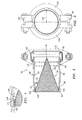
- FIG. 2 shows further details of the strainer/coupler 60.
- the sleeve 66 extends from an upstream end 80 to a downstream end 82 and has a central longitudinal axis 500.
- An exemplary sleeve length is 10cm.
- the sleeve has inner (interior) and outer (exterior) surfaces 84 and 86.
- the upstream and downstream rolled clamp grooves 88 and 90 each define an annular recess 92 in the exterior surface and a rib or annular projection 94 in the interior surface.
- Each exemplary clamp 68 and 70 has a split body, the two halves 100 and 102 (FIG. 3) which are secured to each other via a pair of diametrically opposite threaded bolt/nut assemblies 104.
- An exemplary clamp body is formed of steel and has a pair of radially inwardly-projecting upstream and downstream lips 110 and 112 (FIG. 2).
- the upstream lip of the downstream clamp 70 is compressively engaged to the sleeve in the recess 92 of the downstream groove 90.
- the downstream lip of the downstream clamp 70 is similarly compressively engaged to an upstream recess in the downstream conduit 64 of FIG. 1.
- each clamp body carries an elastomeric gasket 120 (FIG. 2) for providing a seal between the sleeve and adjacent the conduit.
- the strainer/coupler assembly 60 further includes a strainer 140.
- the exemplary strainer 140 comprises a foraminate element 142 having an upstream interior and a downstream exterior.
- the exemplary foraminate member is formed as a wire mesh (e.g., of 0.5mm stainless steel wire in a 15 mesh).
- the exemplary mesh is rolled into a generally frustoconical configuration and welded along a seam 144 (FIG. 3) to extend from a rim at an upstream end 146 of the element to a downstream end 148.
- Other forming techniques and other foraminate materials may be used.
- an upstream end portion of the foraminate member 142 is secured to a ring 150 captured within the sleeve upstream of the groove 88.
- the ring 150 is formed of sheet metal (e.g., a stainless steel strip 14mm wide and 1mm thick) having an interior surface 152 and an exterior surface 154 and upstream and downstream ends or rims 156 and 158, respectively.
- the downstream rim 158 abuts an upstream-facing end of the rib 94 to prevent downstream movement of the ring and thus the strainer element.
- the foraminate member 142 is secured to the ring such as by welding an exterior portion of the foraminate member adjacent the upstream end 146 to the interior surface 152 of the ring.
- the strainer may be inserted into the sleeve through the upstream end thereof until the ring 150 seats upstream of the groove 88.
- the ring upstream end 156 and foraminate element downstream end 148 define respective upstream and downstream ends of the strainer 140.
- the length of the foraminate element downstream of the portion secured to the ring is advantageously chosen to provide sufficient straining surface area.
- the downstream end 148 of the foraminate element is located longitudinally between the downstream groove 90 and sleeve downstream end 82.
- the downstream end 148 is located downstream of the upstream groove 88 and, more advantageously, downstream of a midpoint of the sleeve so as to provide a desired amount of surface area.
- the downstream end 148 remains upstream of the sleeve downstream end 82 so that the recessing of the strainer may protect the strainer from damage during assembly or disassembly of the inlet conduit assemblies.
- the sleeve is then placed between the adjacent conduits and the clamps are put in place and their bolts/nuts tightened to secure and seal the sleeve ends to the respective conduits. Disassembly for perodic cleaning of the strainer at a cleaning interval or replacement at a replacement interval or as may otherwise be required is by a reverse of this process.
- FIG. 5 shows an alternative strainer/coupler assembly 200 having a sleeve 202 and a strainer 204 which, except as described below, may be similar to the sleeve 66 and strainer 140 of the strainer/coupler assembly 60.
- the downstream end 205 of the foraminate element 206 is open.
- this open end is surrounded by a conduit 208 (e.g., a stainless steel tube with an upstream end 210 soldered to the exterior of the foraminate element and a downstream end 212 within a transverse conduit (e.g., a pipe) 220 extending through the sidewall of the sleeve 202.
- a conduit 208 e.g., a stainless steel tube with an upstream end 210 soldered to the exterior of the foraminate element and a downstream end 212 within a transverse conduit (e.g., a pipe) 220 extending through the sidewall of the sleeve 202.
- One end 222 of the pipe 220 within the sleeve is closed.
- the other end 224 is coupled to a valve 226 (e.g., a lever-actuated ball valve threaded into the pipe end).
- the valve 226 is closed blocking communication through the pipe 220 and, thereby, the downstream end of the strainer 204.
- the strainer operates as heretofore described. Periodically, however, the strainer may be flushed of solid contaminants by opening the valve 226 and, thereby permitting a flow from the interior of the strainer through the downstream end 205 and tube 212 into the pipe 220 and out an outlet 228 of the valve. This flushing flow may be maintained for an appropriate interval. Despite such flushing, periodically the strainer may still need to be replaced.
- Strainer replacement is eased by having a nonpermanent engagement between the strainer and the pipe 220.
- the tube 208 is closely fit within an aperture in the pipe sidewall with a clearance similar to or smaller than the mesh opening size of the strainer. This clearance advantageously permits easy removal of an old strainer and insertion of a new strainer without compromising filtration.
Landscapes
- Chemical & Material Sciences (AREA)
- Chemical Kinetics & Catalysis (AREA)
- Engineering & Computer Science (AREA)
- General Engineering & Computer Science (AREA)
- Mechanical Engineering (AREA)
- Filtration Of Liquid (AREA)
- Heat-Exchange Devices With Radiators And Conduit Assemblies (AREA)
- Devices That Are Associated With Refrigeration Equipment (AREA)
- Separation Using Semi-Permeable Membranes (AREA)
Abstract
Description
Claims (17)
- An apparatus (60;200) comprising:a conduit (66;202) having:a first end (80);
interior and exterior surfaces (84,86) extending downstream from the first end (80); anda projection (94) on the interior surface (84); anda strainer (140;204) having:a first end (146) and a second end (148;205); an upstream portion (150) positioned engaging said projection to resist downstream shifting of the strainer (140;204); anda strainer body (142;206) at least partially downstream of the upstream portion (150). - The apparatus of claim 1 wherein the conduit is a first conduit and the apparatus further comprises a second conduit (220) extending through a sidewall of the first conduit (202) and having a first portion in fluid communication with a downstream portion (205) of the strainer (206) and a second portion coupled to a valve (226) for selectively establishing communication between the strainer and a destination external to the first conduit.
- The apparatus of claim 1 or 2 being a coupler for connecting first and second fluid conducting members (62,64) and extending along an axis between said conduit first end (80) and a conduit second end (82).
- The apparatus of claim 3 wherein the exterior surface (86) proximate said conduit first and second ends (80,82) is adapted for connection to said first and second fluid conducting members (62,64).
- The apparatus of claim 3 or 4 further comprising first and second clamps (68) for respectively securing the conduit (66) to the first and second fluid conducting members (62,64).
- The apparatus of any preceding claim wherein the exterior surface (86) has:a first recess (92) at a first location closer to the first end (80) than to the second end (82); anda second recess (92) in the exterior surface at a second location closer to the second end (82) than to the first end (80).
- The apparatus of any preceding claim wherein the exterior surface (86) has a first recess (92) axially aligned with the projection (94).
- The apparatus of any preceding claim wherein the exterior surface (86) has means for engaging a clamp (68) .
- An apparatus comprising:a metallic sleeve (66;202) having:interior and exterior surfaces (84,86) extending from a first end (80) to a second end (82), a downstream direction being defined from said first end toward said second end;a first annular recess (92) in the exterior surface (86) and an axially aligned annular first rib (94) in the interior surface (84) at a first location closer to the first end (80) than to the second end (80); anda second annular recess (92) in the exterior surface (86) and an axially aligned annular second rib (94) in the interior surface (84) at a second location closer to the second end (82) than to the first end (80); anda strainer (140;204) having:a first end (146) and a second end (148;205);a first portion (150) positioned engaging the sleeve (66;202) to resist downstream shifting of the strainer (140;204); anda strainer body (142;206) at least partially on a downstream side of the first rib (94).
- The apparatus of claim 9 wherein said strainer first portion (150) is positioned between the first annular rib (94) and the sleeve first end (80) and has dimensions effective to engage the first rib (94) to so resist downstream shifting of the strainer.
- The apparatus of claim 9 or 10 further comprising first and second clamps (68), each having radially inwardly directed upstream and downstream lips (110,112) and a sealed body (120) therebetween, the downstream lip (112) of the first clamp (68) being compressively engaged to the sleeve (66;202) in the first recess (92) and the upstream lip (110) of the second clamp (68) being compressively engaged to the sleeve (66;202) in the second recess (92).
- The apparatus of any of claims 9 to 11 wherein the strainer body (142;206) has a frustoconical sidewall extending from upstream of said first rib (94) to said strainer second end (148;205).
- The apparatus of any of claims 9 to 13 wherein:the strainer first portion comprises a sheet metal sleeve (150); andthe strainer body comprises a frustoconical sidewall (142;206) secured to said sheet metal sleeve (150) and extending downstream of said first rib (94) to a radially-extending end portion at said strainer second end.
- The apparatus of any of claims 9 to 13 wherein:the strainer body (142,206) consists essentially of a wire mesh.
- A system (30) comprising:wherein the inlet conduit comprises an assembly of:a heat exchanger having first and second flows in thermal communication; anda first pump (24) driving said first flow and having an inlet conduit for receiving the first flow and an outlet conduit coupled to the heat exchanger for delivering the first flow,an upstream conduit (62);a downstream conduit (64), optionally integral with the first pump (24);an intermediate conduit (66);means (140;204) for straining the first flow;means (68) for coupling the intermediate conduit (66) to the upstream and downstream conduits (62,64).
- The system of claim 15 further comprising:wherein the second pump inlet conduit comprises an assembly of:a second pump (26) driving said second flow an having an inlet conduit for receiving the second flow and an outlet conduit coupled to the heat exchanger for delivering the second flow,an upstream conduit (62);a downstream conduit (64), optionally integral with the second pump (26);an intermediate conduit (66);means (140;204) for straining the second flow; andmeans (68) for coupling the second pump intermediate conduit (66) to the second pump upstream and downstream conduits (62,64).
- An apparatus (60;200) comprising:a conduit (66;202) having:a first end (80);
interior and exterior surfaces (84.86) extending downstream from the first end (80);a projection (94) on the interior surface (84); anda strainer (140;204) having:a first end (146) and a second end (148;205); an upstream portion (150) positioned engaging said conduit (66) to resist downstream shifting of the strainer (140;204); anda strainer body (142;206) at least partially downstream of the upstream portion (150).
Applications Claiming Priority (2)
| Application Number | Priority Date | Filing Date | Title |
|---|---|---|---|
| US350634 | 2003-01-24 | ||
| US10/350,634 US6955266B2 (en) | 2003-01-24 | 2003-01-24 | Strainer |
Publications (3)
| Publication Number | Publication Date |
|---|---|
| EP1440720A2 true EP1440720A2 (en) | 2004-07-28 |
| EP1440720A3 EP1440720A3 (en) | 2005-03-09 |
| EP1440720B1 EP1440720B1 (en) | 2011-07-06 |
Family
ID=32594946
Family Applications (1)
| Application Number | Title | Priority Date | Filing Date |
|---|---|---|---|
| EP04250375A Expired - Lifetime EP1440720B1 (en) | 2003-01-24 | 2004-01-23 | Strainer |
Country Status (4)
| Country | Link |
|---|---|
| US (2) | US6955266B2 (en) |
| EP (1) | EP1440720B1 (en) |
| AT (1) | ATE515306T1 (en) |
| ES (1) | ES2364751T3 (en) |
Families Citing this family (11)
| Publication number | Priority date | Publication date | Assignee | Title |
|---|---|---|---|---|
| KR20070004340A (en) * | 2005-07-04 | 2007-01-09 | 삼성전자주식회사 | Piping type filter and air conditioner with same |
| US7473359B1 (en) * | 2007-07-09 | 2009-01-06 | Barrett Ii F Madison | System for straining water |
| JP5076950B2 (en) * | 2008-02-14 | 2012-11-21 | アイシン精機株式会社 | Air conditioner strainer |
| US8282823B2 (en) * | 2010-03-04 | 2012-10-09 | Terragroup Corporation | Lightweight modular water purification system with reconfigurable pump power options |
| MX2016011472A (en) * | 2014-05-19 | 2017-04-06 | Illinois Tool Works | Filter coupling. |
| US9387421B1 (en) | 2015-07-14 | 2016-07-12 | Neptune-Benson, Llc | Strainer and strainer control system |
| BR112020012032B1 (en) * | 2017-12-15 | 2023-10-17 | Fmc Technologies Do Brasil Ltda | PIG ROUTING INSERT FOR PIGGABLE SYSTEM FOR UNDERWATER EQUIPMENT WITH BLOCK STRUCTURE |
| DE102019121342B4 (en) * | 2018-08-15 | 2021-03-18 | Mann+Hummel Gmbh | Filter element for use as a particle filter in a cooling circuit of an electrochemical energy converter and use of the filter element in an arrangement with an electrochemical energy converter and a cooling circuit |
| US12498071B1 (en) * | 2021-11-12 | 2025-12-16 | Sani-Matic, Inc. | Hygienic process coupling assembly |
| US11731064B1 (en) * | 2022-06-14 | 2023-08-22 | Hydrevolve Inc. | Fluid filter device and process |
| EP4400195B1 (en) * | 2023-01-11 | 2026-03-04 | Stäubli Hamburg GmbH | Filter arrangement and a half coupling element comprising a filter arrangement |
Family Cites Families (14)
| Publication number | Priority date | Publication date | Assignee | Title |
|---|---|---|---|---|
| US1782531A (en) * | 1928-09-27 | 1930-11-25 | Anthony H G Fokker | Method and means for filtering fluids |
| US1971120A (en) * | 1931-11-19 | 1934-08-21 | Rice William Hubert | Hose and nozzle coupling |
| US2658625A (en) * | 1948-08-02 | 1953-11-10 | Arthur W Rafferty | Header strainer for liquid lines |
| US2686596A (en) * | 1952-01-07 | 1954-08-17 | Ind Wire Cloth Products Corp | Dehydrator |
| US2893563A (en) * | 1954-07-12 | 1959-07-07 | Edward W Bottum | Strainer |
| US3351352A (en) * | 1962-02-27 | 1967-11-07 | Victaulic Co Of America | Gasket for pipe joint |
| US3700112A (en) * | 1970-06-08 | 1972-10-24 | Sozaburo Maeshiba | Hose coupling |
| US4277952A (en) * | 1978-07-27 | 1981-07-14 | Martinez Jr George | Method and apparatus for conserving energy in an air conditioning system |
| US4427547A (en) * | 1982-01-25 | 1984-01-24 | Quantum Systems Corporation | Backwashing-type filtering apparatus with filter support grid of ring-like segments |
| US4725364A (en) * | 1982-04-05 | 1988-02-16 | Basf Corporation | Laminar flow filtration process |
| US4582605A (en) * | 1984-05-07 | 1986-04-15 | R-P & C Valve Inc. | In-line pipeline strainer |
| US5395524A (en) * | 1992-12-10 | 1995-03-07 | Multistack, Inc. | Apparatus for filtering a fluid in a fluid supply conduit |
| US6592758B2 (en) * | 2000-02-04 | 2003-07-15 | Delaware Capital Formation, Inc. | Filter element for a liquid-state process stream |
| JP2001255045A (en) * | 2000-03-13 | 2001-09-21 | Yamaha Motor Co Ltd | Refrigerant circulation type heat transfer device |
-
2003
- 2003-01-24 US US10/350,634 patent/US6955266B2/en not_active Expired - Lifetime
-
2004
- 2004-01-23 AT AT04250375T patent/ATE515306T1/en not_active IP Right Cessation
- 2004-01-23 EP EP04250375A patent/EP1440720B1/en not_active Expired - Lifetime
- 2004-01-23 ES ES04250375T patent/ES2364751T3/en not_active Expired - Lifetime
-
2005
- 2005-02-22 US US11/063,419 patent/US7063783B2/en not_active Expired - Lifetime
Also Published As
| Publication number | Publication date |
|---|---|
| EP1440720B1 (en) | 2011-07-06 |
| US6955266B2 (en) | 2005-10-18 |
| EP1440720A3 (en) | 2005-03-09 |
| ATE515306T1 (en) | 2011-07-15 |
| ES2364751T3 (en) | 2011-09-13 |
| US7063783B2 (en) | 2006-06-20 |
| US20040144105A1 (en) | 2004-07-29 |
| US20050145551A1 (en) | 2005-07-07 |
Similar Documents
| Publication | Publication Date | Title |
|---|---|---|
| EP1440720B1 (en) | Strainer | |
| US20210205738A1 (en) | Filter assembly for plate heat exchangers and method of cleaning a working medium in a plate heat exchanger | |
| US20160146399A1 (en) | Nozzle-type steam trap | |
| US6722422B1 (en) | Heat exchange system with improved flow velocity adjustment mechanism | |
| US7013565B1 (en) | Removable collector for liquid cooled exhaust | |
| JP4221348B2 (en) | Connection structure between flange piping and connection structure between flange piping and fluid equipment | |
| JP2014145553A (en) | Double-pipe type heat exchanger | |
| KR20110017309A (en) | Heat exchanger for refrigeration unit | |
| JP2001082836A (en) | Liquid receiver | |
| US7823395B2 (en) | Universal coupling device | |
| US7618533B2 (en) | Filter system for an automobile engine | |
| JPH0694333A (en) | Three-way valve for refrigerator | |
| PL201780B1 (en) | Condenser for motor vehicles | |
| JP3055012B2 (en) | Condensate discharge device | |
| US5395524A (en) | Apparatus for filtering a fluid in a fluid supply conduit | |
| EP1206658A2 (en) | Control valve unit | |
| KR200230337Y1 (en) | y type strainer | |
| KR100502361B1 (en) | Refrigerant filter fastening device | |
| US20250085037A1 (en) | Variable refrigerant flow assembly with quick connection and serviceable filter | |
| CN217465438U (en) | Heat exchanger | |
| KR20160117376A (en) | Manufacturing method for heat exchanger with i-o pipe connecting member for heat exchanger | |
| JPH0313517B2 (en) | ||
| KR20040098911A (en) | Strainer having manometer | |
| JPH0655076U (en) | Heat exchanger | |
| KR200430670Y1 (en) | Bottom cap structure of receiver dryer |
Legal Events
| Date | Code | Title | Description |
|---|---|---|---|
| PUAI | Public reference made under article 153(3) epc to a published international application that has entered the european phase |
Free format text: ORIGINAL CODE: 0009012 |
|
| AK | Designated contracting states |
Kind code of ref document: A2 Designated state(s): AT BE BG CH CY CZ DE DK EE ES FI FR GB GR HU IE IT LI LU MC NL PT RO SE SI SK TR |
|
| AX | Request for extension of the european patent |
Extension state: AL LT LV MK |
|
| PUAL | Search report despatched |
Free format text: ORIGINAL CODE: 0009013 |
|
| AK | Designated contracting states |
Kind code of ref document: A3 Designated state(s): AT BE BG CH CY CZ DE DK EE ES FI FR GB GR HU IE IT LI LU MC NL PT RO SE SI SK TR |
|
| AX | Request for extension of the european patent |
Extension state: AL LT LV MK |
|
| 17P | Request for examination filed |
Effective date: 20050909 |
|
| AKX | Designation fees paid |
Designated state(s): AT BE BG CH CY CZ DE DK EE ES FI FR GB GR HU IE IT LI LU MC NL PT RO SE SI SK TR |
|
| 17Q | First examination report despatched |
Effective date: 20060914 |
|
| RAP1 | Party data changed (applicant data changed or rights of an application transferred) |
Owner name: CARRIER CORPORATION |
|
| GRAP | Despatch of communication of intention to grant a patent |
Free format text: ORIGINAL CODE: EPIDOSNIGR1 |
|
| GRAS | Grant fee paid |
Free format text: ORIGINAL CODE: EPIDOSNIGR3 |
|
| GRAA | (expected) grant |
Free format text: ORIGINAL CODE: 0009210 |
|
| AK | Designated contracting states |
Kind code of ref document: B1 Designated state(s): AT BE BG CH CY CZ DE DK EE ES FI FR GB GR HU IE IT LI LU MC NL PT RO SE SI SK TR |
|
| REG | Reference to a national code |
Ref country code: GB Ref legal event code: FG4D |
|
| REG | Reference to a national code |
Ref country code: DE Ref legal event code: R082 Ref document number: 602004033350 Country of ref document: DE Representative=s name: KLUNKER, SCHMITT-NILSON, HIRSCH, DE Ref country code: DE Ref legal event code: R082 Ref document number: 602004033350 Country of ref document: DE Representative=s name: SCHMITT-NILSON SCHRAUD WAIBEL WOHLFROM PATENTA, DE |
|
| REG | Reference to a national code |
Ref country code: CH Ref legal event code: EP |
|
| REG | Reference to a national code |
Ref country code: IE Ref legal event code: FG4D |
|
| REG | Reference to a national code |
Ref country code: DE Ref legal event code: R096 Ref document number: 602004033350 Country of ref document: DE Effective date: 20110901 |
|
| REG | Reference to a national code |
Ref country code: ES Ref legal event code: FG2A Ref document number: 2364751 Country of ref document: ES Kind code of ref document: T3 Effective date: 20110913 |
|
| REG | Reference to a national code |
Ref country code: NL Ref legal event code: VDEP Effective date: 20110706 |
|
| PG25 | Lapsed in a contracting state [announced via postgrant information from national office to epo] |
Ref country code: SI Free format text: LAPSE BECAUSE OF FAILURE TO SUBMIT A TRANSLATION OF THE DESCRIPTION OR TO PAY THE FEE WITHIN THE PRESCRIBED TIME-LIMIT Effective date: 20110706 |
|
| REG | Reference to a national code |
Ref country code: AT Ref legal event code: MK05 Ref document number: 515306 Country of ref document: AT Kind code of ref document: T Effective date: 20110706 |
|
| PG25 | Lapsed in a contracting state [announced via postgrant information from national office to epo] |
Ref country code: FI Free format text: LAPSE BECAUSE OF FAILURE TO SUBMIT A TRANSLATION OF THE DESCRIPTION OR TO PAY THE FEE WITHIN THE PRESCRIBED TIME-LIMIT Effective date: 20110706 Ref country code: BE Free format text: LAPSE BECAUSE OF FAILURE TO SUBMIT A TRANSLATION OF THE DESCRIPTION OR TO PAY THE FEE WITHIN THE PRESCRIBED TIME-LIMIT Effective date: 20110706 Ref country code: NL Free format text: LAPSE BECAUSE OF FAILURE TO SUBMIT A TRANSLATION OF THE DESCRIPTION OR TO PAY THE FEE WITHIN THE PRESCRIBED TIME-LIMIT Effective date: 20110706 Ref country code: SE Free format text: LAPSE BECAUSE OF FAILURE TO SUBMIT A TRANSLATION OF THE DESCRIPTION OR TO PAY THE FEE WITHIN THE PRESCRIBED TIME-LIMIT Effective date: 20110706 Ref country code: PT Free format text: LAPSE BECAUSE OF FAILURE TO SUBMIT A TRANSLATION OF THE DESCRIPTION OR TO PAY THE FEE WITHIN THE PRESCRIBED TIME-LIMIT Effective date: 20111107 |
|
| PG25 | Lapsed in a contracting state [announced via postgrant information from national office to epo] |
Ref country code: CY Free format text: LAPSE BECAUSE OF FAILURE TO SUBMIT A TRANSLATION OF THE DESCRIPTION OR TO PAY THE FEE WITHIN THE PRESCRIBED TIME-LIMIT Effective date: 20110706 Ref country code: AT Free format text: LAPSE BECAUSE OF FAILURE TO SUBMIT A TRANSLATION OF THE DESCRIPTION OR TO PAY THE FEE WITHIN THE PRESCRIBED TIME-LIMIT Effective date: 20110706 Ref country code: GR Free format text: LAPSE BECAUSE OF FAILURE TO SUBMIT A TRANSLATION OF THE DESCRIPTION OR TO PAY THE FEE WITHIN THE PRESCRIBED TIME-LIMIT Effective date: 20111007 |
|
| PG25 | Lapsed in a contracting state [announced via postgrant information from national office to epo] |
Ref country code: SK Free format text: LAPSE BECAUSE OF FAILURE TO SUBMIT A TRANSLATION OF THE DESCRIPTION OR TO PAY THE FEE WITHIN THE PRESCRIBED TIME-LIMIT Effective date: 20110706 Ref country code: CZ Free format text: LAPSE BECAUSE OF FAILURE TO SUBMIT A TRANSLATION OF THE DESCRIPTION OR TO PAY THE FEE WITHIN THE PRESCRIBED TIME-LIMIT Effective date: 20110706 |
|
| PLBE | No opposition filed within time limit |
Free format text: ORIGINAL CODE: 0009261 |
|
| STAA | Information on the status of an ep patent application or granted ep patent |
Free format text: STATUS: NO OPPOSITION FILED WITHIN TIME LIMIT |
|
| PG25 | Lapsed in a contracting state [announced via postgrant information from national office to epo] |
Ref country code: RO Free format text: LAPSE BECAUSE OF FAILURE TO SUBMIT A TRANSLATION OF THE DESCRIPTION OR TO PAY THE FEE WITHIN THE PRESCRIBED TIME-LIMIT Effective date: 20110706 Ref country code: EE Free format text: LAPSE BECAUSE OF FAILURE TO SUBMIT A TRANSLATION OF THE DESCRIPTION OR TO PAY THE FEE WITHIN THE PRESCRIBED TIME-LIMIT Effective date: 20110706 |
|
| 26N | No opposition filed |
Effective date: 20120411 |
|
| PG25 | Lapsed in a contracting state [announced via postgrant information from national office to epo] |
Ref country code: DK Free format text: LAPSE BECAUSE OF FAILURE TO SUBMIT A TRANSLATION OF THE DESCRIPTION OR TO PAY THE FEE WITHIN THE PRESCRIBED TIME-LIMIT Effective date: 20110706 |
|
| REG | Reference to a national code |
Ref country code: DE Ref legal event code: R097 Ref document number: 602004033350 Country of ref document: DE Effective date: 20120411 |
|
| PG25 | Lapsed in a contracting state [announced via postgrant information from national office to epo] |
Ref country code: MC Free format text: LAPSE BECAUSE OF NON-PAYMENT OF DUE FEES Effective date: 20120131 |
|
| REG | Reference to a national code |
Ref country code: CH Ref legal event code: PL |
|
| REG | Reference to a national code |
Ref country code: IE Ref legal event code: MM4A |
|
| PG25 | Lapsed in a contracting state [announced via postgrant information from national office to epo] |
Ref country code: CH Free format text: LAPSE BECAUSE OF NON-PAYMENT OF DUE FEES Effective date: 20120131 Ref country code: LI Free format text: LAPSE BECAUSE OF NON-PAYMENT OF DUE FEES Effective date: 20120131 |
|
| PG25 | Lapsed in a contracting state [announced via postgrant information from national office to epo] |
Ref country code: IE Free format text: LAPSE BECAUSE OF NON-PAYMENT OF DUE FEES Effective date: 20120123 |
|
| PG25 | Lapsed in a contracting state [announced via postgrant information from national office to epo] |
Ref country code: BG Free format text: LAPSE BECAUSE OF FAILURE TO SUBMIT A TRANSLATION OF THE DESCRIPTION OR TO PAY THE FEE WITHIN THE PRESCRIBED TIME-LIMIT Effective date: 20111006 |
|
| PG25 | Lapsed in a contracting state [announced via postgrant information from national office to epo] |
Ref country code: TR Free format text: LAPSE BECAUSE OF FAILURE TO SUBMIT A TRANSLATION OF THE DESCRIPTION OR TO PAY THE FEE WITHIN THE PRESCRIBED TIME-LIMIT Effective date: 20110706 |
|
| PG25 | Lapsed in a contracting state [announced via postgrant information from national office to epo] |
Ref country code: LU Free format text: LAPSE BECAUSE OF NON-PAYMENT OF DUE FEES Effective date: 20120123 |
|
| PGFP | Annual fee paid to national office [announced via postgrant information from national office to epo] |
Ref country code: IT Payment date: 20140115 Year of fee payment: 11 |
|
| PG25 | Lapsed in a contracting state [announced via postgrant information from national office to epo] |
Ref country code: HU Free format text: LAPSE BECAUSE OF FAILURE TO SUBMIT A TRANSLATION OF THE DESCRIPTION OR TO PAY THE FEE WITHIN THE PRESCRIBED TIME-LIMIT Effective date: 20040123 |
|
| PGFP | Annual fee paid to national office [announced via postgrant information from national office to epo] |
Ref country code: GB Payment date: 20150121 Year of fee payment: 12 |
|
| REG | Reference to a national code |
Ref country code: FR Ref legal event code: PLFP Year of fee payment: 13 |
|
| PG25 | Lapsed in a contracting state [announced via postgrant information from national office to epo] |
Ref country code: IT Free format text: LAPSE BECAUSE OF NON-PAYMENT OF DUE FEES Effective date: 20150123 |
|
| GBPC | Gb: european patent ceased through non-payment of renewal fee |
Effective date: 20160123 |
|
| PG25 | Lapsed in a contracting state [announced via postgrant information from national office to epo] |
Ref country code: GB Free format text: LAPSE BECAUSE OF NON-PAYMENT OF DUE FEES Effective date: 20160123 |
|
| REG | Reference to a national code |
Ref country code: FR Ref legal event code: PLFP Year of fee payment: 14 |
|
| REG | Reference to a national code |
Ref country code: DE Ref legal event code: R082 Ref document number: 602004033350 Country of ref document: DE Representative=s name: SCHMITT-NILSON SCHRAUD WAIBEL WOHLFROM PATENTA, DE |
|
| REG | Reference to a national code |
Ref country code: FR Ref legal event code: PLFP Year of fee payment: 15 |
|
| PGFP | Annual fee paid to national office [announced via postgrant information from national office to epo] |
Ref country code: FR Payment date: 20181220 Year of fee payment: 16 |
|
| PGFP | Annual fee paid to national office [announced via postgrant information from national office to epo] |
Ref country code: DE Payment date: 20181218 Year of fee payment: 16 Ref country code: ES Payment date: 20190201 Year of fee payment: 16 |
|
| REG | Reference to a national code |
Ref country code: DE Ref legal event code: R119 Ref document number: 602004033350 Country of ref document: DE |
|
| PG25 | Lapsed in a contracting state [announced via postgrant information from national office to epo] |
Ref country code: FR Free format text: LAPSE BECAUSE OF NON-PAYMENT OF DUE FEES Effective date: 20200131 Ref country code: DE Free format text: LAPSE BECAUSE OF NON-PAYMENT OF DUE FEES Effective date: 20200801 |
|
| REG | Reference to a national code |
Ref country code: ES Ref legal event code: FD2A Effective date: 20210603 |
|
| PG25 | Lapsed in a contracting state [announced via postgrant information from national office to epo] |
Ref country code: ES Free format text: LAPSE BECAUSE OF NON-PAYMENT OF DUE FEES Effective date: 20200124 |