EP1440221B1 - Combination well kick off and gas lift booster unit - Google Patents
Combination well kick off and gas lift booster unit Download PDFInfo
- Publication number
- EP1440221B1 EP1440221B1 EP02801400A EP02801400A EP1440221B1 EP 1440221 B1 EP1440221 B1 EP 1440221B1 EP 02801400 A EP02801400 A EP 02801400A EP 02801400 A EP02801400 A EP 02801400A EP 1440221 B1 EP1440221 B1 EP 1440221B1
- Authority
- EP
- European Patent Office
- Prior art keywords
- gas
- fluid
- well
- pump
- multiphase pump
- Prior art date
- Legal status (The legal status is an assumption and is not a legal conclusion. Google has not performed a legal analysis and makes no representation as to the accuracy of the status listed.)
- Expired - Lifetime
Links
- 239000007789 gas Substances 0.000 claims description 245
- 239000012530 fluid Substances 0.000 claims description 174
- IJGRMHOSHXDMSA-UHFFFAOYSA-N Atomic nitrogen Chemical compound N#N IJGRMHOSHXDMSA-UHFFFAOYSA-N 0.000 claims description 32
- 239000007788 liquid Substances 0.000 claims description 27
- 238000000034 method Methods 0.000 claims description 26
- 238000005553 drilling Methods 0.000 claims description 16
- 238000002347 injection Methods 0.000 claims description 16
- 239000007924 injection Substances 0.000 claims description 16
- 238000004519 manufacturing process Methods 0.000 claims description 16
- 229910052757 nitrogen Inorganic materials 0.000 claims description 16
- 239000007787 solid Substances 0.000 claims description 16
- 238000004140 cleaning Methods 0.000 claims description 14
- XLYOFNOQVPJJNP-UHFFFAOYSA-N water Substances O XLYOFNOQVPJJNP-UHFFFAOYSA-N 0.000 claims description 13
- 238000004064 recycling Methods 0.000 claims description 8
- 239000004576 sand Substances 0.000 claims description 8
- 230000009467 reduction Effects 0.000 claims description 7
- 238000009826 distribution Methods 0.000 claims description 5
- 229930195733 hydrocarbon Natural products 0.000 claims description 5
- 150000002430 hydrocarbons Chemical class 0.000 claims description 5
- 238000005086 pumping Methods 0.000 claims description 4
- 230000004936 stimulating effect Effects 0.000 claims description 4
- 239000004215 Carbon black (E152) Substances 0.000 claims description 2
- 238000004891 communication Methods 0.000 claims 2
- 230000015572 biosynthetic process Effects 0.000 description 15
- 238000005755 formation reaction Methods 0.000 description 15
- VNWKTOKETHGBQD-UHFFFAOYSA-N methane Chemical compound C VNWKTOKETHGBQD-UHFFFAOYSA-N 0.000 description 14
- 230000002706 hydrostatic effect Effects 0.000 description 13
- 239000003345 natural gas Substances 0.000 description 7
- 239000003921 oil Substances 0.000 description 7
- 239000000203 mixture Substances 0.000 description 5
- 238000000926 separation method Methods 0.000 description 5
- 238000011084 recovery Methods 0.000 description 4
- 230000008569 process Effects 0.000 description 3
- 230000000638 stimulation Effects 0.000 description 3
- VEXZGXHMUGYJMC-UHFFFAOYSA-N Hydrochloric acid Chemical compound Cl VEXZGXHMUGYJMC-UHFFFAOYSA-N 0.000 description 2
- 239000002253 acid Substances 0.000 description 2
- 230000006378 damage Effects 0.000 description 2
- 230000007812 deficiency Effects 0.000 description 2
- 229910001873 dinitrogen Inorganic materials 0.000 description 2
- 239000000463 material Substances 0.000 description 2
- QJGQUHMNIGDVPM-UHFFFAOYSA-N nitrogen(.) Chemical compound [N] QJGQUHMNIGDVPM-UHFFFAOYSA-N 0.000 description 2
- 239000008188 pellet Substances 0.000 description 2
- 230000001052 transient effect Effects 0.000 description 2
- BVKZGUZCCUSVTD-UHFFFAOYSA-L Carbonate Chemical compound [O-]C([O-])=O BVKZGUZCCUSVTD-UHFFFAOYSA-L 0.000 description 1
- 229910000831 Steel Inorganic materials 0.000 description 1
- 238000010306 acid treatment Methods 0.000 description 1
- 230000009471 action Effects 0.000 description 1
- 230000002411 adverse Effects 0.000 description 1
- 230000033228 biological regulation Effects 0.000 description 1
- 229910010293 ceramic material Inorganic materials 0.000 description 1
- 230000008859 change Effects 0.000 description 1
- 238000005520 cutting process Methods 0.000 description 1
- 230000007423 decrease Effects 0.000 description 1
- 230000009977 dual effect Effects 0.000 description 1
- 230000000694 effects Effects 0.000 description 1
- 230000005484 gravity Effects 0.000 description 1
- 238000002955 isolation Methods 0.000 description 1
- 239000002245 particle Substances 0.000 description 1
- 239000011347 resin Substances 0.000 description 1
- 229920005989 resin Polymers 0.000 description 1
- 230000004044 response Effects 0.000 description 1
- 230000002441 reversible effect Effects 0.000 description 1
- 230000037380 skin damage Effects 0.000 description 1
- 239000010802 sludge Substances 0.000 description 1
- 239000010959 steel Substances 0.000 description 1
- 230000001960 triggered effect Effects 0.000 description 1
Images




Classifications
-
- E—FIXED CONSTRUCTIONS
- E21—EARTH OR ROCK DRILLING; MINING
- E21B—EARTH OR ROCK DRILLING; OBTAINING OIL, GAS, WATER, SOLUBLE OR MELTABLE MATERIALS OR A SLURRY OF MINERALS FROM WELLS
- E21B21/00—Methods or apparatus for flushing boreholes, e.g. by use of exhaust air from motor
- E21B21/06—Arrangements for treating drilling fluids outside the borehole
- E21B21/063—Arrangements for treating drilling fluids outside the borehole by separating components
- E21B21/065—Separating solids from drilling fluids
-
- E—FIXED CONSTRUCTIONS
- E21—EARTH OR ROCK DRILLING; MINING
- E21B—EARTH OR ROCK DRILLING; OBTAINING OIL, GAS, WATER, SOLUBLE OR MELTABLE MATERIALS OR A SLURRY OF MINERALS FROM WELLS
- E21B43/00—Methods or apparatus for obtaining oil, gas, water, soluble or meltable materials or a slurry of minerals from wells
- E21B43/12—Methods or apparatus for controlling the flow of the obtained fluid to or in wells
- E21B43/121—Lifting well fluids
- E21B43/122—Gas lift
-
- E—FIXED CONSTRUCTIONS
- E21—EARTH OR ROCK DRILLING; MINING
- E21B—EARTH OR ROCK DRILLING; OBTAINING OIL, GAS, WATER, SOLUBLE OR MELTABLE MATERIALS OR A SLURRY OF MINERALS FROM WELLS
- E21B43/00—Methods or apparatus for obtaining oil, gas, water, soluble or meltable materials or a slurry of minerals from wells
- E21B43/34—Arrangements for separating materials produced by the well
- E21B43/35—Arrangements for separating materials produced by the well specially adapted for separating solids
-
- E—FIXED CONSTRUCTIONS
- E21—EARTH OR ROCK DRILLING; MINING
- E21B—EARTH OR ROCK DRILLING; OBTAINING OIL, GAS, WATER, SOLUBLE OR MELTABLE MATERIALS OR A SLURRY OF MINERALS FROM WELLS
- E21B43/00—Methods or apparatus for obtaining oil, gas, water, soluble or meltable materials or a slurry of minerals from wells
- E21B43/34—Arrangements for separating materials produced by the well
- E21B43/40—Separation associated with re-injection of separated materials
-
- F—MECHANICAL ENGINEERING; LIGHTING; HEATING; WEAPONS; BLASTING
- F04—POSITIVE - DISPLACEMENT MACHINES FOR LIQUIDS; PUMPS FOR LIQUIDS OR ELASTIC FLUIDS
- F04D—NON-POSITIVE-DISPLACEMENT PUMPS
- F04D31/00—Pumping liquids and elastic fluids at the same time
Definitions
- the present invention generally relates to a system and a method to kick off or maintain a well. More particularly, the invention relates to the use of pressurized gas to increase productivity of a well. More particularly still, the invention relates to stimulating and maintaining a well using gas from wellbore fluid or adjacent pipeline.
- Oil and gas wells include a wellbore formed in the earth to access hydrocarbon bearing formations.
- a borehole is initially formed and thereafter the borehole is lined with steel pipe, or casing in order to prevent cave in and facilitate the isolation of portions of the wellbore.
- at least one area of the wellbore casing is perforated to form a fluid path for the hydrocarbons.
- Fluids can be produced from oil and gas wells by utilizing internal pressure within a producing zone to lift the fluid through the wellbore to the surface of the earth. As a formation matures and some significant percentage of the product is recovered, a reduction of formation pressure occurs. With this reduction in formation pressure, the wellbore fluid eventually no longer flows without some form of artificial assistance, despite the presence of product in the formations.
- Artificial assistance may be accomplished in many different ways. However, one common form of artificial assistance is the use of a gas such as nitrogen to lighten the wellbore fluid to allow the wellbore fluid to flow out of the wellbore. The following are several examples illustrating how artificial assistance may be used to stimulate the wellbore or efficiently perform a downhole operation.
- a gas such as nitrogen
- artificial assistance is used to stimulate a shut-in well.
- a wellbore becomes shut-in as the internal formation pressure becomes insufficient to urge fluid to the surface of the well allowing back pressure from a hydrostatic head of fluid in the wellbore to stop the well from producing. This is known in the industry as “killing” or “shutting-in” the well.
- some form of artificial means is needed to stimulate the shut-in well and restart production.
- One common method is the use of nitrogen to stimulate or "kick off" the well.
- nitrogen arrives at the well site in a liquid state along with injection equipment.
- Nitrogen injection equipment typically includes a pump system, reservoir of liquid nitrogen and a coiled tubing unit to inject the nitrogen into the well.
- artificial assistance may be used to clean out a well.
- the well incurs damage during drilling and completion operation called skin damage or the reservoir may be of the type that requires fracturing to achieve full commercialisation.
- some form of hydraulic fracturing treatment is used to achieve commercial success.
- hydrochloric acid treatment is used in a carbonate formation to etch open faces of induced fractures. When the treatment is complete, the fracture closes and the etched surfaces provide a high conductivity path from the reservoir to the wellbore.
- small sized particles are mixed with fracturing fluid to hold fractures open after the hydraulic fracturing treatment. This is known in the industry as "prop and frac”.
- proppants such as resin coated sand or high strength ceramic material
- fracturing mixture used to "prop and frac”.
- Proppant materials are carefully sorted for size and sphericity to provide an effective means to prop open the fractures, thereby allowing fluid from the reservoir to enter the wellbore.
- both the "acid frac" and “prop and frac” create wellbore material such as fines that may further damage the wellbore by restricting the flow of the reservoir fluid into the wellbore.
- a cleaning method using nitrogen gas is employed to clean out the sand and fines from the wellbore.
- artificial assistance may be employed to lighten the drilling fluid in a deep water drilling operation.
- a deep water drilling operation requires the pressure created by the downhole mud be maintained at a slightly greater pressure than the reservoir pressure.
- the slight difference between the pressure created by the mud weight and the reservoir pressure is known in the industry as a "trip margin".
- trip margin For example, if the pressure created by the mud weight is much greater than the reservoir pressure, the formation fluid is forced back into the reservoir, causing the reservoir to clog and not produce efficiently.
- the pressure created by the mud weight is much less than the reservoir pressure, the formation fluid will force all the mud out, damaging the wellbore.
- a gas may be injected into the wellbore to regulate the mud weight. Additionally, the reduction in drilling fluid pressure may allow casing points to be removed, thereby reducing the cost of drilling in deep water.
- Stimulating a well or increasing the efficiency of a downhole operation using pressurized gas, such as nitrogen, has several drawbacks.
- the injection equipment must be transported to the platform or the well site. Due to space limitations, especially offshore, the extra equipment is a burden.
- nitrogen injected at a lower end of a wellbore does not change the surface pressure of the well. Eventually this surface pressure may cause the well to load back up with fluid and kill the well again.
- nitrogen equipment includes a standard group of components and they are typically not designed for a specific well. This means that all the equipment must necessarily be transported to a well even though the well requires a reduced amount of pressure of gas.
- pressurized gas is also useful on wells with reduced flow rates.
- An older producing well with a reduced flow rate may need some type of pressure boost in order for its production fluid or gas production to enter a flow line with fluid from other higher pressure wells.
- Internal pressure within a producing zone in these wells may diminish over time and become insufficient to urge the fluid up the wellbore. Therefore, a gas lift injection system is used in conjunction with the internal pressure to urge the fluid up a wellbore.
- Gas lift systems require an outside gas source, a flow line, and a downhole assembly containing a string of gas lift valves with different operating pressures, and a compressor.
- the outside gas source may be natural gas brought to the low pressure well from other wells.
- the gas is compressed and injected downhole, creating pressure in the annulus between the casing and the downhole tubing.
- the gas is forced through the gas lift valves into the tubing string, starting with the gas valve located at the highest point in contact with the hydrostatic fluid column in the tubing.
- the gas As the gas enters the liquid column it carries fluid up and out of the tubing.
- the second highest valve opens, injecting gas while the higher valve closes. The sequence continues until each valve opens and closes down to the lowest valve on the string, which then remains open to continue to urge fluid up the tubing string.
- Maintaining a well using gas lift techniques has several deficiencies. For example, if adequate pressure is not available from a local gas source, gas must be pressurized offsite and returned to the well for stimulation. An additional flow line must be added or, to avoid friction loss in a line, a compressor must be installed to compress the gas from the nearby wells. Many offshore platforms do not have the space available to integrate a local separation system along with a gas lift compressor on site. Also, a source well must always be available to provide natural gas for a struggling well. Depending on the location this may be a problem for wells that are separated by long distances or if the source well flow when combined with the flow from the stimulated well will have an adverse affect.
- the present invention generally relates to a system and method for using a gas in a well.
- a system for utilizing a gas in a well includes a source of fluid and at least one multiphase pump for transporting the fluid.
- the system further includes a separator for separating the gas from the fluid and an injection means for injecting the gas into the well.
- a portion of the source fluid is from at least one nearby well.
- the gas may be used for kicking off a shut-in well by the simultaneous injection of the gas into the shut-in well and the reduction of the wellhead pressure.
- the gas may also be used for maintaining production of the well, cleaning out the well or lightening the wellbore fluid in a deep water well. Further aspects and preferred features are set out in claim 2 et seq.
- the multiphase pump may form part of a portable multiphase pump system.
- the pump system may include a support member, with the multiphase pump disposed on the support member.
- the pump system further includes a pressure compensated pump disposed on the support member, the pressure compensated pump supplies hydraulic fluid to the multiphase pump.
- the pump system also includes a power unit disposed on the support member, the power unit provides energy to the pressure compensated pump.
- the invention provides a method for recycling gas from a wellbore fluid.
- the method includes the steps of communicating the wellbore fluid to a separator and separating a gas from the wellbore fluid.
- the method further includes the steps of delivering a portion of the gas to at least one multiphase pump and pumping the gas to a well. Additional fluid from a nearby well is also communicated to the separator.
- the invention provides a fluid system that stimulates by pushing gas into the weli to lighten the hydrostatic fluid so the well can flow while simultaneously lowering the wellhead pressure of the stimulated well by pulling up on it by a multiphase pump.
- FIG. 1 illustrates an exemplary multiphase pump system 100.
- the multiphase pump system 100 may be connected to an outlet on a wellhead.
- the multiphase pump system 100 includes a multiphase pump 105, a pressure compensated pump 140 and a power unit 110 mounted on a support member 155.
- the support member 155 permits the pump system 100 to be moved as one unit.
- the multiphase pump 105 is designed to handle fluids containing one or more phases, including solids, water, gas, oil, and combinations thereof.
- the multiphase pump 105 has two pairs of driving cylinders 145, 146 placed in line with the respective vertically disposed plungers 120, 130. Although the pairs of cylinders 145, 146 are disclosed, it is contemplated that the aspects of the present invention may be used with one cylinder or any number of cylinders.
- the pressure compensated pump 140 supplies hydraulic fluid to the cylinders 145, 146 to control the movement of the plungers 120, 130.
- the power unit 110 provides energy to the pressure compensated pump 140 to drive the plungers 120, 130.
- the plungers 120, 130 are designed to move in alternating cycles.
- a limit switch is triggered towards the end of the plunger's 120 movement.
- This limit switch causes a shuttle valve (not shown) to shift.
- a swash plate (not shown) of the compensated pump 140 is caused to reverse angle, thereby redirecting the hydraulic fluid to the cylinders 146.
- the plunger 130 is pushed downward to its retracted position.
- the plunger 130 triggers a limit switch towards the end of its movement, thereby causing the pump 140 to redirect the hydraulic fluid to the cylinders 145. In this manner, plungers 120, 130 are caused to move in alternating cycles.
- suction is created as the plunger 120 moves toward an extended position.
- the suction causes fluid to enter the multiphase pump 105 through a process inlet 125 and fill a first cavity (not shown).
- the plunger 130 moves in an opposite direction toward a retracted position. This causes the plunger 130 to expel fluid to an outlet 135.
- the plungers 120, 130 move in the opposite directions causing continuous flow of fluid from the inlet 125 to the discharge 135.
- the plungers 120, 130 operate as a pair of substantially counter-synchronous fluid pumps.
- FIG 2 is a schematic view of a combination well kick off and gas lift booster fluid circuit 200.
- the fluid circuit 200 connects a wellbore outlet 210 to a wellbore inlet 240.
- the fluid circuit 200 includes the multiphase pump 105 that is connected to the outlet 210 to draw down the wellhead pressure and obtain wellbore fluid. After pressurizing the wellbore fluid in the multiphase pump 105, the wellbore fluid is pumped into a two-phase separator 205 to extract the gas from the fluid.
- the fluid portion of the wellbore fluid is sent directly into the pipeline through line 230 while the pressurized gas extracted from the wellbore fluid flows through a gas outlet 320 into a metering device 220.
- the metering device 220 selectively controls the amount of pressurized gas flow to the inlet 240 while excess gas is directed to a gas pipeline through line 235 or recombined with the pipeline fluid.
- the gas As the gas enters the well 215, the gas is typically pumped through coil tubing (not shown) in a tubing string 330 to lighten the hydrostatic fluid column in the well 215 to stimulate or maintain production.
- Figure 3 is a schematic view of a fluid circuit 300 with an alternative source 305 for kicking off a shut-in well 315.
- the hydrostatic fluid column pressure in the tubing string 330 is greater than the internal pressure of a formation 345 therefore no movement of fluid through the wellbore outlet 320.
- the hydrostatic fluid column pressure In order to kick off or stimulate the well 315 back into production, the hydrostatic fluid column pressure must be reduced by injecting gas into the well 315 and utilizing the pump 105.
- the alternative source 305 consists of non-separated wellbore fluid from a local producing well.
- other forms of alternative sources may be employed, such as gas from a reservoir, so long as they are capable of supplying a sufficient amount of gas.
- the fluid circuit 300 connects the wellbore outlet 320 to a wellbore inlet 355.
- the fluid circuit includes a valve 310 to control the amount of the alternative source 305 entering line 335.
- the alternative source 305 flows through line 335 into the multiphase pump 105. Thereafter, the source 305 is pressurized and pumped into the two-phase separator 205.
- the extracted fluids are pushed from the separator 205 to the line 230 using the separator pressure.
- the extracted pressurized gas is diverted out the gas outlet 320, where the flow is metered by the metering device 220 and directed back toward the well 315.
- the pressurized gas is forced through a gas lift injection system 325 to reduce the hydrostatic fluid column pressure in the tubing string 330.
- the gas lift injection system 325 typically includes a plurality of gas valves 340 to distribute the gas in the tubing string 330.
- the gas flows through the gas valve 340 located at the highest point in contact with the hydrostatic fluid column in the tubing string 330.
- the gas As the gas enters the liquid column it expands, forcing fluid up and out of the tubing string 330.
- the next highest valve 340 opens injecting gas while the highest valve 340 closes. The sequence continues until each valve 340 opens and closes down to the lowest valve 340 on the string, which remains open to continue to urge fluid up the tubing string 330.
- coiled tubing may be inserted into the tubing string 330 to transport pressurized gas into the tubing string 330 to stimulate the well 315. In either case, after the well 315 is stimulated, the well 315 should be maintained to extend the response of the well stimulation.
- the simultaneous injection of gas into the well 315 and the reduction of wellhead pressure by the multiphase pump 105 results in a push-pull effect.
- the gas volume required by the gas lift assembly 325 is reduced because the wellhead pressure is reduced by the multiphase pump 105. Therefore, the well 315 may be kicked off or stimulated in an effective manner.
- Figure 4 is a schematic view of a fluid circuit 400 for maintaining well 405 production.
- the fluid circuit 400 connects a wellbore outlet 420 to a wellbore inlet 440 as natural gas from a wellbore fluid is used to maintain the gas lift assembly 325.
- the pump 105 draws wellbore fluid from the wellbore outlet 420 to pressurize wellbore fluid and subsequently pump into the two-stage separator 205. Thereafter, the fluid portion is pushed from the separator 205 into the line 230 using the pressure created in the separator 205 while the extracted pressurized gas exits out the gas outlet 320. Thereafter, the gas enters the metering device 220 where a portion of the gas is returned to the well 405 for operation of the gas lift assembly 325.
- the remaining portion of gas is directed though line 410 into a gas line.
- the remaining portion of gas may be recombined with the fluid exiting out of the separator 205 or directed to other wells requiring gas for artificial assistance.
- the gas entering the well 405 is forced through the gas lift injection system 325 into the tubing string 330, thereby maintaining production.
- no additional gas lines are required to maintain the production of the well 405 since the initial gas injected into the gas injection system 325 is reused.
- the circuit 400 may optionally include a gas source 410 for providing gas for the gas injection system 325 at any desired time during operation, such as in the beginning of the operation, intermittently during operation, or continuously during operation.
- the amount of gas from the source 410 is controlled by a valve 415, thereby allowing the operator to modulate between a dual well flow and pressure regulation.
- the gas source 410 may come from a variety of sources such as wellbore fluid from a local well or a gas reservoir.
- the gas source 410 combines with the wellbore fluid of the well 405 in line 335 and thereafter enters the pump 105 through the process described above.
- the multiphase pump 105 pulls the wellbore fluid from the well 405 resulting in a reduction of wellhead pressure. In this manner, the gas volume required by the gas lift assembly 325 is reduced and production is maximized. Therefore, the well 405 is less likely to build up with a hydrostatic fluid column.
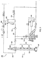
- Figure 5 shows a fluid handling circuit 500 for cleaning out a well 510 after the completion of a prop and frac job.
- the prop and frac job deposits a large amount of sand or pellets downhole to prop open a formation 540.
- the well 510 is cleaned out by injecting gas or a mixture of gas and fluid to remove the excess sand or pellets from the formation 540 allowing wellbore fluid to exit the formation 540.
- the circuit 500 connects a wellbore outlet 515 to a wellbore inlet 520.
- An optional fluid feed line 525 is connected to the well inlet 520 for supplying the liquid portion of the cleaning fluid.
- the wellbore inlet 520 may also optionally include a gas supply 530 for providing gas used to lighten the cleaning fluid at any desired time during operation, such as in the beginning of the operation, intermittently during operation, or continuously during operation.
- the primary separator 505 may consist of a pressure vessel separator or a four-phase separator.
- Four phase separators are known in the art.
- An exemplary separator suitable for use with the present invention is disclosed in U.S. Patent No. 5,857,522 issued to Bradfield, et al., which patent is herein incorporated by reference in its entirety.
- the wellbore fluid is processed in the separator 505 to produce separate streams of solid, oil, liquid, and gas. Although a four-phase separator is disclosed herein, other types of separators known to a person of ordinary skill in the art are equally applicable.
- the wellbore fluid entering into the separator 505 passes to a first stage of the separator 505.
- Solids (sludge), such as drilled cuttings, present in the wellbore fluid are removed in the first stage by gravity forces that are aided by centrifugal action of a device (not shown) disposed in the separator 505. Because solids are heavier than the remaining fluids, the solids collect at the bottom of the separator 505 and are removed therefrom through line 585.
- the remaining wellbore fluid is substantially free of solids when it passes to a second stage.
- the second stage essentially acts as a three-phase separator to separate into different streams gas, oil, and liquid present in the wellbore fluid.
- the separated gas stream varies in composition but usually includes the gas in the cleaning fluid and small amounts of entrained fine solids and liquids. Due to its composition, the gas stream is sometimes referred to as wet gas.
- the wet gas may be recycled and re-used in the cleaning operation.
- the wet gas is discharged from the separator 505 through wet gas line 560 which is connected to the well inlet 520.
- the wet gas leaving the separator 505 is low in pressure. Therefore, it would be desirable to increase the pressure of the wet gas.
- the wet gas may include three different phases, namely, solid, liquid, and gas as shown in the embodiment. Therefore, a multiphase pump 105 may be connected to the wet gas line 560 to boost the pressure of the wet gas.
- the multiphase pump 105 is designed to handle fluids containing one or more phases, including solids, water, gas, oil, and combinations thereof.
- the multiphase pump 105 may effectively increase the pressure of the wet gas in the wet gas line 560 and recycle the wet gas back to the well inlet 520.
- the fluid handling circuit 500 may significantly reduce the requirements of separation equipment for recycling the wet gas.
- the multiphase pump 105 will allow recovery or recycling of low pressure gas. In this manner, valuable wellbore fluid gas such as nitrogen and natural gas may be recycled and/or recaptured.
- the fluid handling circuit 500 may include a flare line 565 connected to the wet gas line 560.
- the flare line 565 may be used to discharge excess wet gas in the wet gas line 560.
- the flare line 565 may direct the excess wet gas to a flare stack or a collecting unit for other manners of disposal.
- the oil contained in the wellbore fluid is separated at the second stage.
- the separated oil collects in a tank (not shown) placed in the second stage of the separator 505.
- the oil is removed from the separator 505 through line 580.
- the oil is disposed in an oil tank for recovery.
- liquid that is substantially free of oil collects in a chamber or reservoir (not shown).
- the liquid consists substantially of water.
- the circuit 500 may optionally include a secondary separator (not shown) to separate out any gas remaining in the liquid before delivering it to the fluid supply 550.
- the separated gas may either be flared or delivered to the wet gas line 560 through a line (not shown) connecting line 575 to line 560. From the fluid supply 550, the liquid may be delivered to the well inlet 520 by a pump 555.
- an export line 570 may be connected to the wet gas line 560.
- the multiphase pump 105 may be used to increase the wet gas pressure to that of the export line 570. Thereafter, the wet gas may be captured and realized by directing the gas stream to the export line 570. As a result, the well 510 may start producing for an operator even before the cleaning of the well 510 is completed.
- a wet screw compressor 590 may be connected to the wet gas line 560.
- the wet screw compressor 590 is an apparatus for pumping large volumes of wet gas from a low pressure to a medium pressure.
- the wet screw compressor 590 may economically pump the wet gas into the export line 570 during the cleaning operation.
- the wet screw compressor 590 may pump the wet gas to the multiphase pump 105 at a higher pressure, thereby allowing the multiphase pump 105 to move a larger volume of wet gas to the well inlet 520.
- the wellbore fluid exiting the well outlet 515 enters the separator 505 for separation as shown in Figure 5.
- the wellbore fluid is processed in the separator 505 to produce separate streams of solids, liquids, oil, and gas.
- the solids are removed from the separator 505 through line 585.
- the oil is removed from the separator 505 through line 580.
- the liquid is removed from the separator 505 through line 575 and delivered to the fluid supply 550 for recycling.
- the gas is removed from the separator 505 through line 560. From there, the wet gas enters the multiphase pump 105 where its pressure is increased to facilitate transport through the circuit 500. Even though the wet gas contains more than one phase, the multiphase pump 105 may effectively increase the pressure of the wet gas.
- the wet gas leaving the multiphase pump 105 is directed to the well inlet 520 through line 560 and re-used.
- the export line 570 may be opened to deliver the hydrocarbons for sale or other use.
- the flare line 565 may be opened to direct wet gas to a flare stack for disposal. In this manner, the wet gas in the wellbore fluid may be recycled, collected, or otherwise disposed.
- the circuit 500 may optionally include a second gas supply 532 connected to the separator 505.
- the second gas supply 532 may be used as an additional source of gas such as nitrogen. Additionally, the second gas supply 532 may assist with transient fluid flow management common with cleaning operations.
- Figure 6 shows a fluid handling circuit 600 for assisting a deep water drilling operation.
- a deep water drilling operation includes a floating vessel 610 and a riser system 615.
- drilling fluid is pumped through a drill string 620.
- wellbore fluid a mixture of drilling fluid and formation fluid, exits up the annulus 535.
- the wellbore fluid enters the fluid handling circuit 600 through a wellbore outlet 640.
- the circuit 600 connects the wellbore outlet 640 to a wellbore inlet 645.
- the wellbore inlet 645 is connected to a gas distribution line 625.
- the gas distribution line 625 communicates gas into the annulus 535 to lighten the wellbore fluid, thereby encouraging the wellbore fluid to flow out of the annulus 535.
- the wellbore inlet 645 may optionally include a gas supply 530 for providing gas used to lighten the wellbore fluid at any desired time during operation, such as in the beginning of the operation, intermittently during operation, or continuously during operation.
- the primary separator 505 may consist of a pressure vessel separator or a four-phase separator.
- the primary separator 505 passes to a first stage where the solids are removed.
- the remaining wellbore fluid is substantially free of solids when it passes to a second stage.
- the second stage essentially acts as a three-phase separator to separate gas, oil, and liquid present in the wellbore fluid into different streams.
- the separated gas stream is referred to as wet gas.
- the wet gas may be recycled and re-used to enhance the deep water drilling operation.
- the wet gas is discharged from the separator 505 through wet gas line 560, which is connected to the well inlet 645.
- the wet gas leaving the separator 505 is low in pressure. Therefore, it would be desirable to increase the pressure of the wet gas through the multiphase pump 105.
- the multiphase pump 105 may effectively increase the pressure of the wet gas in the wet gas line 560 and recycle the wet gas back to the well inlet 645.
- the fluid handling circuit 600 may significantly reduce the requirements of separation equipment for recycling the wet gas.
- the multiphase pump 105 will allow recovery or recycling of low pressure gas. In this manner, valuable wellbore fluid gas such as nitrogen and natural gas may be recycled and/or recaptured.
- the fluid handling circuit 600 may include a flare line 565 connected to the wet gas line 560.
- the flare line 565 may be used to discharge excess wet gas in the wet gas line 560.
- the flare line 565 may direct the excess wet gas to a flare stack or a collecting unit for other manners of disposal.
- the oil contained in the wellbore fluid is separated at the second stage.
- the separated oil collects in a tank (not shown) placed in the second stage of the separator 505.
- the oil is removed from the separator 505 through line 580.
- the oil is disposed in an oil tank for recovery.
- liquid that is substantially free of oil collects in a chamber or reservoir (not shown).
- the liquid consists substantially of water. When the liquid reaches a predetermined level, it is discharged to the fluid supply 550 through line 575. In this manner, the liquid may be recycled for use during the drilling operation.
- the circuit 600 may optionally include a secondary separator (not shown) to separate out any gas remaining in the liquid before delivering it to the fluid supply 550.
- the separated gas may either be flared or delivered to the wet gas line 560 through a line (not shown) connecting line 575 to line 560. From the fluid supply 550, the liquid may be delivered to the well inlet 645 by the pump 555.
- a wet screw compressor 655 may be connected to the wet gas line 560.
- the wet screw compressor 655 is an apparatus for pumping large volumes of wet gas from a low pressure to a medium pressure.
- the wet screw compressor 655 may pump the wet gas to the multiphase pump 105 at a higher pressure, thereby allowing the multiphase pump 105 to move a larger volume of wet gas to the well inlet 645.
- the wellbore fluid exiting the well outlet 640 enters the separator 505 for separation as shown in Figure 6.
- the wellbore fluid is processed in the separator 505 to produce separate streams of solids, liquids, oil, and gas.
- the solids are removed from the separator 505 through line 585.
- the oil is removed from the separator 505 through line 580.
- the gas is removed from the separator 505 through line 560. From there, the wet gas enters the multiphase pump 105 where its pressure is increased to facilitate transport through the circuit 600. Even though the wet gas contains more than one phase, the multiphase pump 105 may effectively increase the pressure of the wet gas.
- the wet gas leaving the multiphase pump 105 is directed to the well inlet 645 through line 560 and thereafter communicated through the line 625 into the annulus 535 to lighten the wellbore fluid, thereby encouraging the wellbore fluid to flow out of the annulus 535. If excess wet gas exists, the flare line 565 may be opened to direct wet gas to a flare stack for disposal. In this manner, the wet gas in the wellbore fluid may be recycled, collected, or otherwise disposed.
- the circuit 600 may optionally include a second gas supply 532 connected to the separator 505.
- the second gas supply 532 may be used as an additional source of gas such as nitrogen. Additionally, the second gas supply 532 may assist with transient fluid flow management common with underbalanced drilling operations.
Landscapes
- Engineering & Computer Science (AREA)
- Life Sciences & Earth Sciences (AREA)
- Geology (AREA)
- Mining & Mineral Resources (AREA)
- Physics & Mathematics (AREA)
- Environmental & Geological Engineering (AREA)
- Fluid Mechanics (AREA)
- General Life Sciences & Earth Sciences (AREA)
- Geochemistry & Mineralogy (AREA)
- Mechanical Engineering (AREA)
- General Engineering & Computer Science (AREA)
- Jet Pumps And Other Pumps (AREA)
Description
Claims (47)
- A system for utilizing a gas in a well, comprising:characterised in that a portion of the source fluid is from at least one nearby well comprised in the system.a source of fluid (305);at least one multiphase pump (105) for transporting the fluid;a separator (205;505) for separating phases in the fluid so as to separate gas from the fluid;and an injector (355) for injecting the gas from the separator into the well;
- A system as claimed in claim 1, wherein the at least one multiphase pump (105) is a wet screw compressor.
- A system as claimed in claim 1, wherein the at least one multiphase pump (105) is a ram pump.
- A system as claimed in claim 3, wherein the ram pump (105) consists of a pair of plungers (120;130), each plunger movable between an extended position and a retracted position.
- A system as claimed in claim 4, wherein the plungers (120,130) are moved by a fluid operated cylinder (145,146).
- A system as claimed in any preceding claim, further including a wet screw compressor (590) to increase the volume of fluid to the at least one multiphase pump (105).
- A system as claimed in claim 6, wherein the wet screw compressor is arranged to pump a wet gas to an export line (570).
- A system as claimed in any preceding claim, wherein the well is a shut-in well (315) and the gas is used to kick off the shut-in well.
- A system as claimed in claim 8, arranged so that a first portion of the gas is injected into the shut-in well (315) and a second portion of the gas is sent to an export line (370).
- A system as claimed in claim 8 or 9, wherein the source of fluid includes an alternative (305) source in selective communication with the at least one multiphase pump.
- A system as claimed in claim 10, wherein the alternative source (305) consists of wellbore fluid from at least one wellhead.
- A system as claimed in claim 10, wherein the alternative source (305) consists of gas from a gas reservoir.
- A system as claimed in claim 10, 11 or 12, wherein the alternative source (305) provides fluid to the at least one multiphase pump (105), whereby the fluid is pressurized and pumped to the separator (205).
- A system as claimed in any of claims 8 to 13, wherein the at least one multiphase pump (105) is in communication with the shut-in well (315) to reduce a wellhead pressure in the shut-in well.
- A system as claimed in claim 14, wherein the gas injected into the shut-in well (315) and the simultaneous reduction of the wellhead pressure by the multiphase pump (105) stimulate the shut-in well.
- A system as claimed in any of claims 1 to 7, wherein the injector includes a gas lift assembly (325) and the gas is used to increase production from the well.
- A system as claimed in claim 16, wherein the fluid is communicated to the at least one multiphase pump (105) and thereby pressurized and pumped to the separator (205).
- A system as claimed in claim 16 or 17, wherein the gas is injected into the gas lift assembly (325) to increase production of the well.
- A system as claimed in any preceding claim, wherein the separator (205) removes solids and liquids from the fluid.
- A system as claimed in any of claims 1 to 7, wherein the well contains deposits of sand and the gas is used to clean out the well.
- A system as claimed in claim 20, wherein the gas is a wet gas.
- A system as claimed in claim 21, wherein the wet gas is selected from the group consisting of nitrogen, hydrocarbon, and combinations thereof.
- A system as claimed in claim 21 or 22, wherein a first portion of the wet gas is communicated to the at least one multiphase pump to be pressurized and a second portion of the wet gas is communicated to an export line.
- A system as claimed in claim 21, 22 or 23, wherein the wet gas is pumped into the well to remove the sand from the well.
- A system as claimed in any of claims 1 to 7, wherein the well comprises a riser system (615), whereby the gas is used to lighten the fluid in the riser system.
- A system as claimed in claim 25, wherein the gas is a wet gas.
- A system as claimed in claim 26, wherein the wet gas is communicated to the at least one multiphase pump (105) to be pressurized and pumped through a gas distribution line to lighten the fluid flowing up the riser system (615).
- A system as claimed in any of claims 20 to 27, wherein the fluid is communicated to the separator (505).
- A system as claimed in any preceding claim, wherein the source of fluid includes the well.
- A system as claimed in any of claims 1 to 28, wherein the source of fluid comprises a gas line.
- A system as claimed in any preceding claim, wherein the multiphase pump (105) is part of a portable multiphase pump system (100), the portable multiphase pump system further comprising:a support member (155) operatively connected to the multiphase pump; anda power unit operatively connected to the multiphase pump, the power unit for providing energy to the multiphase pump.
- A system as claimed in claim 31, wherein the portable multiphase pump system (100) further comprises a pressure compensated pump (140).
- A system as claimed in claim 32, wherein the pressure compensated pump (140) is operatively connected to the multiphase pump (105) and supplies fluid to the multiphase pump.
- A method for recycling gas from a wellbore fluid, comprising:characterised by delivering additional fluid from a nearby well (305) to the separator.communicating the wellbore fluid to a separator (205;505);separating a gas from the wellbore fluid;delivering a portion of the gas to at least one multiphase pump (105); andpumping the gas to a well;
- A method as claimed in claim 34, further including the step of recycling the gas.
- A method as claimed in claim 34 or 35, wherein the gas comprises one or more phases.
- A method as claimed in claim 34, 35 or 36, further including the step of delivering the gas to an export line.
- A method as claimed in any of claims 34 to 37, wherein the at least one multiphase pump (105) is a ram pump.
- A method as claimed in claim 38, wherein the ram pump (105) consists of a pair of plungers, each plunger movable between an extended position and a retracted position.
- A method as claimed in claim 39, wherein the plungers (120,130) are moved by a fluid operated cylinder (145,146).
- A method as claimed in any of claims 34 to 40, further comprising using a wet screw compressor (390) to increase the volume of fluid to the at least one multiphase pump (105).
- A method as claimed in claim 41, wherein the wet screw compressor (590) may pump a wet gas to an export line (570).
- A method as claimed in any of claims 34 to 42, further including the step of stimulating the production of the well.
- A method as claimed in any of claims 34 to 42, further including the step of operating a gas lift injection system (325) by forcing the wet gas into the gas lift injection system.
- A method as claimed in any of claims 34 to 42, further including the step of cleaning sand out of the well.
- A method as claimed in any of claims 34 to 42, further including the step of drilling a deep water well using a floating vessel (610), a riser system (615) and a gas distribution line (625).
- A method as claimed in claim 46, wherein the wet gas is communicated from floating vessel (610) through the gas distribution line (625) into the riser system (615) to lighten the wellbore fluid flowing up the riser system.
Applications Claiming Priority (3)
| Application Number | Priority Date | Filing Date | Title |
|---|---|---|---|
| US32852601P | 2001-10-11 | 2001-10-11 | |
| US328526P | 2001-10-11 | ||
| PCT/GB2002/004648 WO2003033865A1 (en) | 2001-10-11 | 2002-10-11 | Combination well kick off and gas lift booster unit |
Publications (2)
| Publication Number | Publication Date |
|---|---|
| EP1440221A1 EP1440221A1 (en) | 2004-07-28 |
| EP1440221B1 true EP1440221B1 (en) | 2005-12-07 |
Family
ID=23281338
Family Applications (1)
| Application Number | Title | Priority Date | Filing Date |
|---|---|---|---|
| EP02801400A Expired - Lifetime EP1440221B1 (en) | 2001-10-11 | 2002-10-11 | Combination well kick off and gas lift booster unit |
Country Status (3)
| Country | Link |
|---|---|
| US (1) | US20030085036A1 (en) |
| EP (1) | EP1440221B1 (en) |
| WO (1) | WO2003033865A1 (en) |
Families Citing this family (29)
| Publication number | Priority date | Publication date | Assignee | Title |
|---|---|---|---|---|
| US6966367B2 (en) * | 2002-01-08 | 2005-11-22 | Weatherford/Lamb, Inc. | Methods and apparatus for drilling with a multiphase pump |
| US7178592B2 (en) | 2002-07-10 | 2007-02-20 | Weatherford/Lamb, Inc. | Closed loop multiphase underbalanced drilling process |
| GB0227394D0 (en) * | 2002-11-23 | 2002-12-31 | Weatherford Lamb | Fluid removal from gas wells |
| CA2421376A1 (en) * | 2003-03-07 | 2004-09-07 | Robert Joseph Foster | Hybrid coiled tubing/fluid pumping unit |
| US7063161B2 (en) * | 2003-08-26 | 2006-06-20 | Weatherford/Lamb, Inc. | Artificial lift with additional gas assist |
| DE10350226B4 (en) * | 2003-10-27 | 2005-11-24 | Joh. Heinr. Bornemann Gmbh | Method for conveying multiphase mixtures and pump system |
| CA2450994C (en) * | 2003-11-27 | 2010-08-10 | Weatherford Canada Ltd. | Method and apparatus to control the rate of flow of a fluid through a conduit |
| GB2410102B (en) * | 2004-01-13 | 2007-11-28 | Weatherford Lamb | A system for evaluating over and underbalanced drilling operations |
| US7533726B2 (en) * | 2004-07-15 | 2009-05-19 | Gaskill Robert A | Method of increasing gas well production |
| WO2006039665A2 (en) * | 2004-10-01 | 2006-04-13 | Complete Production Services, Inc. | Apparatus and method for well completion |
| WO2007090193A2 (en) * | 2006-02-01 | 2007-08-09 | Petro Hydraulic Lift System, L.L.C. | Hydraulic oil well pumping apparatus |
| US7717181B2 (en) * | 2007-01-09 | 2010-05-18 | Terry Bullen | Artificial lift system |
| US8261838B2 (en) * | 2007-01-09 | 2012-09-11 | Terry Bullen | Artificial lift system |
| US20090038806A1 (en) * | 2007-08-10 | 2009-02-12 | Eog Resources, Inc. | Accumulation and recycling of captured gas in recovery of subterranean fluids |
| MX2010008298A (en) * | 2008-01-28 | 2010-11-01 | Petro Hydraulic Lift System L L C | Hydraulic oil well pumping apparatus. |
| NO328277B1 (en) * | 2008-04-21 | 2010-01-18 | Statoil Asa | Gas Compression System |
| WO2009137324A2 (en) * | 2008-05-06 | 2009-11-12 | Fmc Technologies, Inc. | Motor with high pressure rated can |
| GB2461282A (en) * | 2008-06-25 | 2009-12-30 | Expro North Sea Ltd | Downhole power generation using fluid flow and a turbine |
| US8448711B2 (en) * | 2010-09-23 | 2013-05-28 | Charles J. Miller | Pressure balanced drilling system and method using the same |
| GB201202904D0 (en) * | 2012-02-20 | 2012-04-04 | Caltec Ltd | Extra production gain with SJP system and gaslift |
| US9617837B2 (en) | 2013-01-14 | 2017-04-11 | Lufkin Industries, Llc | Hydraulic oil well pumping apparatus |
| US9644137B2 (en) * | 2014-02-04 | 2017-05-09 | Conocophillips Company | Method of cryogenic acid fracking |
| US9816335B2 (en) | 2015-05-29 | 2017-11-14 | Halliburton Energy Services, Inc. | Bypass flushing for gas extraction systems |
| CN108005621A (en) * | 2017-11-29 | 2018-05-08 | 中国石油集团渤海钻探工程有限公司 | A kind of gas drilling pit shaft drainage system and gaslift optimization method |
| CN107842343B (en) * | 2017-11-30 | 2023-08-15 | 青岛海洋地质研究所 | Gas-water-sand three-phase artificial lifting simulation experiment system applied to hydrate research |
| CN112096353B (en) * | 2019-06-17 | 2024-12-27 | 中国石油天然气股份有限公司 | Venting device and gas injection system |
| WO2021053314A1 (en) * | 2019-09-16 | 2021-03-25 | Pickernell Paul | Wellhead boosting apparatus and system |
| US11639656B1 (en) * | 2022-08-19 | 2023-05-02 | Total Gas Resource Recovery, Llc | Natural gas capture from a well stream |
| CN117780306A (en) * | 2022-09-22 | 2024-03-29 | 中国石油天然气集团有限公司 | A composite method for efficient production recovery of horizontal wells with compressed channeled shale gas |
Family Cites Families (33)
| Publication number | Priority date | Publication date | Assignee | Title |
|---|---|---|---|---|
| GB1061743A (en) * | 1963-04-24 | 1967-03-15 | Nash Engineering Co | Improvements in or relating to fluid pumping systems |
| CS189674B2 (en) * | 1973-11-19 | 1979-04-30 | Hall Thermotank Prod Ltd | Method of and apparatus for compressing gas or steam and for lubricating the compressing machine |
| US4279307A (en) * | 1979-03-09 | 1981-07-21 | P. H. Jones Hydrogeology, Inc. | Natural gas production from geopressured aquifers |
| US4319635A (en) * | 1980-02-29 | 1982-03-16 | P. H. Jones Hydrogeology, Inc. | Method for enhanced oil recovery by geopressured waterflood |
| US4553903A (en) * | 1982-02-08 | 1985-11-19 | Baruir Ashikian | Two-stage rotary compressor |
| US4477237A (en) * | 1982-05-10 | 1984-10-16 | Grable William A | Fabricated reciprocating piston pump |
| SE8602651L (en) * | 1986-06-13 | 1987-12-14 | Asea Atom Ab | The pumping device |
| GB2215402B (en) * | 1988-02-29 | 1992-06-17 | Shell Int Research | Apparatus for pumping well effluents |
| US4860830A (en) * | 1988-08-05 | 1989-08-29 | Mobil Oil Corporation | Method of cleaning a horizontal wellbore |
| US5048603A (en) * | 1990-05-29 | 1991-09-17 | Bell Larry M | Lubricator corrosion inhibitor treatment |
| DK0470883T3 (en) * | 1990-08-10 | 1995-11-27 | Inst Francais Du Petrole | Method and device for utilizing small oil fields in the seabed |
| GB9120933D0 (en) * | 1991-10-02 | 1991-11-13 | Bhr Group Ltd | Axial flow pump |
| FR2694785B1 (en) * | 1992-08-11 | 1994-09-16 | Inst Francais Du Petrole | Method and system of exploitation of petroleum deposits. |
| US5496466A (en) * | 1993-09-14 | 1996-03-05 | Teledyne Industries, Inc. | Portable water purification system with double piston pump |
| US6007306A (en) * | 1994-09-14 | 1999-12-28 | Institute Francais Du Petrole | Multiphase pumping system with feedback loop |
| US5501279A (en) * | 1995-01-12 | 1996-03-26 | Amoco Corporation | Apparatus and method for removing production-inhibiting liquid from a wellbore |
| US6089322A (en) * | 1996-12-02 | 2000-07-18 | Kelley & Sons Group International, Inc. | Method and apparatus for increasing fluid recovery from a subterranean formation |
| US5839888A (en) * | 1997-03-18 | 1998-11-24 | Geological Equipment Corp. | Well service pump systems having offset wrist pins |
| US5992517A (en) * | 1997-10-17 | 1999-11-30 | Mcanally; Charles W. | Downhole reciprocating plunger well pump system |
| US5950651A (en) * | 1997-11-10 | 1999-09-14 | Technology Commercialization Corp. | Method and device for transporting a multi-phase flow |
| US6138757A (en) * | 1998-02-24 | 2000-10-31 | Bj Services Company U.S.A. | Apparatus and method for downhole fluid phase separation |
| CA2243105C (en) * | 1998-07-10 | 2001-11-13 | Igor J. Mokrys | Vapour extraction of hydrocarbon deposits |
| FR2792678B1 (en) * | 1999-04-23 | 2001-06-15 | Inst Francais Du Petrole | ASSISTED RECOVERY OF HYDROCARBONS BY COMBINED INJECTION OF AN AQUEOUS PHASE AND AT LEAST PARTIALLY MISCIBLE GAS |
| EP1228311A4 (en) * | 1999-06-07 | 2003-02-12 | Univ Texas | PRODUCTION SYSTEM AND METHOD FOR THE PRODUCTION OF FLUIDS FROM A WELL |
| US6209641B1 (en) * | 1999-10-29 | 2001-04-03 | Atlantic Richfield Company | Method and apparatus for producing fluids while injecting gas through the same wellbore |
| NO313767B1 (en) * | 2000-03-20 | 2002-11-25 | Kvaerner Oilfield Prod As | Process for obtaining simultaneous supply of propellant fluid to multiple subsea wells and subsea petroleum production arrangement for simultaneous production of hydrocarbons from multi-subsea wells and supply of propellant fluid to the s. |
| US6607607B2 (en) * | 2000-04-28 | 2003-08-19 | Bj Services Company | Coiled tubing wellbore cleanout |
| GB0022411D0 (en) * | 2000-09-13 | 2000-11-01 | Weir Pumps Ltd | Downhole gas/water separtion and re-injection |
| NO312978B1 (en) * | 2000-10-20 | 2002-07-22 | Kvaerner Oilfield Prod As | Methods and facilities for producing reservoir fluid |
| US6454542B1 (en) * | 2000-11-28 | 2002-09-24 | Laibe Corporation | Hydraulic cylinder powered double acting duplex piston pump |
| EP1243748A1 (en) * | 2001-03-16 | 2002-09-25 | DCT Double-Cone Technology AG | Double-cone device and pump |
| GB2394259B (en) * | 2001-07-25 | 2005-05-25 | Leobersdorfer Maschf | Multistage compressor for compressing gases |
| US6644400B2 (en) * | 2001-10-11 | 2003-11-11 | Abi Technology, Inc. | Backwash oil and gas production |
-
2002
- 2002-10-11 EP EP02801400A patent/EP1440221B1/en not_active Expired - Lifetime
- 2002-10-11 WO PCT/GB2002/004648 patent/WO2003033865A1/en not_active Ceased
- 2002-10-11 US US10/269,954 patent/US20030085036A1/en not_active Abandoned
Also Published As
| Publication number | Publication date |
|---|---|
| EP1440221A1 (en) | 2004-07-28 |
| WO2003033865A1 (en) | 2003-04-24 |
| US20030085036A1 (en) | 2003-05-08 |
Similar Documents
| Publication | Publication Date | Title |
|---|---|---|
| US20030085036A1 (en) | Combination well kick off and gas lift booster unit | |
| EP1532347B1 (en) | Closed loop multiphase underbalanced drilling process | |
| US6039116A (en) | Oil and gas production with periodic gas injection | |
| EP1266122B1 (en) | Downhole separation and injection of produced water | |
| US6672392B2 (en) | Gas recovery apparatus, method and cycle having a three chamber evacuation phase for improved natural gas production and down-hole liquid management | |
| US6336503B1 (en) | Downhole separation of produced water in hydrocarbon wells, and simultaneous downhole injection of separated water and surface water | |
| US7717182B2 (en) | Artificial lift with additional gas assist | |
| EP1266123B1 (en) | Subsea production system | |
| US7100695B2 (en) | Gas recovery apparatus, method and cycle having a three chamber evacuation phase and two liquid extraction phases for improved natural gas production | |
| US20090169397A1 (en) | Method for removing fluid from a well bore | |
| EP2198120B1 (en) | Pumping module and system | |
| WO2017015264A1 (en) | A hydrocarbon production system and an associated method thereof | |
| US10794149B2 (en) | Artificial lift method and apparatus for horizontal well | |
| US6056054A (en) | Method and system for separating and injecting water in a wellbore | |
| US6668931B1 (en) | Apparatus and method for cleaning a gas well | |
| US6053249A (en) | Method and apparatus for injecting gas into a subterranean formation | |
| WO1999015755A2 (en) | Dual injection and lifting system | |
| EP1392955B1 (en) | Borehole production boosting system | |
| CN1079799A (en) | The Hoisting System of well | |
| RU2290500C1 (en) | Method for inter-well transit of liquid | |
| CA2393302C (en) | Method for cleaning a gas well | |
| RU2238400C1 (en) | System and method for restoring well productiveness and extraction of oil by pump method, including case after stopping | |
| RU2133330C1 (en) | Method for mechanized recovery of liquid hydrocarbons | |
| CN120556894A (en) | An oil-water separation and injection-production completion structure | |
| Robertson Jr et al. | Gas lift |
Legal Events
| Date | Code | Title | Description |
|---|---|---|---|
| PUAI | Public reference made under article 153(3) epc to a published international application that has entered the european phase |
Free format text: ORIGINAL CODE: 0009012 |
|
| 17P | Request for examination filed |
Effective date: 20031008 |
|
| AK | Designated contracting states |
Kind code of ref document: A1 Designated state(s): AT BE BG CH CY CZ DE DK EE ES FI FR GB GR IE IT LI LU MC NL PT SE SK TR |
|
| AX | Request for extension of the european patent |
Extension state: AL LT LV MK RO SI |
|
| 17Q | First examination report despatched |
Effective date: 20041102 |
|
| GRAP | Despatch of communication of intention to grant a patent |
Free format text: ORIGINAL CODE: EPIDOSNIGR1 |
|
| GRAS | Grant fee paid |
Free format text: ORIGINAL CODE: EPIDOSNIGR3 |
|
| REG | Reference to a national code |
Ref country code: DE Ref legal event code: 8566 |
|
| GRAA | (expected) grant |
Free format text: ORIGINAL CODE: 0009210 |
|
| AK | Designated contracting states |
Kind code of ref document: B1 Designated state(s): GB NL |
|
| REG | Reference to a national code |
Ref country code: GB Ref legal event code: FG4D |
|
| PLBE | No opposition filed within time limit |
Free format text: ORIGINAL CODE: 0009261 |
|
| STAA | Information on the status of an ep patent application or granted ep patent |
Free format text: STATUS: NO OPPOSITION FILED WITHIN TIME LIMIT |
|
| 26N | No opposition filed |
Effective date: 20060908 |
|
| REG | Reference to a national code |
Ref country code: DE Ref legal event code: 8566 |
|
| REG | Reference to a national code |
Ref country code: NL Ref legal event code: SD Effective date: 20150318 |
|
| REG | Reference to a national code |
Ref country code: GB Ref legal event code: 732E Free format text: REGISTERED BETWEEN 20151022 AND 20151028 |
|
| PGFP | Annual fee paid to national office [announced via postgrant information from national office to epo] |
Ref country code: GB Payment date: 20151007 Year of fee payment: 14 |
|
| PGFP | Annual fee paid to national office [announced via postgrant information from national office to epo] |
Ref country code: NL Payment date: 20151012 Year of fee payment: 14 |
|
| REG | Reference to a national code |
Ref country code: NL Ref legal event code: MM Effective date: 20161101 |
|
| GBPC | Gb: european patent ceased through non-payment of renewal fee |
Effective date: 20161011 |
|
| PG25 | Lapsed in a contracting state [announced via postgrant information from national office to epo] |
Ref country code: GB Free format text: LAPSE BECAUSE OF NON-PAYMENT OF DUE FEES Effective date: 20161011 |
|
| PG25 | Lapsed in a contracting state [announced via postgrant information from national office to epo] |
Ref country code: NL Free format text: LAPSE BECAUSE OF NON-PAYMENT OF DUE FEES Effective date: 20161101 |