BACKGROUND OF THE INVENTION
FIELD OF THE INVENTION
-
The present invention relates to an antenna used for mobile
radio equipment to be mounted on a vehicle or the like.
DESCRIPTION OF THE RELATED ART
-
Recently, a linear mono-pole antenna or a folded mono-pole
antenna is generally employed as an antenna for mobile radio
equipment to be mounted on a vehicle.
-
Such a conventional antenna will be described in the following
with reference to Fig. 11.
-
Fig. 11 (a) is a side view of a conventional mono-pole antenna.
The conventional mono-pole antenna comprises a flat-plate
conductive ground plane 91 made from copper material or the like,
a feeding point 92 positioned at the center of the ground plane
91, and an antenna element 93 made from linear copper material
or the like. The antenna element 93, with one end connected
to the feeding point 92 and the other end opened, is vertically
extended by height h against the ground plane 91. The mono-pole
antenna is configured in this way.
-
Also, Fig. 11 (b) is a side view of a conventional folded
mono-pole antenna. The conventional folded mono-pole antenna
has an antenna element 103 made from linear copper material or
the like which is folded in U-shape. The antenna element 103,
with one end connected to the feeding point 92, is vertically
extended by height h against the ground plane 91, and its upper
part is folded in U-shape, while the other end is connected to
the ground plane 91. The folded mono-pole antenna is configured
in this way.
-
In any of the antennas configured as described above, when
high-frequency current of operating frequency is supplied to
the feeding point 92, the antenna elements 93, 103 are excited
to perform signal transmitting operation. Also, in signal
reception, the antenna elements 93, 103 are excited by the
high-frequency electromagnetic field of operating frequency to
perform signal receiving operation.
-
The mono-pole antenna is formed so that one end of the antenna
element 93 is connected to the feeding point 92 and the other
end thereof is opened. Therefore, current (i1) across a - b
and image current (i1) equivalent to across a - b flow in same
phase to the ground plane 91. The mono-pole antenna is excited
in this way, and then electromagnetic waves are emitted into
the air.
-
On the other hand, the folded mono-pole antenna is formed
so that the antenna element 103 is folded in U-shape. Therefore,
in addition to current (i1) across a - b and current (i3) across
c - d, image current (i1, i3) equivalent to across a - b and
across c - d flows in same phase to the ground plane 91. Since
the folded mono-antenna is enhanced in excitation by using such
a configuration, the band width of the antenna can be expanded.
-
As preceding technical document information regarding the
invention of this application, for example, Japanese Laid-open
Patent S62-122401 is well known.
-
However, as in a conventional mono-pole antenna and a folded
mono-pole antenna described above, the antenna is generally
operated in a 1/4 wavelength mode. Therefore, the mechanical
height h is required to be at least 1/4 wavelength of operating
frequency. For example, in the case of 900MHz band used for
cellular phones, the height required is at least 83mm that is
equivalent to 1/4 wavelength thereof.
-
Accordingly, for the reduction in size of the antenna, if
the mechanical height h of the antenna element is lowered by
making the height shorter than 1/4 wavelength of operating
frequency, then the antenna impedance is decreased, and there
arises a problem that it is difficult to adjust impedance
matching.
-
Also, when the above conventional antenna is installed on
a rear tray or dashboard in a vehicle, it is desirable to face
the antenna elements 93, 103 upward in order to improve the
electromagnetic wave emission efficiency of the antenna.
However, if the antenna elements 93, 103 are faced upward, a
large space is occupied by the antenna elements 93, 103 in the
direction of height, and there arises a problem of causing
inconvenience in use of the antenna in a vehicle.
SUMMARY OF THE INVENTION
-
The present invention is intended to solve such a problem,
and the object of the invention is to provide a small size antenna
with its antenna element lowered in height.
-
In order to achieve the purpose, the antenna of the present
invention comprises a flat-plate ground plane;
a first antenna element with its one end connected to a feeding
point and its intermediate portion folded by a plurality of times,
which is extended upward from the ground plane; and
a second antenna element with its one end connected to the
other end of the first antenna and with the other end thereof
connected to the ground plane, which has an intermediate portion
extended upward from the ground plane,
wherein the intermediate portion of the second antenna
element is disposed in a symmetrical relation with the
intermediate portion of the first antenna element.
-
Further, the antenna of the present invention is disposed
in such arrangement that the intermediate portion of the first
antenna element and the intermediate portion of the second
antenna are symmetrically opposed to each other.
-
Also, the antenna of the present invention comprises a
substrate extended upward from the ground plane, and the
intermediate portion of the first antenna element is disposed
on one surface of the substrate, while the intermediate portion
of the second antenna element is disposed on the other surface
opposing to the surface of the substrate on which the intermediate
portion of the first antenna element is disposed.
-
In this way, since the intermediate portions of the first
and the second antenna elements are folded by a plurality of
times and symmetrically opposed to each other, the antenna
impedance is increased, making it easier to adjust impedance
matching. Further, since the intermediate portion is folded
by a plurality of times and symmetrically opposed to each other,
it is possible to lower the height of the antenna.
-
Also, the antenna of the present invention is configured
in that the other end of the first antenna element is connected
to one end of the second antenna element via a conductive plate.
Therefore, the antenna impedance at the feeding point can be
increased by the conductive plate, and the antenna can be further
lowered in height. Also, the resonance frequency of the antenna
can be easily adj usted by partially notching the conductive plate
or the like, and it is possible to easily adjust the desired
resonance frequency.
-
Further, the antenna of the present invention is configured
in that the first and the second antenna elements are plate-like
elements. Accordingly, the antenna elements can be easily
formed by pressing or etching, and also the antenna
characteristics can be stabilized.
-
Also, the antenna of the present invention comprises a
plurality of parasitic antenna elements having intermediate
portions same in shape as the intermediate portion of the first
antenna element, and each of the parasitic antenna elements is
disposed in parallel with the surface where the first antenna
element and the second antenna element are disposed, and one
end of the parasitic antenna element is connected to the ground
plane, while the other end is opened. In this way, the excitation
is enhanced by each antenna element and it is possible to expand
the band of the antenna.
-
Further, the antenna of the present invention is configured
in that the intermediate portion of the first antenna element
and the intermediate portion of the second antenna element are
symmetrically arranged on same flat surface. Thus, it is
possible to reduce the thickness of the antenna.
-
Also, the antenna of the present invention is configured
in that each line length of the first antenna element and the
second antenna element is substantially an electric length of
5/4 wavelength in overall length as against the frequency band
of high-frequency current supplied. That is, since the
intermediate portion is folded by a plurality of times, it is
possible to lower the height even in case each line length of
the antenna elements is elongated. Thus, for example by making
each line length of the antenna elements equivalent to the
electric length of 5/4 wavelength that operates 1/4 wavelength
mode, it is possible to lower the height without degrading the
efficiency of radiation from the antenna into the air as compared
with the conventional antenna of 1/4 wavelength line length.
BRIEF DESCRIPTION OF THE DRAWINGS
-
- Fig. 1 is a perspective view of an antenna in the first
preferred embodiment of the present invention.
- Fig. 2 is a side view of the antenna.
- Fig. 3 (a) to Fig. 3 (b) are characteristic diagrams of the
antenna.
- Fig. 4 is a perspective view of the antenna in another
preferred embodiment.
- Fig. 5 is a perspective view of the antenna.
- Fig. 6 is a plan view showing an example of manufacturing
method for the antenna.
- Fig. 7 is a side view of an antenna in the second preferred
embodiment of the present invention.
- Fig. 8 (a) to Fig. 8 (b) are plan views of the antenna in
another preferred embodiment.
- Fig. 9 is a perspective view of the antenna.
- Fig. 10 is a perspective view of the antenna.
- Fig. 11 (a) to Fig. (b) are side views of conventional
antennas.
-
DESCRIPTION OF THE PREFERRED EMBODIMENTS
-
The preferred embodiments of the present invention will be
described in the following with reference to Fig. 1 to Fig. 10.
(First preferred embodiment)
-
Fig. 1 is a perspective view of an antenna in the first
preferred embodiment of the present invention, and Fig. 2 is
a side view of the antenna. As shown in the figure, the antenna
of the first preferred embodiment comprises flat-plate
conductive ground plane 1 using copper, steel material or the
like having lengthwise and widthwise dimensions of one wavelength
or over each and feeding point 2 positioned at nearly the center
of the ground plane 1. Further, one end 13a of first antenna
element 13 realized by using linear or plate-like copper material
is connected to the feeding point 2. The first antenna element
13 has an intermediate portion 13b extended upward from the ground
plane 1. The intermediate portion 13b is folded in nearly U-shape
with sharp corner by a plurality of times.
-
Also, one end 23a of second antenna element 23 using copper
material or the like is similarly connected to the other end
13c of the first antenna element 13 by means of connecting point
4. The second antenna element 23 also has an intermediate portion
23b extended upward from the ground plane 1 the same as the first
antenna element 13. Further, the intermediate portion 23b is,
for example, folded in nearly U-shape with sharp corner by a
plurality of times the same as the intermediate portion 13b.
Also, the other end 23c of the second antenna element 23 is
electrically connected to the ground plane 1.
-
Further, as shown in Fig. 1, the intermediate portion 23b
of the second antenna element 23 is formed in opposing and
symmetrical relation with the first antenna element 13. In the
example mentioned here, the first antenna element 13 and the
second antenna element 23 are arranged in opposing and
symmetrical relation with each other, providing a predetermined
space between them by means of substrate 7 made from resin material
or the like. Using such a configuration, antenna 3 is formed
as the antenna of the first preferred embodiment.
-
Specific manufacturing and evaluating methods in the case
of using this antenna for 900MHz band of a cellular phone or
the like for example will be described in the following by using
the drawings.
-
Described here is an example in which two sheets of antenna
elements 13 and 23 are manufactured by pressing a copper plate
of 0.2 mm thick and folding its intermediate portion in nearly
U-shape with sharp corner by a plurality of times.
-
As shown in Fig. 2, one end 13a of the first antenna element
13 is electrically connected to the feeding point 2 by soldering.
Height h1 is the height of the linear portion up to the initial
bending point 13d of the first antenna element 13. The height
h1 corresponds to 3 mm of 1/100 wavelength. Also, at the
intermediate portion 13b extended upward from the ground plane
1, space h2 corresponds to a space formed by each U-shape of
the intermediate portion 13b, and width h3 is the conductor width
of copper plate. Each of the space h2 and conductor width h3
is 0.4 mm of 1/1000 wavelength.
-
Also, the substrate 7 is made from resin material such as
foaming polystyrene of rectangular shape, and its dielectric
constant is about 1.0 and its plate thickness t is 2 mm in the
example mentioned here. The antenna elements 13 and 23 are kept
opposing to each other by using the substrate 7.
-
Further, described here is an example in which each line
length of the first and second antenna elements 13, 23 corresponds
to 5/4 wavelength that is a 1/4 wavelength mode. That is, each
line length of the first and second antenna elements 13, 23 is
substantially an electric length of 5/4 wavelength in overall
length as against the frequency band of high-frequency current
supplied. For example, as in 5/4 wavelength, the line length
can be made longer as compared with the line length of 1/4
wavelength by selecting an electric length of over 1/4 wavelength,
and therefore, it is possible to enhance the efficiency of
radiation from the antenna into the air.
-
As described above, since each line length of the first and
second antenna elements 13, 23 folded in nearly U-shape by a
plurality of times corresponds to a length of 5/4 wavelength,
the antenna can be operated in 1/4 wavelength mode.
-
That is, in the case of the conventional example, mechanical
height h is required to be 83 mm of 1/4 wavelength, while in
the case of the antenna of the present invention, width w is
15 mm of 1/22 wavelength, and height h is 23 mm of 1/15 wavelength.
That is, although each line length of the first and second antenna
elements 13, 23 is 5/4 wavelength, it can be made lower in height
as compared with the conventional example.
-
Fig. 3 is a characteristic diagram of the antenna, showing
the evaluation result of the antenna manufactured as described
above. Fig. 3 (a) is a Smith chart showing impedance at operating
frequencies, and Fig. 3 (b) is a VSWR characteristic chart at
operating frequencies.
-
In the figures, each point in the Smith chart of Fig. 3 (a)
stands for each impedance at each operating frequency (B1 is
810MHz, B2 is 900MHz, B3 is 960MHz). On the line A - A', the
impedance is low at A side and high at A' side, and central position
B is a point of impedance matching (50ohm in this case).
-
As is obvious in Fig. 3 (a), the impedance at each operating
frequency of B1, B2, B3 of the antenna manufactured is positioned
near the central position B. That is, since this antenna has
such characteristics, it is possible to easily adjust impedance
matching by selecting the constant of an impedance matching
circuit (not shown).
-
Also, in Fig. 3 (b), the horizontal axis shows frequency
range from 700MHz to 1100MHz, and the vertical axis is VSWR
(voltage standing wave ratio). Each point in the figure stands
for VSWR at each operating frequency (B1 is 810MHz, B2 is 900MHz,
B3 is 960MHz). At VSWR, the smaller the value, less is the loss
due to impedance mismatching of the antenna at the operating
frequency.
-
The horizontal line shown by C - C' line in the figure is
the line of VSWR = 3. Here, when the band below VSWR = 3 is
defined as an antenna-usable operating frequency band, the
bandwidth lower than VSWR = 3 is 192MHz. That is, it shows that
bandwidth 150MHz ranging from B1 (810MHz) to B3 (960MHz),
necessary for 900MHz band used for cellular phones, has been
assured.
-
In this way, since the antenna elements 13, 23 are arranged
above the ground plane 1, which are symmetrically opposed to
each other at predetermined intervals, forming a rectangular
shape, the volume is 0.8 × 10⁻⁶ m3 (0.8 ml) from a product of
dimensions of height h, width w, thickness t, and thereby, it
is possible to reduce the size and volume.
-
Further, as compared with height 83 mm of the conventional
mono-pole antenna and folded mono-pole antenna, the height of
this antenna can be lowered to 23 mm that is nearly 1/4 of the
height. Accordingly, even when this antenna is installed with
antenna elements 13, 23 faced upward on a rear tray or dashboard
in a vehicle, the space occupied by the antenna elements 13,
23 in the direction of height can be reduced.
-
In the present preferred embodiment, the substrate 7 is
rectangular in shape in the description, the invention is not
limited to this shape. For example, it is also preferable to
be circular or multi-angular as shown in Fig. 4, and similar
effects can be obtained by such a configuration that the first
antenna element 13 and the second antenna element 23 are
symmetrically opposed to each other.
-
Moreover, the invention is not limited that the first antenna
element 13 and the second antenna element 23 are opposed to each
other. For example, it is also preferable to use a substrate
of polygonal prism in shape and dispose each antenna element
13 and 23 on the surfaces adjoining each other or on the surfaces
leaving out space for one or more surfaces.
-
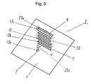
Also, as shown in the perspective view of Fig. 5, this antenna
can be configured in that the other end 13c of the first antenna
element 13 and one end 23a of the second antenna element 23 are
connected to each other at the top via conductive plate 8 made
from copper material or the like. In such a configuration, since
load capacitance is arisen between the ground plane 1 and the
conductive plate 8, the antenna impedance at the feeding point
2 can be further enhanced. Therefore, for example, in the case
of an antenna of 900MHz band used for cellular phones, mechanical
height h can be lowered from 23mm to 18mm, and further, the antenna
can be reduced in size.
-
Moreover, since the resonance frequency of the antenna can
be easily adjusted by, for example, notching a part 8a of the
conductive plate 8, it is also possible to easily obtain the
desired resonance frequency.
-
Also, Fig. 6 is a plan view showing a method of manufacturing
an antenna. As shown in Fig. 6, the first antenna element 13,
the second antenna element 23, and the conductive plate 8 are
all over connected to hoop frame 51 by connecting portion 51a.
In this way, each part of the antenna is simultaneously formed
into plate shape by pressing or etching a flat plate such as
plate copper material. After that, the connecting portion 51a
are cut off by means of a press or the like, followed by integrally
bending the first antenna element 13, the second antenna element
23, and the conductive plate 8 by pressing. Further, with these
parts integrally three-dimensionally formed with resin or the
like, an antenna of the present invention can be realized as
shown in Fig. 5.
-
That is, since the first and second antenna elements are
made from plate copper material, the antenna elements can be
easily formed by pressing or etching. Further, it is possible
to obtain more reliable antenna characteristics.
(Second preferred embodiment)
-
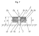
Fig. 7 is a side view of an antenna in the second preferred
embodiment of the present invention. As shown in the figure,
the antenna of the second preferred embodiment is configured
in that the first antenna element 13 and the second antenna element
23 made from linear or plate copper material are formed in
line-symmetrical relation with each other to the Z line on same
plain surface.
-
In the above configuration, during signal transmission,
high-frequency signals are supplied from the feeding point 2
at the center of ground plane 1 to the first antenna element
13 and the second antenna element 23. Then, high-frequency
current (i13) of the first antenna element 13 and high-frequency
current (i23) of the second antenna element 23 are excited in
same phase, and electromagnetic wave is emitted into the air.
Also, in the case of signal reception, the operations are reversed
to receive the signals.
-
According to the second preferred embodiment, since the first
antenna element 13 and the second antenna element 23 are formed
in line-symmetrical relation with each other on same plain
surface, it is possible to obtain same antenna characteristics
as in the first preferred embodiment. Further, the antenna
element can be reduced in thickness, and it is possible to obtain
an antenna which can be installed on a glass surface of a vehicle.
-
Incidentally, same effects can be obtained by arranging the
disposal relation between the first antenna element 13 and the
second antenna element 23 in nearly V-shape, nearly L-shape,
or curved surface shape.
-
Also, described above is a configuration such that the
intermediate portions of the first antenna element 13 and the
second antenna element 23, conductors such as linear or plate
copper material, are folded by a plurality of times in nearly
U-shape with sharp corner. However, the intermediate portions
of both antenna elements 13, 23 are, for example, preferable
to be nearly V-shaped as in Fig. 8 (a) or U-shaped with round
corner as in Fig. 8 (b), and further, spirally shaped or the
like (not shown). Similar effects can be obtained if configured
in that the first and second antenna elements are folded by a
plurality of times to excite the high-frequency current in same
phase.
-
Further, described above is an example such that the first
antenna element 13 and the second antenna element 23 are made
by machining linear or plate copper material or the like. However,
as shown in Fig. 8 (a), (b), same as in forming ground plane
11 by using copper foil of printed circuit board 5, it is also
preferable to realize both antenna elements 13, 23 by forming
the first antenna element 13 and the second antenna element 23
by etching the copper foil of copper-coated ceramic board or
printed circuit board 6 as a substrate into a desired shape.
-
Thus, by forming the first and second antenna elements 13,
23 being foil-like by etching or the like, it is possible to
realize an antenna which is less in dimensional alteration and
having reliable characteristics.
-
Also, as shown in Fig. 9, similar effects can be obtained
by forming the intermediate portions of the first antenna element
13 and the second antenna element 23 in laterally parallel
relation to the ground plane 1.
-
Also, mechanical height h of the first and second antenna
elements 13, 23 is allowable to be other than the height of 1/15
wavelength. It is preferable to properly select space h2 and
width w so that each line length of the antenna elements
corresponds to the folded shape of the length of 5/4 wavelength
(that is, each line length of which the antenna operates in 1/4
wavelength mode). Same effects can also be obtained in this
way.
-
Further, it is possible to use a configuration as shown in
Fig. 10. That is, antenna element 33 with its one end connected
to the ground plane 1 is disposed on the opposing surface of
either one or both of the first antenna element 13 and the second
antenna element 23. The intermediate portion of the antenna
element 33 is same in shape as the first antenna element 13 and
is folded by a plurality of times with the other end opened.
That is, in Fig. 10, there are further provided one or a plurality
of parasitic antenna elements 33, and each of the parasitic
antenna elements 33 is arranged in parallel relation to the
surface where the first antenna element 13 and the second antenna
element 23 are disposed. In such a configuration,
high-frequency current flows in same phase to the antenna element
33aswell, enhancing the excitation, and it is possible to further
expand the band of the antenna.
-
As described above, according to the present invention, the
antenna element can be lowered in height and it is possible to
obtain a small size antenna.