EP1439326A1 - Rack-and-pinion gear mechanism - Google Patents
Rack-and-pinion gear mechanism Download PDFInfo
- Publication number
- EP1439326A1 EP1439326A1 EP01976832A EP01976832A EP1439326A1 EP 1439326 A1 EP1439326 A1 EP 1439326A1 EP 01976832 A EP01976832 A EP 01976832A EP 01976832 A EP01976832 A EP 01976832A EP 1439326 A1 EP1439326 A1 EP 1439326A1
- Authority
- EP
- European Patent Office
- Prior art keywords
- rack
- pinion gear
- tooth
- engagement
- gear mechanism
- Prior art date
- Legal status (The legal status is an assumption and is not a legal conclusion. Google has not performed a legal analysis and makes no representation as to the accuracy of the status listed.)
- Withdrawn
Links
Images




Classifications
-
- F—MECHANICAL ENGINEERING; LIGHTING; HEATING; WEAPONS; BLASTING
- F16—ENGINEERING ELEMENTS AND UNITS; GENERAL MEASURES FOR PRODUCING AND MAINTAINING EFFECTIVE FUNCTIONING OF MACHINES OR INSTALLATIONS; THERMAL INSULATION IN GENERAL
- F16H—GEARING
- F16H19/00—Gearings comprising essentially only toothed gears or friction members and not capable of conveying indefinitely-continuing rotary motion
- F16H19/02—Gearings comprising essentially only toothed gears or friction members and not capable of conveying indefinitely-continuing rotary motion for interconverting rotary or oscillating motion and reciprocating motion
- F16H19/04—Gearings comprising essentially only toothed gears or friction members and not capable of conveying indefinitely-continuing rotary motion for interconverting rotary or oscillating motion and reciprocating motion comprising a rack
-
- F—MECHANICAL ENGINEERING; LIGHTING; HEATING; WEAPONS; BLASTING
- F16—ENGINEERING ELEMENTS AND UNITS; GENERAL MEASURES FOR PRODUCING AND MAINTAINING EFFECTIVE FUNCTIONING OF MACHINES OR INSTALLATIONS; THERMAL INSULATION IN GENERAL
- F16H—GEARING
- F16H1/00—Toothed gearings for conveying rotary motion
- F16H1/02—Toothed gearings for conveying rotary motion without gears having orbital motion
- F16H1/04—Toothed gearings for conveying rotary motion without gears having orbital motion involving only two intermeshing members
- F16H1/12—Toothed gearings for conveying rotary motion without gears having orbital motion involving only two intermeshing members with non-parallel axes
- F16H1/16—Toothed gearings for conveying rotary motion without gears having orbital motion involving only two intermeshing members with non-parallel axes comprising worm and worm-wheel
-
- F—MECHANICAL ENGINEERING; LIGHTING; HEATING; WEAPONS; BLASTING
- F16—ENGINEERING ELEMENTS AND UNITS; GENERAL MEASURES FOR PRODUCING AND MAINTAINING EFFECTIVE FUNCTIONING OF MACHINES OR INSTALLATIONS; THERMAL INSULATION IN GENERAL
- F16H—GEARING
- F16H1/00—Toothed gearings for conveying rotary motion
- F16H1/02—Toothed gearings for conveying rotary motion without gears having orbital motion
- F16H1/20—Toothed gearings for conveying rotary motion without gears having orbital motion involving more than two intermeshing members
-
- F—MECHANICAL ENGINEERING; LIGHTING; HEATING; WEAPONS; BLASTING
- F16—ENGINEERING ELEMENTS AND UNITS; GENERAL MEASURES FOR PRODUCING AND MAINTAINING EFFECTIVE FUNCTIONING OF MACHINES OR INSTALLATIONS; THERMAL INSULATION IN GENERAL
- F16H—GEARING
- F16H19/00—Gearings comprising essentially only toothed gears or friction members and not capable of conveying indefinitely-continuing rotary motion
- F16H19/02—Gearings comprising essentially only toothed gears or friction members and not capable of conveying indefinitely-continuing rotary motion for interconverting rotary or oscillating motion and reciprocating motion
- F16H19/04—Gearings comprising essentially only toothed gears or friction members and not capable of conveying indefinitely-continuing rotary motion for interconverting rotary or oscillating motion and reciprocating motion comprising a rack
- F16H2019/046—Facilitating the engagement or stopping of racks
-
- G—PHYSICS
- G11—INFORMATION STORAGE
- G11B—INFORMATION STORAGE BASED ON RELATIVE MOVEMENT BETWEEN RECORD CARRIER AND TRANSDUCER
- G11B17/00—Guiding record carriers not specifically of filamentary or web form, or of supports therefor
- G11B17/02—Details
- G11B17/04—Feeding or guiding single record carrier to or from transducer unit
-
- Y—GENERAL TAGGING OF NEW TECHNOLOGICAL DEVELOPMENTS; GENERAL TAGGING OF CROSS-SECTIONAL TECHNOLOGIES SPANNING OVER SEVERAL SECTIONS OF THE IPC; TECHNICAL SUBJECTS COVERED BY FORMER USPC CROSS-REFERENCE ART COLLECTIONS [XRACs] AND DIGESTS
- Y10—TECHNICAL SUBJECTS COVERED BY FORMER USPC
- Y10T—TECHNICAL SUBJECTS COVERED BY FORMER US CLASSIFICATION
- Y10T74/00—Machine element or mechanism
- Y10T74/18—Mechanical movements
- Y10T74/18568—Reciprocating or oscillating to or from alternating rotary
- Y10T74/188—Reciprocating or oscillating to or from alternating rotary including spur gear
- Y10T74/18808—Reciprocating or oscillating to or from alternating rotary including spur gear with rack
-
- Y—GENERAL TAGGING OF NEW TECHNOLOGICAL DEVELOPMENTS; GENERAL TAGGING OF CROSS-SECTIONAL TECHNOLOGIES SPANNING OVER SEVERAL SECTIONS OF THE IPC; TECHNICAL SUBJECTS COVERED BY FORMER USPC CROSS-REFERENCE ART COLLECTIONS [XRACs] AND DIGESTS
- Y10—TECHNICAL SUBJECTS COVERED BY FORMER USPC
- Y10T—TECHNICAL SUBJECTS COVERED BY FORMER US CLASSIFICATION
- Y10T74/00—Machine element or mechanism
- Y10T74/19—Gearing
- Y10T74/19642—Directly cooperating gears
- Y10T74/1967—Rack and pinion
Definitions
- the present invention relates to a rack and pinion gear mechanism by which an engagement and its releasing can be performed between a rack and a pinion gear.
- Fig. 1 is a front view to show a constitution of the rack and pinion gear mechanism in the prior art technology which is disclosed in the above mentioned Laid Open patent gazette.
- a reference numeral 1 designates a main body rack
- 2 designates a conveying means to carry pinion series 3A, 3B, 3C and the like.
- the main body rack 1 is fixed on the main body flame by pins 5 and 6.
- a pinion introducing side (which is shown as right side in Fig. 1) of the main body rack 1
- a introducing segment rack 7 is arranged capable of rocking in vertical direction around a pin 6 as an axis contacting with the main body rack 1.
- a pitch line 11 in tooth depth direction of the introducing segment rack 7 and a pitch line 13 in tooth depth direction of the main body 1 are matched.
- the introducing segment rack 7 is arranged in relation to the main body rack 1 such that a gear pitch 9 of the introducing segment rack 7 at the junction point 8 is made aligned with a gear pitch 10 of the main body rack 1.
- An end portion 7B of the pinion introducing side of introducing segment rack 7 is held so that the pitch line 11 in tooth depth direction becomes at least lower than the pitch line 13 of tooth depth direction of the main body rack 1 in a predetermined amount 12.
- the above mentioned amount 12 is maintained by means that a block 15 which is built as one body in the introducing segment rack 7 is pushed against a stop pin 14 by a boost up force of spring 16.
- a distance 20 between the stop pin 14 and an end surface of the end portion 7B of pinion introducing side of the introducing segment rack 7 is set less than one half of the gear pitch.
- the spring 17 is an elastic member to press the introducing segment rack 7 to the main body rack 1. A force generated in a tooth surfaces when the introducing segment rack 7 and the pinion 3B and the like are engaged, can be absorbed by a displacement and its return in longitudinal direction of the introducing segment rack 7.
- the present invention has been made to solve the above described problem and it is an object of the invention to provide a rack and pinion gear mechanism by which the disadvantages caused by confliction of the tooth points can be prevented with a simple constitution.
- the rack and pinion gear mechanism in accordance with the present invention includes a rack forming member having a rack; a pinion gear which engages releasably with the rack of rack forming member; and an elastic member which contacts with one portion of said rack forming member, which is located opposite side to a tooth of the rack that contacts firstly with a tooth of said pinion gear and is deformed by an elastic deformation corresponding to a displacement of the rack forming member by a confliction of tooth points.
- the rack and pinion gear mechanism in accordance with the present invention is arranged such that the elastic member contacts with the one portion of rack forming member at just before and just after beginning of the engagement between the rack and the pinion gear, and the elastic member is apart from the rack forming member when the engagement is continued.
- the rack and pinion gear mechanism in accordance with the present invention further includes a positioning means to fix the elastic member in a cantilever manner to define a positioning of free end of the elastic member in height.
- the rack and pinion gear mechanism in accordance with the present invention is arranged such that a tooth of the rack which firstly contacts with a tooth of the pinion gear at the engagement with the pinion gear, is made lower than the other teeth in its height of tooth top.
- a rack and pinion gear mechanism in accordance with embodiment 1 of the present invention can be applied to, for example, a driving a disk carrying mechanism (not shown in the drawings) which holds a compact disk (hereinafter it is refereed to as "CD") to carry it to a predetermined position and at the same time evacuates from a projection surface of CD when it is in a reproducing state in a CD driving device (not shown in the drawings) by which the reproducing of optical recording media such as CD is performed, however, this embodiment 1 is only an example and the present invention is not limited only to this embodiment 1.
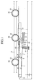
- Fig. 2 is a perspective view to show a rack and pinion gear mechanism in accordance with embodiment 1 of the present invention in a state just before an engagement of tooth points occurs
- Fig. 3 is a front view of the rack and pinion gear mechanism shown in Fig. 2.
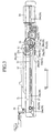
- Fig. 4 is an enlarged perspective view to show a relevant part of the rack and pinion gear mechanism shown in Fig. 2
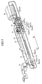
- Fig. 5 is a perspective view to show the rack and pinion gear mechanism shown in Fig. 2 to Fig. 4 in a state just after an engagement has been begun without an occurrence of the confliction of tooth points.
- Fig. 6 is a perspective view to show a state that the engagement is proceeded from the state the engagement has been begun as shown in Fig. 5, and Fig.
- FIG. 7 is a front view to show an action of the rack when it is in the engagement shown in Fig. 5 and Fig. 6.
- Fig. 8 is a perspective view to show the rack and pinion gear mechanism shown in Fig. 2 to Fig. 4 in a state just after an engagement has been begun with an occurrence of the confliction of tooth points
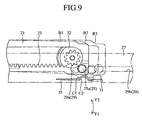
- Fig. 9 is a front view to show an action of the rack when it is in a state of the engagement with the confliction of tooth points.
- an end portion of rack which is nearer to a pinion gear is called as a "front end” and an end portion of the rack which is farther to the pinion gear is called as a "back end” as far as it is not especially refereed.
- a reference numeral 21 designates a rack plate which has a long plate shape.
- a continuos length of opening portion 22 is made in a position which is near to the pinion gear that will be described later.
- a width of this opening portion 22 is made wider than an outer diameter of the pinion gear (diameter of addendum circle) that will be described later.
- a rack 23 is made which is composed of an arrangement of teeth that is disposed along a straight line.
- the rack is made such that height of a first tooth 23a of the rack 23 (tooth height) is lower than the other teeth in order to absorb a confliction of tooth points between the rack 23 and a pinion gear that will be described later.
- a back side guiding pin 24 and a front side guiding pin 25 which are separated each other along its long direction, are disposed at a surface opposing to a mounting table that will be described later.
- the back side guiding pin24 is disposed at a back position which is apart from the opening portion 22, and the front side guiding pin 25 is disposed at a front position which is near to the opening portion 22.
- These back side guiding pin 24 and front side guiding pin 25 are respectively composed of a head portion 24a and 25a which have a large outer diameter and a foot portion 24b and 25b (not shown) which have a smaller outer diameter than the head portions.
- a sliding portion 26 is formed, which slides and contacts with an elastic member that will be described later.
- This sliding portion 26 is composed of a sliding surface 26a which receives a sliding by the elastic member that will be described later, a front curved surface 26b which is formed in front of the sliding surface 26a to absorb a mechanical shock by a contact with the elastic member that will be described later when the rack plate 21 moves forward, and a back curved surface 26c which is formed at the back of the above mentioned sliding surface 26a to absorb the mechanical shock by the contact with the elastic member that will be described later when the rack plate 21 moves backward.
- a reference numeral 27 designates the mounting table having a long plate shape, and the mounting table is formed on a chassis (not shown) of the above mentioned CD driving device (not shown).
- the mounting table 27 has two guiding grooves which are a back side guiding groove 28 and a front side guiding groove 29 and they are extending along their long direction and separated each other along the same direction.
- the back side guiding groove 28 is mainly composed of a circular groove portion 28a through which head portion 24a of the back side guiding pin 24 can be inserted, and a straight groove portion 28b which is formed continuously to the circular groove portion 28a having a width that is defined within a range between outer diameters of the head portion 24a and the foot portion 24b of the back side guiding pin 24.
- the front side guiding groove 29 is mainly composed of a circular groove portion 29a through which head portion 25a of the front side guiding pin 25 can be inserted, and a straight groove portion 29b which is formed continuously to the circular groove portion 29a having a width that is defined within a range between outer diameters of the head portion 25a and the foot portion 25b of the front side guiding pin 25.
- the straight groove portion 29b there is provided a concave portion 30 at a position where the circular groove portion 29a is adjoining.
- the concave portion 30 is composed of a falling portion 30a which falls from the straight groove portion 29b, a flat portion 30b which is formed continuously to a lowest portion of the flat portion 30a and is parallel to the straight groove portion 29b, and a rising portion 30c which is formed continuously to the flat portion 30b and rises to the straight groove portion 29b.
- a distance between an upper edge portion of the straight groove portion 29b and the flat portion 30b of the concave portion 30 is defined smaller than the outer diameter of head portion 25a of the front side guiding pin 25.
- a concave portion 31 is provided in a vicinity of the above mentioned concave portion 30 to perform a height adjusting of the elastic member that will be described later.
- a pinion gear 32 is rotatably fixed to be made enable to engage with the rack 23 of rack plate 21.
- a driving motor 34 to transfer a driving force through a series of idler gears 33 to the pinion gear 32.
- a leaf spring (elastic member) 35 is attached in a cantilever manner.
- This leaf spring 35 is composed of a base portion 35b which has a screw hole 35a for a fixing screw (not shown) to fasten the leaf spring 35 onto the mounting table 27, a protruding portion 35c having an inverted V shape which is formed in a free end side that is extending forward from the base portion 35b, and a engaging portion 35d which is formed continuously to the protruding portion 35c to engage with the concave portion 31 of mounting table 27.
- the leaf spring 35 is supported at the base portion 35b by the mounting table 27 and it is set such that the protruding portion 35c urges the rack plate 21 always upward.
- a reference numeral 36 designates a trigger.
- the trigger 36 pushes a back end portion of the rack plate 21 forward to engage the rack 23 and the pinion gear 32, thereby it encourages a beginning of action for a rack and pinion gear mechanism which is constituted as above described.
- the back side guiding pin 24 and the front side guiding pin 25 of rack plate 21 are supported in a state that they are inserted into the circular groove portions 28a and 29a of back side guiding groove 28 and front side guiding groove 29.
- a reference symbol A1 in Fig. 7 designates a posture and a position of the rack plate 21 just before the engagement corresponding to Fig. 2 to Fig. 4
- A2 designates a posture and a position of the rack plate 21 at the engagement corresponding to Fig. 5
- A3 designates a posture and a position of the rack plate 21 just after the engagement corresponding to Fig. 6.
- the confliction of tooth points occurred, it can be absorbed by means that the leaf spring is deformed by an elastic deformation caused by a force generated by the confliction of tooth points to rotate the rack plate 21 along a direction shown by an arrow Y1 around the back side guiding pin 24 as a center.
- the rack plate 21 in a state of rotation is reset to an original position along a direction shown by an arrow Y2 by an elastic reset of the leaf spring 35.
- a reference symbol B1 in Fig. 9 designates a posture and a position of the rack plate 21 just before the confliction of tooth points occurs
- B2 designates a posture and a position of the rack plate 21 at the confliction of tooth points corresponding to Fig. 8
- B3 designates a posture and a position of the rack plate 21 just after the confliction of tooth points occurs
- a reference symbol C1 in Fig. 9 designates a posture and a position of the leaf spring 35 when the rack plate 21 is in a posture and position of B1 and B3
- C2 designates a posture and a position of the leaf spring 35 when the rack plate 21 is in a posture and position of B2.
- the driving force by the driving motor 34 is transferred to the pinion gear 32 in order to reversely rotate the pinion gear 32 when the rack plate is returned backward along the direction that arrow X2 shows.
- the rack plate 21 is returned backward, thereby the engagement between the rack 23 and the pinion gear 32 is released at the first tooth 23a of rack 23 side finally, then a backward movement of the rack plate 21 is stopped.
- the posture and the height of rack plate 21 are kept because the sliding portion 26 of rack plate 21 is contacted with the protruding portion 35 c of leaf spring 35 ant it is supported, only when the front side guiding pin 25 passes over the concave portion 30 of front guiding groove 29. Accordingly the posture and the height of rack plate 21 are always kept when the rack plate 21 moves backward.
- the gear mechanism is constituted such that the leaf spring 35 is provided as the elastic member, though it has merely a simple constitution in comparison with the gear mechanism in the prior art technology, the leaf spring 35 can be deformed by the elastic deformation corresponding to a displacement (rotating movement) of the rack plate 21 having the rack 23 when the confliction of tooth points occurs at very beginning of the engagement between the rack 23 and the pinion gear 32, an effect is produced that an occurrence of disadvantages such as a damage of driving motor, a breakage of teeth and the like caused by the confliction of tooth points can be avoided.
- an effect is produced that the rack plate 21 which is shifted with an elastic deformation of the leaf spring 35 in order to absorb the confliction of tooth points, can be surely reset at the original position utilizing an elasticity of the leaf spring 35 because the leaf spring 35 is arranged to be apart from the rack plate 21 just before and after a beginning of the engagement between the rack 23 and the pinion gear 32, and at the same time the contact between the leaf spring 35 and the rack plate 21 can be avoided to suppress the sliding load as low as possible when the rack 23 and the pinion gear 32 are engaged each other.
- a height of the protruding portion 35c can be adjusted in order that the protruding portion 35c is slightly contacted with the sliding portion 26 of rack plate 21 just before and just after beginning of the engagement because it is constituted that the concave portion 31 is formed on the mounting table 27 as a positioning means by which the leaf spring 35 is fixed in a cantilever manner and defines a positioning of the protruding portion 35c of free end side of the leaf spring 35 in height.
- an effect is produced that occurrence of the confliction of tooth points can be decreased and the smooth engagement can be attained because a height of the first tooth 23a of rack 23 is made lower than the other teeth of the rack 23, which contacts firstly with a tooth of the pinion gear 32 when the engagement with the pinion gear 32 is achieved.
- the present invention provides the rack and pinion gear mechanism by which the engagement and its release are achieved between the rack and the pinion gear, and the present invention is applicable, for example, in a CD driving device for driving of disk conveying mechanism which holds CD to carry to a predetermined position, and at the same time evacuates from a projection surface of CD when it is in a reproducing state.
Landscapes
- Engineering & Computer Science (AREA)
- General Engineering & Computer Science (AREA)
- Mechanical Engineering (AREA)
- Transmission Devices (AREA)
- Feeding And Guiding Record Carriers (AREA)
- Moving Of Heads (AREA)
Abstract
A rack and pinion gear mechanism includes a rack forming
member 21 having a rack 23; a pinion gear 32 which engages
releasably with the rack of rack forming member; and an elastic
member 35 which contacts with one portion of the rack forming
member and is deformed by an elastic deformation corresponding
to a displacement of the rack forming member by a confliction
of tooth points, the one portion is located opposite side to
a tooth 23a of the rack that contacts firstly with a tooth of
the pinion gear. The elastic member 35 contacts with the one
portion of rack forming member 21 at just before and just after
beginning of the engagement between the rack 23 and the pinion
gear 32, and the elastic member 35 is apart from the rack forming
member when the engagement is continued. The rack and pinion
gear mechanism further includes a positioning means 31 to fix
the elastic member 35 in a cantilever manner to define a
positioning of a free end of the elastic member in height. The
tooth (23a) of the rack which firstly contacts with a tooth of
the pinion gear 32 at the engagement with the pinion gear, is
made lower than the other teeth in its height of tooth top.
Description
The present invention relates to a rack and pinion gear
mechanism by which an engagement and its releasing can be
performed between a rack and a pinion gear.
As a rack and pinion gear mechanism in the prior art
technology, it is well known, for example, that is disclosed
in Japanese Laid Open Patent Sho 63-176857 patent gazette.
Fig. 1 is a front view to show a constitution of the rack
and pinion gear mechanism in the prior art technology which is
disclosed in the above mentioned Laid Open patent gazette. In
the drawing a reference numeral 1 designates a main body rack,
2 designates a conveying means to carry pinion series 3A, 3B,
3C and the like. The main body rack 1 is fixed on the main body
flame by pins 5 and 6. In a pinion introducing side (which is
shown as right side in Fig. 1) of the main body rack 1, a
introducing segment rack 7 is arranged capable of rocking in
vertical direction around a pin 6 as an axis contacting with
the main body rack 1. At a junction point 8 of an end portion
of the main body rack 1 and an end portion 7A of the introducing
segment rack 7, a pitch line 11 in tooth depth direction of the
introducing segment rack 7 and a pitch line 13 in tooth depth
direction of the main body 1 are matched. And the introducing
segment rack 7 is arranged in relation to the main body rack
1 such that a gear pitch 9 of the introducing segment rack 7
at the junction point 8 is made aligned with a gear pitch 10
of the main body rack 1. An end portion 7B of the pinion
introducing side of introducing segment rack 7 is held so that
the pitch line 11 in tooth depth direction becomes at least lower
than the pitch line 13 of tooth depth direction of the main body
rack 1 in a predetermined amount 12. At this point the above
mentioned amount 12 is maintained by means that a block 15 which
is built as one body in the introducing segment rack 7 is pushed
against a stop pin 14 by a boost up force of spring 16.
And a distance 20 between the stop pin 14 and an end surface
of the end portion 7B of pinion introducing side of the
introducing segment rack 7 is set less than one half of the gear
pitch. The spring 17 is an elastic member to press the
introducing segment rack 7 to the main body rack 1. A force
generated in a tooth surfaces when the introducing segment rack
7 and the pinion 3B and the like are engaged, can be absorbed
by a displacement and its return in longitudinal direction of
the introducing segment rack 7.
Hereinafter operation of the mechanism will be explained.
When the pinion 3B, for example, usually comes from right
hand direction of the drawing and arrives on the introducing
segment rack 7, a tooth point of the pinion 3B and a tooth point
of the introducing segment rack 7 interfere together. At this
point the introducing segment rack 7 rocks downward around axis
of the pin 6 as a center to absorb the force generated at the
tooth points. By this movement disadvantages such as a
malfunction of the gear mechanism, a damage of driving motor,
a breakage of teeth and the like are prevented.
However in the rack and pinion gear mechanism in the prior
art technology there has been a problem that a constitution of
the gear mechanism is too complicated because a means to prevent
the disadvantages which is generated by a confliction of the
tooth points, is composed of the introducing segment rack 7 that
moves to a direction to release an engagement when the
confliction of tooth points occurs, the spring 16 that always
presses the introducing segment rack 7 upward to hold it at a
predetermined position and the spring 17 that urges the gears
in a direction for the engagement and makes the gears smoothly
engaged when the engagement is released.
The present invention has been made to solve the above
described problem and it is an object of the invention to provide
a rack and pinion gear mechanism by which the disadvantages
caused by confliction of the tooth points can be prevented with
a simple constitution.
The rack and pinion gear mechanism in accordance with the
present invention includes a rack forming member having a rack;
a pinion gear which engages releasably with the rack of rack
forming member; and an elastic member which contacts with one
portion of said rack forming member, which is located opposite
side to a tooth of the rack that contacts firstly with a tooth
of said pinion gear and is deformed by an elastic deformation
corresponding to a displacement of the rack forming member by
a confliction of tooth points. By this arrangement an effect
is produced that an occurrence of disadvantages such as a damage
of driving motor, a breakage of teeth and the like caused by
the confliction of tooth points can be avoided, though it has
merely a simple constitution in comparison with the gear
mechanism in the prior art technology, the elastic member can
be deformed by the elastic deformation corresponding to a
displacement of the rack forming member having the rack when
the confliction of tooth points occurs at very beginning of the
engagement.
The rack and pinion gear mechanism in accordance with the
present invention is arranged such that the elastic member
contacts with the one portion of rack forming member at just
before and just after beginning of the engagement between the
rack and the pinion gear, and the elastic member is apart from
the rack forming member when the engagement is continued. By
this arrangement an effect is produced that the rack forming
member can be surely reset utilizing an elasticity of the
elastic member when it need, and at the same time the contact
between the elastic member and the rack forming member can be
avoided to suppress the sliding load as low as possible when
it does not need.
The rack and pinion gear mechanism in accordance with the
present invention further includes a positioning means to fix
the elastic member in a cantilever manner to define a
positioning of free end of the elastic member in height. By
this arrangement an effect is produced that a decrease of
durability in operation can be avoidable because a height of
the elastic member can be adjusted in order that the elastic
member is slightly contacted with one portion of the rack
forming member just before and just after beginning of the
engagement, and the sliding load of elastic member against the
rack forming member can be suppressed as low as possible.
The rack and pinion gear mechanism in accordance with the
present invention is arranged such that a tooth of the rack which
firstly contacts with a tooth of the pinion gear at the
engagement with the pinion gear, is made lower than the other
teeth in its height of tooth top. By this arrangement an effect
is produced that occurrence of the confliction of tooth points
can be decreased and the smooth engagement can be attained.
For explaining the present invention in more detail, best
mode for carrying out the invention will be described
hereinafter with reference to the accompanied drawings.
A rack and pinion gear mechanism in accordance with
embodiment 1 of the present invention can be applied to, for
example, a driving a disk carrying mechanism (not shown in the
drawings) which holds a compact disk (hereinafter it is refereed
to as "CD") to carry it to a predetermined position and at the
same time evacuates from a projection surface of CD when it is
in a reproducing state in a CD driving device (not shown in the
drawings) by which the reproducing of optical recording media
such as CD is performed, however, this embodiment 1 is only an
example and the present invention is not limited only to this
embodiment 1.
Fig. 2 is a perspective view to show a rack and pinion gear
mechanism in accordance with embodiment 1 of the present
invention in a state just before an engagement of tooth points
occurs, and Fig. 3 is a front view of the rack and pinion gear
mechanism shown in Fig. 2. Fig. 4 is an enlarged perspective
view to show a relevant part of the rack and pinion gear mechanism
shown in Fig. 2, and Fig. 5 is a perspective view to show the
rack and pinion gear mechanism shown in Fig. 2 to Fig. 4 in a
state just after an engagement has been begun without an
occurrence of the confliction of tooth points. Fig. 6 is a
perspective view to show a state that the engagement is
proceeded from the state the engagement has been begun as shown
in Fig. 5, and Fig. 7 is a front view to show an action of the
rack when it is in the engagement shown in Fig. 5 and Fig. 6.
Fig. 8 is a perspective view to show the rack and pinion gear
mechanism shown in Fig. 2 to Fig. 4 in a state just after an
engagement has been begun with an occurrence of the confliction
of tooth points, and Fig. 9 is a front view to show an action
of the rack when it is in a state of the engagement with the
confliction of tooth points. At this point in the drawings an
end portion of rack which is nearer to a pinion gear is called
as a "front end" and an end portion of the rack which is farther
to the pinion gear is called as a "back end" as far as it is
not especially refereed.
In the drawings a reference numeral 21 designates a rack
plate which has a long plate shape. In an inside front of the
rack plate 21 a continuos length of opening portion 22 is made
in a position which is near to the pinion gear that will be
described later. A width of this opening portion 22 is made
wider than an outer diameter of the pinion gear (diameter of
addendum circle) that will be described later. In a under edge
portion of the opening portion 22 a rack 23 is made which is
composed of an arrangement of teeth that is disposed along a
straight line. In this embodiment 1, the rack is made such that
height of a first tooth 23a of the rack 23 (tooth height) is
lower than the other teeth in order to absorb a confliction of
tooth points between the rack 23 and a pinion gear that will
be described later.
In the rack plate constituted as described above, a back
side guiding pin 24 and a front side guiding pin 25 which are
separated each other along its long direction, are disposed at
a surface opposing to a mounting table that will be described
later. The back side guiding pin24 is disposed at a back
position which is apart from the opening portion 22, and the
front side guiding pin 25 is disposed at a front position which
is near to the opening portion 22. These back side guiding pin
24 and front side guiding pin 25 are respectively composed of
a head portion 24a and 25a which have a large outer diameter
and a foot portion 24b and 25b (not shown) which have a smaller
outer diameter than the head portions.
Also in a lower front portion of the rack plate 21, a sliding
portion 26 is formed, which slides and contacts with an elastic
member that will be described later. This sliding portion 26
is composed of a sliding surface 26a which receives a sliding
by the elastic member that will be described later, a front
curved surface 26b which is formed in front of the sliding
surface 26a to absorb a mechanical shock by a contact with the
elastic member that will be described later when the rack plate
21 moves forward, and a back curved surface 26c which is formed
at the back of the above mentioned sliding surface 26a to absorb
the mechanical shock by the contact with the elastic member that
will be described later when the rack plate 21 moves backward.
A reference numeral 27 designates the mounting table having
a long plate shape, and the mounting table is formed on a chassis
(not shown) of the above mentioned CD driving device (not
shown).
The mounting table 27 has two guiding grooves which are
a back side guiding groove 28 and a front side guiding groove
29 and they are extending along their long direction and
separated each other along the same direction. The back side
guiding groove 28 is mainly composed of a circular groove
portion 28a through which head portion 24a of the back side
guiding pin 24 can be inserted, and a straight groove portion
28b which is formed continuously to the circular groove portion
28a having a width that is defined within a range between outer
diameters of the head portion 24a and the foot portion 24b of
the back side guiding pin 24.
Also the front side guiding groove 29 is mainly composed
of a circular groove portion 29a through which head portion 25a
of the front side guiding pin 25 can be inserted, and a straight
groove portion 29b which is formed continuously to the circular
groove portion 29a having a width that is defined within a range
between outer diameters of the head portion 25a and the foot
portion 25b of the front side guiding pin 25. In this respect
in the straight groove portion 29b there is provided a concave
portion 30 at a position where the circular groove portion 29a
is adjoining. The concave portion 30 is composed of a falling
portion 30a which falls from the straight groove portion 29b,
a flat portion 30b which is formed continuously to a lowest
portion of the flat portion 30a and is parallel to the straight
groove portion 29b, and a rising portion 30c which is formed
continuously to the flat portion 30b and rises to the straight
groove portion 29b. At this point a distance between an upper
edge portion of the straight groove portion 29b and the flat
portion 30b of the concave portion 30 is defined smaller than
the outer diameter of head portion 25a of the front side guiding
pin 25.
At a lower edge portion of the mounting table 27, a concave
portion 31 is provided in a vicinity of the above mentioned
concave portion 30 to perform a height adjusting of the elastic
member that will be described later.
On the mounting table 27 constituted as described above,
a pinion gear 32 is rotatably fixed to be made enable to engage
with the rack 23 of rack plate 21. At the same time on the
mounting table 27 a driving motor 34 to transfer a driving force
through a series of idler gears 33 to the pinion gear 32.
Also on the mounting table 27 a leaf spring (elastic member)
35 is attached in a cantilever manner. This leaf spring 35 is
composed of a base portion 35b which has a screw hole 35a for
a fixing screw (not shown) to fasten the leaf spring 35 onto
the mounting table 27, a protruding portion 35c having an
inverted V shape which is formed in a free end side that is
extending forward from the base portion 35b, and a engaging
portion 35d which is formed continuously to the protruding
portion 35c to engage with the concave portion 31 of mounting
table 27. The leaf spring 35 is supported at the base portion
35b by the mounting table 27 and it is set such that the
protruding portion 35c urges the rack plate 21 always upward.
However, by means that the engaging portion 35d of the leaf
spring 35 is engaged with the concave portion 31 of mounting
table 27, a urging of 21 by the protruding portion 35c of leaf
spring 35 is regulated in a level that the rack plate 21 slightly
contacts with the protruding portion 35c and the rack plate 21
is slidable without any large load, thereby a height of the
protruding portion 35c is regulated. At the same time because
the back side guiding pin 24 and the front side guiding pin 25
are not pushed to respective upper edge portions of the back
side guiding groove 28 and the front side guiding groove 29,
respective large sliding loads to the back side guiding pin 24
and front side guiding pin 25 can be avoided.
A reference numeral 36 designates a trigger. When at a
timing that, for example, a CD is carried to a reproducing
position or to a exchanging position, a command is initiated
from a CPU (not shown), the trigger 36 pushes a back end portion
of the rack plate 21 forward to engage the rack 23 and the pinion
gear 32, thereby it encourages a beginning of action for a rack
and pinion gear mechanism which is constituted as above
described.
Hereinafter an operation of the mechanism will be
explained.
At first before an operation is initiated, the back side
guiding pin 24 and the front side guiding pin 25 of rack plate
21 are supported in a state that they are inserted into the
circular groove portions 28a and 29a of back side guiding groove
28 and front side guiding groove 29.
Next as shown in Fig. 2 to Fig. 4, when at a timing, for
example, CD is carried to a reproducing position or to a
exchanging position, a command is initiated from the CPU (not
shown) , the trigger 36 pushes back end portion of the rack plate
21 forward. After the trigger 36 pushes the rack plate 21, the
driving motor 34 begins a driving by a command from the CPU (not
shown) as well, the driving force is transferred through the
series of idler gears 33 to begin a rotation of the pinion gear
32. When the rack plate 21 begins to go forward along an arrow
X1 direction by the above mentioned pushing of trigger 36, a
first tooth 23a of the rack 23 and the pinion gear 32 begins
to contact. In this respect by this embodiment 1 of the present
invention because the tooth height of the first tooth 23a of
rack 23 is made lower than other teeth of the rack 23, the
confliction of tooth points can be reduced as much as possible
thereby a smooth engagement can be realized.
By this arrangement, the confliction of tooth points is
not generated usually in this embodiment between the rack 23
and the pinion gear 32. In this case respective teeth tops are
deeply inserted to respective root of teeth, a smooth engagement
is achieved. By this engagement the rack plate 21 is carried
forward along the direction of arrow X1, and the back side
guiding pin 24 and the front side guiding pin 25 are guided along
the back side guiding groove 28 and the front side 29. At just
before and just after beginning of the engagement, because the
protruding portion 35c of leaf spring 35 supports the rack plate
21 with sliding and contacting onto the sliding portion 26, the
front side guiding pin 25 can pass over the concave portion 30
of front side guiding groove 29 and arrives at the straight
groove portion 29b. Because the back side guiding pin 24
arrives directly at the straight groove portion 28b from the
circular groove portion 28a, a height of whole rack plate 21
is not changed at before and after of the engagement and constant
always.
In this respect a reference symbol A1 in Fig. 7 designates
a posture and a position of the rack plate 21 just before the
engagement corresponding to Fig. 2 to Fig. 4, A2 designates
a posture and a position of the rack plate 21 at the engagement
corresponding to Fig. 5, and A3 designates a posture and a
position of the rack plate 21 just after the engagement
corresponding to Fig. 6.
If by any possibility the confliction of tooth points
occurred, it can be absorbed by means that the leaf spring is
deformed by an elastic deformation caused by a force generated
by the confliction of tooth points to rotate the rack plate 21
along a direction shown by an arrow Y1 around the back side
guiding pin 24 as a center. By this arrangement malfunction
and the like by the confliction of tooth points is avoided. Just
after the absorption of occurrence of confliction, the rack
plate 21 in a state of rotation is reset to an original position
along a direction shown by an arrow Y2 by an elastic reset of
the leaf spring 35. By this arrangement the respective teeth
tops are deeply inserted to respective root of teeth, thereby
the smooth engagement is achieved.
In a state after the rack plate 21 is reset, the protruding
portion 35c of leaf spring 35 moves away from sliding portion
26 of the rack plate 21, and the back side guiding pin 24 and
the front side guiding pin 25 are guided only by the straight
groove portion 28b of back side guiding groove 28 and the
straight groove portion 29b of front side guiding groove 29.
In this respect a reference symbol B1 in Fig. 9 designates
a posture and a position of the rack plate 21 just before the
confliction of tooth points occurs, B2 designates a posture and
a position of the rack plate 21 at the confliction of tooth points
corresponding to Fig. 8, and B3 designates a posture and a
position of the rack plate 21 just after the confliction of tooth
points occurs. A reference symbol C1 in Fig. 9 designates a
posture and a position of the leaf spring 35 when the rack plate
21 is in a posture and position of B1 and B3, C2 designates a
posture and a position of the leaf spring 35 when the rack plate
21 is in a posture and position of B2.
As above described, in any cases when the confliction of
tooth points occurs or does not occur, the driving force by the
driving motor 34 is transferred to the pinion gear 32 in order
to reversely rotate the pinion gear 32 when the rack plate is
returned backward along the direction that arrow X2 shows. By
this action the rack plate 21 is returned backward, thereby the
engagement between the rack 23 and the pinion gear 32 is released
at the first tooth 23a of rack 23 side finally, then a backward
movement of the rack plate 21 is stopped. As above described
when the rack plate 21 is moved backward, a posture and a height
of the rack plate 21 are kept from a beginning of backward
movement till the pinion gear 32 arrives at the first tooth 23a
of rack 23 because the back side guiding pin 24 and the front
side guiding pin 25 are guided only by the straight groove
portion 28b of the back side guiding groove 28 and by the straight
groove portion 29b of the front side guiding groove 29. And
at a time point from just before to just after the pinion gear
32 arrives at the first tooth 23a of the rack 23, the posture
and the height of rack plate 21 are kept because the sliding
portion 26 of rack plate 21 is contacted with the protruding
portion 35 c of leaf spring 35 ant it is supported, only when
the front side guiding pin 25 passes over the concave portion
30 of front guiding groove 29. Accordingly the posture and the
height of rack plate 21 are always kept when the rack plate 21
moves backward.
As above described, in accordance with embodiment 1 of
the present invention because the gear mechanism is constituted
such that the leaf spring 35 is provided as the elastic member,
though it has merely a simple constitution in comparison with
the gear mechanism in the prior art technology, the leaf spring
35 can be deformed by the elastic deformation corresponding to
a displacement (rotating movement) of the rack plate 21 having
the rack 23 when the confliction of tooth points occurs at very
beginning of the engagement between the rack 23 and the pinion
gear 32, an effect is produced that an occurrence of
disadvantages such as a damage of driving motor, a breakage of
teeth and the like caused by the confliction of tooth points
can be avoided.
In accordance with embodiment 1 of the present invention
an effect is produced that the rack plate 21 which is shifted
with an elastic deformation of the leaf spring 35 in order to
absorb the confliction of tooth points, can be surely reset at
the original position utilizing an elasticity of the leaf spring
35 because the leaf spring 35 is arranged to be apart from the
rack plate 21 just before and after a beginning of the engagement
between the rack 23 and the pinion gear 32, and at the same time
the contact between the leaf spring 35 and the rack plate 21
can be avoided to suppress the sliding load as low as possible
when the rack 23 and the pinion gear 32 are engaged each other.
In accordance with embodiment 1 of the present invention
a height of the protruding portion 35c can be adjusted in order
that the protruding portion 35c is slightly contacted with the
sliding portion 26 of rack plate 21 just before and just after
beginning of the engagement because it is constituted that the
concave portion 31 is formed on the mounting table 27 as a
positioning means by which the leaf spring 35 is fixed in a
cantilever manner and defines a positioning of the protruding
portion 35c of free end side of the leaf spring 35 in height.
By this arrangement an effect is produced that a decrease of
durability in operation can be avoidable because the sliding
load of protruding portion 35c against the rack plate 21 can
be suppressed as low as possible.
In accordance with embodiment 1 of the present invention
an effect is produced that occurrence of the confliction of
tooth points can be decreased and the smooth engagement can be
attained because a height of the first tooth 23a of rack 23 is
made lower than the other teeth of the rack 23, which contacts
firstly with a tooth of the pinion gear 32 when the engagement
with the pinion gear 32 is achieved.
As set forth above, the present invention provides the
rack and pinion gear mechanism by which the engagement and its
release are achieved between the rack and the pinion gear, and
the present invention is applicable, for example, in a CD
driving device for driving of disk conveying mechanism which
holds CD to carry to a predetermined position, and at the same
time evacuates from a projection surface of CD when it is in
a reproducing state.
Claims (4)
- A rack and pinion gear mechanism comprising:a rack forming member (21) having a rack (23);a pinion gear (32) which engages releasably with said rack of rack forming member; andan elastic member (35) which contacts with one portion of said rack forming member, which is located opposite side to a tooth (23a) of the rack that contacts firstly with a tooth of said pinion gear and is deformed by an elastic deformation corresponding to a displacement of the rack forming member by a confliction of tooth points.
- The rack and pinion gear mechanism according to claim 1 characterized by that said elastic member (35) contacts with the one portion of rack forming member (21) at just before and just after beginning of the engagement between the rack (23) and the pinion gear (32) , and the elastic member is apart from the rack forming member when the engagement is continued.
- The rack and pinion gear mechanism according to claim 2 characterized by further comprising a positioning means (31) to fix the elastic member (35) in a cantilever manner to define a positioning of free end of the elastic member in height.
- The rack and pinion gear mechanism according to claim 1 characterized by that a tooth (23a) of the rack which firstly contacts with a tooth of said pinion gear (32) at the engagement with the pinion gear, is made lower than the other teeth in its height of tooth top.
Applications Claiming Priority (1)
| Application Number | Priority Date | Filing Date | Title |
|---|---|---|---|
| PCT/JP2001/009351 WO2003036135A1 (en) | 2001-10-24 | 2001-10-24 | Rack-and-pinion gear mechanism |
Publications (2)
| Publication Number | Publication Date |
|---|---|
| EP1439326A1 true EP1439326A1 (en) | 2004-07-21 |
| EP1439326A4 EP1439326A4 (en) | 2008-09-03 |
Family
ID=11737868
Family Applications (1)
| Application Number | Title | Priority Date | Filing Date |
|---|---|---|---|
| EP01976832A Withdrawn EP1439326A4 (en) | 2001-10-24 | 2001-10-24 | PINION AND RACKET DRIVE MECHANISM |
Country Status (5)
| Country | Link |
|---|---|
| US (1) | US7059211B2 (en) |
| EP (1) | EP1439326A4 (en) |
| JP (1) | JPWO2003036135A1 (en) |
| CN (1) | CN1250892C (en) |
| WO (1) | WO2003036135A1 (en) |
Families Citing this family (16)
| Publication number | Priority date | Publication date | Assignee | Title |
|---|---|---|---|---|
| TWM246498U (en) * | 2003-08-19 | 2004-10-11 | Lite On It Corp | A transmission device |
| US20050149960A1 (en) * | 2003-12-29 | 2005-07-07 | Mustek Systems Inc. | Apparatus for driving optical head |
| CN100489982C (en) * | 2005-07-09 | 2009-05-20 | 鸿富锦精密工业(深圳)有限公司 | Information recording/reproducing device loading mechanism |
| US8104368B2 (en) * | 2006-02-02 | 2012-01-31 | Charles Wayne Aaron | Load bearing sprocket system |
| CN101315791B (en) * | 2007-05-30 | 2011-02-09 | 广明光电股份有限公司 | Slot-in optical disc drive and its drive |
| KR100895139B1 (en) * | 2007-07-27 | 2009-05-04 | 엘지전자 주식회사 | Refrigerator |
| US7997667B2 (en) * | 2008-06-09 | 2011-08-16 | Whirlpool Corporation | Rack and pinion refrigerator storage system |
| CN102689289B (en) * | 2012-05-30 | 2014-12-17 | 杭州博达设计咨询有限公司 | Nail gun |
| CN103016692B (en) * | 2012-12-12 | 2017-01-25 | 中国核电工程有限公司 | Anti-collision tooth mechanism of relay drive fuel transfer device |
| CN103062349B (en) * | 2013-01-15 | 2015-12-02 | 西安爱德华测量设备股份有限公司 | A kind of driving mechanism of Double-side circulating toothed belt |
| TWI612231B (en) * | 2017-03-20 | 2018-01-21 | 川湖科技股份有限公司 | Gear arrangement |
| KR102010339B1 (en) * | 2018-03-14 | 2019-08-13 | (주)세고스 | Actuator |
| EP3769680B1 (en) * | 2018-03-23 | 2024-04-10 | PHC Holdings Corporation | Sensor insertion device |
| CN110145581B (en) * | 2019-05-22 | 2020-06-30 | 郑州航空工业管理学院 | Rotary driving device of engineering machinery |
| CN110550286A (en) * | 2019-09-24 | 2019-12-10 | 太仓光电技术研究所 | Flexible labeller of lamp body |
| CN113546824B (en) * | 2021-06-21 | 2022-09-16 | 江苏东发链条有限公司 | Coating production line for post-treatment of industrial chain production |
Family Cites Families (11)
| Publication number | Priority date | Publication date | Assignee | Title |
|---|---|---|---|---|
| US1371138A (en) * | 1921-03-08 | Calculating-machine | ||
| GB436082A (en) * | 1934-03-28 | 1935-09-30 | William Mackey Stavers | Improvements in rack and pinion mechanism |
| JPS4914919Y1 (en) * | 1968-10-02 | 1974-04-13 | ||
| US4222282A (en) * | 1978-05-24 | 1980-09-16 | The Bendix Corporation | Rack and pinion teeth configuration |
| JPS59100058A (en) | 1982-11-30 | 1984-06-09 | Toyota Motor Corp | Rack and pinion type steering device |
| GB2155141B (en) * | 1984-02-27 | 1987-02-25 | Trw Cam Gears Ltd | Rack and pinion gear assembly |
| JPS63176857A (en) | 1987-01-16 | 1988-07-21 | Toyo Seikan Kaisha Ltd | Disengageable gear mechanism |
| JPH0715816Y2 (en) * | 1988-02-04 | 1995-04-12 | 三菱自動車工業株式会社 | Steering gear box |
| JPH03100650U (en) * | 1990-02-01 | 1991-10-21 | ||
| JPH04113056A (en) * | 1990-08-30 | 1992-04-14 | Sanyo Electric Co Ltd | Power transforming system by rack and pinion |
| KR0183893B1 (en) * | 1996-06-27 | 1999-04-15 | 김광호 | Pickup phase adjustment apparatus of disk player |
-
2001
- 2001-10-24 CN CNB018209920A patent/CN1250892C/en not_active Expired - Fee Related
- 2001-10-24 WO PCT/JP2001/009351 patent/WO2003036135A1/en not_active Ceased
- 2001-10-24 EP EP01976832A patent/EP1439326A4/en not_active Withdrawn
- 2001-10-24 JP JP2003538607A patent/JPWO2003036135A1/en active Pending
- 2001-10-24 US US10/432,238 patent/US7059211B2/en not_active Expired - Fee Related
Also Published As
| Publication number | Publication date |
|---|---|
| US20040035235A1 (en) | 2004-02-26 |
| JPWO2003036135A1 (en) | 2005-02-10 |
| CN1250892C (en) | 2006-04-12 |
| US7059211B2 (en) | 2006-06-13 |
| EP1439326A4 (en) | 2008-09-03 |
| CN1481484A (en) | 2004-03-10 |
| WO2003036135A1 (en) | 2003-05-01 |
Similar Documents
| Publication | Publication Date | Title |
|---|---|---|
| EP1439326A1 (en) | Rack-and-pinion gear mechanism | |
| JP4324611B2 (en) | Stop device for slide rail | |
| US9073455B2 (en) | Slide rail device for vehicle | |
| US5504730A (en) | Disk cartridge loading mechanism for use in disk recording and/or regenerating device having a reduced thickness and reduced complexity | |
| US7314380B2 (en) | Card connector in which a braking force is varied during a card ejecting process | |
| US6141310A (en) | Disc playing apparatus | |
| EP0865966A2 (en) | Turn signal switch | |
| US6007040A (en) | Seat slide apparatus | |
| US4794693A (en) | Slider for a cutter knife | |
| JP7366452B2 (en) | Slide rail locking mechanism | |
| US6193203B1 (en) | Seat sliding apparatus | |
| JP2586383Y2 (en) | Metal fittings | |
| US5754362A (en) | Loading/ejecting mechanism for a tape recorder | |
| EP1189214A2 (en) | Mechanism for adjusting vertical and horizontal angle position of a guiding shaft for guiding an optical pickup | |
| JP2021029486A (en) | Stopper device for slide rail | |
| US6341049B1 (en) | Cassette loading mechanism | |
| JP6928528B2 (en) | Shift device | |
| JP2723878B2 (en) | IC positioning device in IC socket | |
| KR950010653Y1 (en) | Record choice apparatus for auto-reverse deck | |
| JP4848104B2 (en) | Click device | |
| JP2005177814A (en) | Component detector | |
| US20100192168A1 (en) | Disc device | |
| CN203746420U (en) | Loading mechanism and disk device with same | |
| TW202116619A (en) | Rear derailleur having buffer structure | |
| US7281253B2 (en) | Recording or reproducing apparatus to which recording medium is detachably attached |
Legal Events
| Date | Code | Title | Description |
|---|---|---|---|
| PUAI | Public reference made under article 153(3) epc to a published international application that has entered the european phase |
Free format text: ORIGINAL CODE: 0009012 |
|
| 17P | Request for examination filed |
Effective date: 20030526 |
|
| AK | Designated contracting states |
Kind code of ref document: A1 Designated state(s): AT BE CH CY DE DK ES FI FR GB GR IE IT LI LU MC NL PT SE TR |
|
| RAP1 | Party data changed (applicant data changed or rights of an application transferred) |
Owner name: MITSUBISHI DENKI KABUSHIKI KAISHA |
|
| A4 | Supplementary search report drawn up and despatched |
Effective date: 20080801 |
|
| STAA | Information on the status of an ep patent application or granted ep patent |
Free format text: STATUS: THE APPLICATION HAS BEEN WITHDRAWN |
|
| 18W | Application withdrawn |
Effective date: 20080910 |