EP1439078A1 - Pneumatic tire and method of manufacturing the tire - Google Patents
Pneumatic tire and method of manufacturing the tire Download PDFInfo
- Publication number
- EP1439078A1 EP1439078A1 EP02768031A EP02768031A EP1439078A1 EP 1439078 A1 EP1439078 A1 EP 1439078A1 EP 02768031 A EP02768031 A EP 02768031A EP 02768031 A EP02768031 A EP 02768031A EP 1439078 A1 EP1439078 A1 EP 1439078A1
- Authority
- EP
- European Patent Office
- Prior art keywords
- tire
- angle
- vehicle
- short
- short fibers
- Prior art date
- Legal status (The legal status is an assumption and is not a legal conclusion. Google has not performed a legal analysis and makes no representation as to the accuracy of the status listed.)
- Granted
Links
- 238000004519 manufacturing process Methods 0.000 title description 2
- 239000000835 fiber Substances 0.000 claims abstract description 52
- 238000004804 winding Methods 0.000 claims description 10
- 238000000034 method Methods 0.000 claims description 9
- 230000001276 controlling effect Effects 0.000 description 10
- 239000011324 bead Substances 0.000 description 3
- 238000010586 diagram Methods 0.000 description 3
- 239000003365 glass fiber Substances 0.000 description 3
- 238000002156 mixing Methods 0.000 description 3
- 229920000049 Carbon (fiber) Polymers 0.000 description 2
- VYPSYNLAJGMNEJ-UHFFFAOYSA-N Silicium dioxide Chemical compound O=[Si]=O VYPSYNLAJGMNEJ-UHFFFAOYSA-N 0.000 description 2
- 239000004917 carbon fiber Substances 0.000 description 2
- 230000000694 effects Effects 0.000 description 2
- 238000011156 evaluation Methods 0.000 description 2
- 238000001125 extrusion Methods 0.000 description 2
- 238000010070 extrusion (rubber) Methods 0.000 description 2
- VNWKTOKETHGBQD-UHFFFAOYSA-N methane Chemical compound C VNWKTOKETHGBQD-UHFFFAOYSA-N 0.000 description 2
- 238000011160 research Methods 0.000 description 2
- 230000001953 sensory effect Effects 0.000 description 2
- 239000004677 Nylon Substances 0.000 description 1
- 229910000831 Steel Inorganic materials 0.000 description 1
- 229920002978 Vinylon Polymers 0.000 description 1
- 229910052782 aluminium Inorganic materials 0.000 description 1
- XAGFODPZIPBFFR-UHFFFAOYSA-N aluminium Chemical compound [Al] XAGFODPZIPBFFR-UHFFFAOYSA-N 0.000 description 1
- 239000004760 aramid Substances 0.000 description 1
- 229920003235 aromatic polyamide Polymers 0.000 description 1
- 239000006229 carbon black Substances 0.000 description 1
- 239000006185 dispersion Substances 0.000 description 1
- 229910052751 metal Inorganic materials 0.000 description 1
- 239000002184 metal Substances 0.000 description 1
- 239000000203 mixture Substances 0.000 description 1
- 229920001778 nylon Polymers 0.000 description 1
- 229920000728 polyester Polymers 0.000 description 1
- 230000003014 reinforcing effect Effects 0.000 description 1
- 230000000717 retained effect Effects 0.000 description 1
- 238000007493 shaping process Methods 0.000 description 1
- 239000000377 silicon dioxide Substances 0.000 description 1
- 239000010959 steel Substances 0.000 description 1
- 230000003245 working effect Effects 0.000 description 1
Images



Classifications
-
- B—PERFORMING OPERATIONS; TRANSPORTING
- B60—VEHICLES IN GENERAL
- B60C—VEHICLE TYRES; TYRE INFLATION; TYRE CHANGING; CONNECTING VALVES TO INFLATABLE ELASTIC BODIES IN GENERAL; DEVICES OR ARRANGEMENTS RELATED TO TYRES
- B60C11/00—Tyre tread bands; Tread patterns; Anti-skid inserts
-
- B—PERFORMING OPERATIONS; TRANSPORTING
- B60—VEHICLES IN GENERAL
- B60C—VEHICLE TYRES; TYRE INFLATION; TYRE CHANGING; CONNECTING VALVES TO INFLATABLE ELASTIC BODIES IN GENERAL; DEVICES OR ARRANGEMENTS RELATED TO TYRES
- B60C11/00—Tyre tread bands; Tread patterns; Anti-skid inserts
- B60C11/14—Anti-skid inserts, e.g. vulcanised into the tread band
-
- B—PERFORMING OPERATIONS; TRANSPORTING
- B29—WORKING OF PLASTICS; WORKING OF SUBSTANCES IN A PLASTIC STATE IN GENERAL
- B29D—PRODUCING PARTICULAR ARTICLES FROM PLASTICS OR FROM SUBSTANCES IN A PLASTIC STATE
- B29D30/00—Producing pneumatic or solid tyres or parts thereof
- B29D30/06—Pneumatic tyres or parts thereof (e.g. produced by casting, moulding, compression moulding, injection moulding, centrifugal casting)
- B29D30/52—Unvulcanised treads, e.g. on used tyres; Retreading
- B29D30/58—Applying bands of rubber treads, i.e. applying camel backs
- B29D30/60—Applying bands of rubber treads, i.e. applying camel backs by winding narrow strips
-
- B—PERFORMING OPERATIONS; TRANSPORTING
- B60—VEHICLES IN GENERAL
- B60C—VEHICLE TYRES; TYRE INFLATION; TYRE CHANGING; CONNECTING VALVES TO INFLATABLE ELASTIC BODIES IN GENERAL; DEVICES OR ARRANGEMENTS RELATED TO TYRES
- B60C11/00—Tyre tread bands; Tread patterns; Anti-skid inserts
- B60C11/0041—Tyre tread bands; Tread patterns; Anti-skid inserts comprising different tread rubber layers
- B60C11/005—Tyre tread bands; Tread patterns; Anti-skid inserts comprising different tread rubber layers with cap and base layers
-
- B—PERFORMING OPERATIONS; TRANSPORTING
- B29—WORKING OF PLASTICS; WORKING OF SUBSTANCES IN A PLASTIC STATE IN GENERAL
- B29K—INDEXING SCHEME ASSOCIATED WITH SUBCLASSES B29B, B29C OR B29D, RELATING TO MOULDING MATERIALS OR TO MATERIALS FOR MOULDS, REINFORCEMENTS, FILLERS OR PREFORMED PARTS, e.g. INSERTS
- B29K2105/00—Condition, form or state of moulded material or of the material to be shaped
- B29K2105/06—Condition, form or state of moulded material or of the material to be shaped containing reinforcements, fillers or inserts
- B29K2105/12—Condition, form or state of moulded material or of the material to be shaped containing reinforcements, fillers or inserts of short lengths, e.g. chopped filaments, staple fibres or bristles
- B29K2105/14—Condition, form or state of moulded material or of the material to be shaped containing reinforcements, fillers or inserts of short lengths, e.g. chopped filaments, staple fibres or bristles oriented
-
- B—PERFORMING OPERATIONS; TRANSPORTING
- B29—WORKING OF PLASTICS; WORKING OF SUBSTANCES IN A PLASTIC STATE IN GENERAL
- B29L—INDEXING SCHEME ASSOCIATED WITH SUBCLASS B29C, RELATING TO PARTICULAR ARTICLES
- B29L2030/00—Pneumatic or solid tyres or parts thereof
- B29L2030/002—Treads
-
- B—PERFORMING OPERATIONS; TRANSPORTING
- B60—VEHICLES IN GENERAL
- B60C—VEHICLE TYRES; TYRE INFLATION; TYRE CHANGING; CONNECTING VALVES TO INFLATABLE ELASTIC BODIES IN GENERAL; DEVICES OR ARRANGEMENTS RELATED TO TYRES
- B60C11/00—Tyre tread bands; Tread patterns; Anti-skid inserts
- B60C11/14—Anti-skid inserts, e.g. vulcanised into the tread band
- B60C2011/145—Discontinuous fibres
-
- Y—GENERAL TAGGING OF NEW TECHNOLOGICAL DEVELOPMENTS; GENERAL TAGGING OF CROSS-SECTIONAL TECHNOLOGIES SPANNING OVER SEVERAL SECTIONS OF THE IPC; TECHNICAL SUBJECTS COVERED BY FORMER USPC CROSS-REFERENCE ART COLLECTIONS [XRACs] AND DIGESTS
- Y10—TECHNICAL SUBJECTS COVERED BY FORMER USPC
- Y10T—TECHNICAL SUBJECTS COVERED BY FORMER US CLASSIFICATION
- Y10T152/00—Resilient tires and wheels
- Y10T152/10—Tires, resilient
- Y10T152/10495—Pneumatic tire or inner tube
- Y10T152/10513—Tire reinforcement material characterized by short length fibers or the like
Definitions
- the present invention relates to a pneumatic tire which controls side slip when a vehicle turns a slippery road surface such as an ice road surface or wet road surface, and which enhances steering stability.
- on-the-ice performance In the case of a winter tire such as studless tire, in order to enhance running performance (hereinafter “on-the-ice performance") on an icy road surface, it is necessary to increase a road surface digging friction or an adhering friction. For this purpose, various researches have been attempted for increasing coefficient of friction of a tread rubber with respect to an icy road surface.
- An invention of claim 1 of the present application provides a pneumatic tire wherein a tread portion comprises a short-fiber-mixed rubber portion made of short-fiber-mixed rubber produced by including short fibers in rubber, said short-fiber-mixed rubber portion forms the tread surface s, in a region between an outer grounding end and a tire equator located outside of a vehicle at least when the tire is mounted to the vehicle, the short fibers are inclined and oriented at substantially an angle of ⁇ outward of the vehicle radially outward of the tire, and the angle of the short fibers at the outer grounding end, ⁇ 1, is greater than the angle of the short fibers, ⁇ 2, in the tire equator.
- the angle ⁇ 1 is in a range of 30 to 60°
- the angle ⁇ 2 is in a range of 10 to 35°.
- an angle ⁇ 3 of the side slip in the grounding end in a location inside the vehicle when the tire is mounted to the vehicle is 0 to 15° and is smaller than the angle ⁇ 2 in the tire equator.
- an outer edge of the short-fiber-mixed rubber portion on the tread surface in the axial direction of the tire is separated from the grounding end by a distance L radially outward of the tire, the distance L is 0.05 to 0.15 times of a width of the tire.
- an angle ⁇ of the tread surface with respect to a radial direction of a tangent is in a range of 45 to 90°.
- An invention of claim 6 provides a producing method of the pneumatic tire, the short-fiber-mixed rubber portion is formed by a strip winding body obtained by helically winding, on a cylindrical drum, a long band-like rubber strip having a width Wa of 5 to 50mm and a thickness Ta of 0.5 to 3.0mm, short fibers of the rubber strip are oriented substantially in a widthwise direction, the rubber strip is helically wound from outside toward inside of the vehicle.
- Fig. 1 is a sectional view of a tire meridian section when a pneumatic tire 1 is formed as a studless tire for a passenger vehicle.
- the pneumatic tire 1 is reinforced by a cord layer including a carcass 6 which extends from a tread portion 2 to a bead core 5 of a bead portion 4 through a sidewall portion 3, and a belt layer 7 disposed radially outward of the carcass 6 and inward of the tread portion 2.
- the carcass 6 comprises one or more (one in this embodiment) carcass ply 6A in which carcass cord is directed at an angle of 75 to 90° with respect to a circumferential direction of the tire. Opposite ends of the carcass ply 6A are folded back around the bead core 5 and retained.
- the belt layer 7 comprises two or more (two in this embodiment) belt plies 7A and 7B in which strong belt cords such as steel cords are arranged at an angle of 10 to 35° with respect to the circumferential direction of the tire. The belt cords cross between the plies, thereby forming a strong truss structure, and reinforcing the tread portion 2 with hoop stress effect.
- a tread rubber G constituting the tread portion 2 includes a short-fiber-mixed rubber portion 10 forming a tread surface 2S.
- the tread rubber G has a double layer structure comprising a cap rubber layer G1 forming the tread surface 2S and a base rubber layer G2 located radially inward of the cap rubber layer G1.
- the cap rubber layer G1 corresponds to the short-fiber-mixed rubber portion 10.
- the short-fiber-mixed rubber portion 10 comprises short-fiber-mixed rubber having short fibers f in the rubber.
- short fibers f having a diameter of 10 to 100 ⁇ m and length of 50 to 1000 ⁇ m are blended in an amount of 5 to 40 parts by weight with respect to 100 parts by weight of rubber component.
- organic or inorganic short fibers f such as glass fiber, carbon fiber, aluminum whisker, polyester, nylon, vinylon, aromatic polyamide and the like can be employed.
- Preferable short fibers are inorganic short fibers f such as glass fiber and carbon fiber having optimal shaping ability by dispersion or mixing during the mixing operation, small softening at a curing temperature at the time of forming during curing, and excellent road surface digging effect.
- the short fibers f are inclined and oriented at an angle ⁇ outward of the vehicle radially outward of the tire.
- This inclination angle ⁇ is increased from the tire equator C toward the outer grounding end Eo and with this, the angle ⁇ 1 of the short fibers f in the outer grounding end Eo is set greater than the ⁇ 2 of the short fibers f in the tire equator C ( ⁇ 1> ⁇ 2).
- the description that the short fibers f are inclined and oriented substantially outward of the vehicle radially outward of the tire means that 65% or more of the short fibers f are inclined and oriented in the above-described manner.
- the inclination of the short fibers in the above-described manner is mentioned as outward inclination-orientation in some cases, on the contrary, the inclination-orientation of short fibers which are inclined inward of the vehicle radially outward of the vehicle is mentioned as inward inclination in some cases.
- this embodiment shows a case in which the short fibers f are inclined and oriented outward over the substantially entire region of the short-fiber-mixed rubber portion 10.
- the angle ⁇ of the inclination-orientation is increased from the grounding end Ei toward the outer grounding end Eo in a location inside the vehicle when the tire is mounted to the vehicle. That is, an angle ⁇ 3 of the short fibers f in the inner grounding end is smaller than the ⁇ 2 in the tire equator C ( ⁇ 1> ⁇ 2> ⁇ 3).
- a large lateral force F is applied to an outer tire in radial direction of the turning motion, especially to the outer grounding region Y1 of the tire by a centrifugal force.
- the tread portion 2 is deformed outward as compared with a shape j at the time of straight running.
- the short fibers f are oriented in the radial direction of the tire, the short fibers f also falls outward at the time of turning of the vehicle as shown in Fig. 2(B). That is, since the short fibers f act in an escaping direction with respect to the lateral force F, the controlling effect with respect to the side slip becomes insufficient.
- the short fibers f when the short fibers f are inclined and oriented outward, as shown in Fig. 2 (A) , the short fibers f stand at the time of turning of the vehicle, the short fibers f act in a deep angle or inserting direction with respect to the road surface. Therefore, this becomes a large drag with respect to the side slip, and excellent side slip controlling effect can be exhibited.
- the reason why the inclination angle ⁇ is increased from the grounding end Ei to the outer grounding end Eo is that the lateral force F acting when the vehicle turns is increased from the inner grounding end Ei toward the outer grounding end Eo of the angle ⁇ is changed in accordance with the lateral force, it is possible to effectively exhibit the side slip controlling effect at the time of turning of the vehicle while highly securing the friction force with respect to the road surface at the time of straight running, i.e., braking and starting performance.
- the angle ⁇ 1 is in a range of 30 to 60°
- the angle ⁇ 2 is in a range of 10 to 35°
- the angle ⁇ 3 is in a range of 0 to 15° in view of the braking and starting performance and the side slip controlling effect. If the angles ⁇ 1, ⁇ 2 and ⁇ 3 exceed 60°, 35° and 15°, respectively, the side slip controlling effect is maximized and the braking and starting performance is lowered, and steering stability is deteriorated. If the angles ⁇ 1, ⁇ 2 and ⁇ 3 are smaller than 30°, 15° and 0°, respectively, sufficient side slip controlling effect can not be obtained.
- a difference ⁇ 1- ⁇ 2 is 5 to 25°, and a difference ⁇ 2- ⁇ 3 is 5 to 20° to make the production process easy.
- angles ⁇ 1, ⁇ 2 and ⁇ 3 respectively mean the average values of inclination angles of short fibers f included in the short-fiber-mixed rubber of unit volume 1 cm 3 sampled around the outer grounding end Eo, the tire equator C and the inner grounding end Ei.
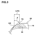
- an axially outer edge 10E of the tire of the short-fiber-mixed rubber portion 10 is located axially outer side of the tire than the grounding end Eo, and a region Y2 of a distance L between the outer edge 10E and the grounding end Eo is constituted as a sub-grounding region Y2 as shown in Fig. 3.
- the distance L is in a range of 0.05 to 0.15 times a tire width W. If the distance L is smaller than 0.05 times, the sub-grounding region Y2 becomes excessively small, and the side slip controlling effect can not be enhanced. If the distance L exceeds 0.15 times, the sub-grounding region Y2 becomes excessively large, which is not preferable from the aspect of costs.
- the values of distance L and the tire width W are of values of the above-mentioned
- an angle ⁇ of the sub-grounding region Y2 with respect to a radial direction of a tangent of the tread surface 2S is set in a range of 45 to 90°. If the angle ⁇ is less than 45°, it becomes difficult for the sub-grounding region Y2 to ground, or the grounding pressure becomes small and the side slip controlling effect can not be enhanced.
- the angle ⁇ is gradually reduced from the outer grounding end Eo toward the outer edge 10E.
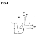
- a vertical main groove including a vertical main groove 20 extending in the circumferential direction of the tire along the outer grounding end Eo is disposed.
- a groove wall 21 on the side of the tire equator is formed as a curved surface comprising a first groove wall 21A inclining and extending from the groove bottom and a second groove wall 21B extending from a radially outer end thereof to the tread surface 2S at larger angle than the first groove wall 21A.
- An angle ⁇ 1 of the first groove wall 21A with respect to a normal of the tread surface 2S is in the conventional range of 5 to 25°.
- An angle ⁇ 2 of the second groove wall 21B is smaller than the angle ⁇ 1, and it is preferable that the ⁇ 2 is as small as possible, e.g., 0°.
- a height La of the second groove wall 21B from the tread surface 2S is preferably 0.2 to 0.5 times a groove depth H of the vertical main groove 20. Since the friction of the second groove wall 21B with respect to the road surface becomes large, the second groove wall 21B can be expected to exhibit drag with respect to the side slip, and the side slip controlling effect can further be enhanced with synergism of the above-mentioned inclination-orientation of the short fibers.
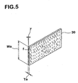
- the short-fiber-mixed rubber portion 10 is formed using a long band-like rubber strip 30 having a width Wa of 5 to 50mm and a thickness Ta of 0.5 to 3.0mm.
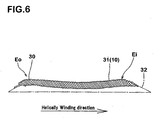
- the rubber strip 30 is wound helically on a cylindrical drum, and a strip winding body 31 having a shape close to a finished cross section shape of the short-fiber-mixed rubber portion 10 is formed.
- the strip winding body 31 is formed on a base body 32 for a base rubber layer G2 formed by extrusion using a rubber extrusion machine.
- the finished cross section shape is a cross section shape required when a raw cover of the tire is formed, and is different from a cross section shape in a finished tire after curing.
- the short fibers f of the rubber strip 30 are oriented substantially in the widthwise direction as shown in Fig. 5. That description that the short fibers f are oriented to substantially in the widthwise direction means that 65% or more, preferably 90% or more of the short fibers f are oriented to the widthwise direction at an angle of ⁇ within deviation of 0 ⁇ 15°.
- the rubber strip 30 can be obtained by helically and continuously cutting a extrusion body 33 extruded in a tube-like shape with a thickness Ta and width Wa using a rubber extrusion machine.
- This method is substantially the same as that of the conventional producing method except that the short-fiber-mixed rubber portion 10 is formed of the strip winding body 31.
- the pneumatic tire 1 is formed.
- the pneumatic tire 1 of the invention can control the side slip not only on an icy road surface but also on a wet road surface. Therefore, the invention can be employed in not only a winter tire such as studless tire or snow tire, but also in tires used for all seasons as well as a summer tire.
- the pneumatic tire of the invention can be employed in various categories such as small truck tire and heavy loading tire other than the passenger vehicle tire.
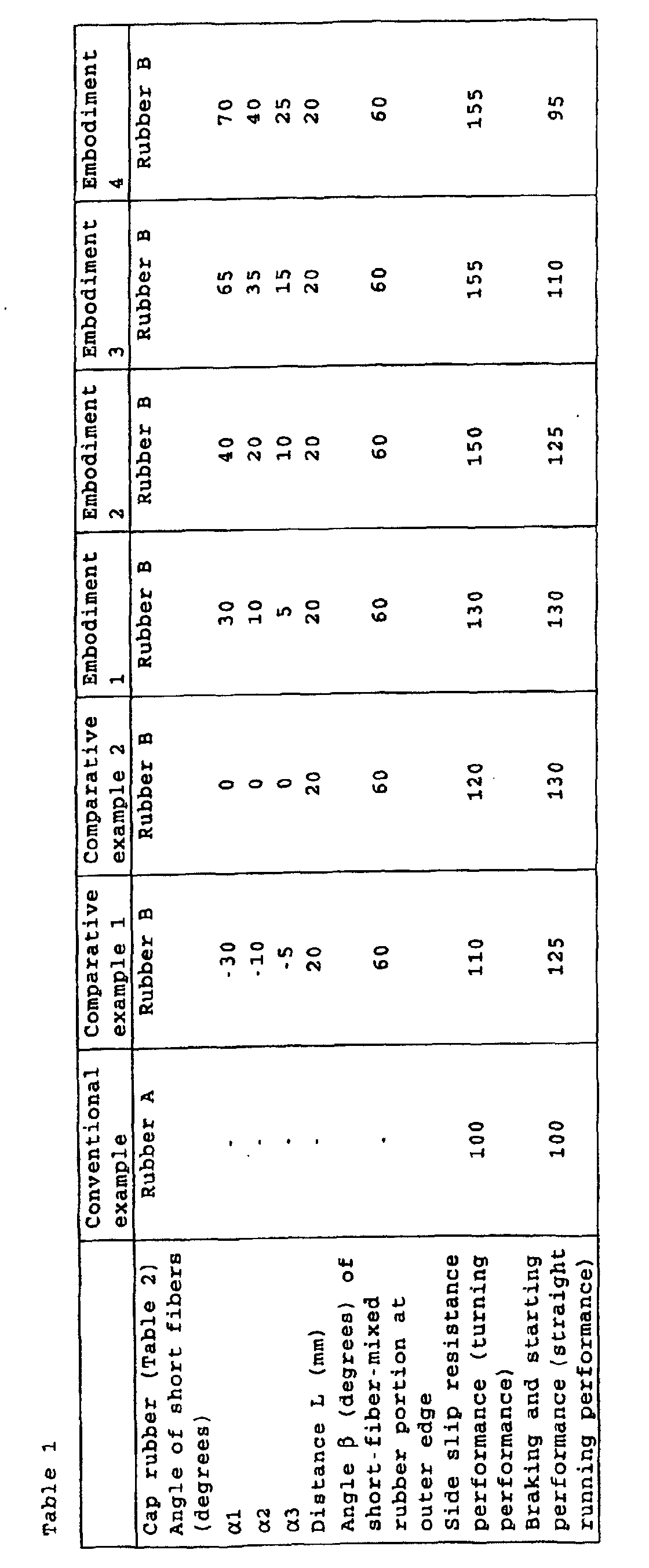
- Tires (size: 205/65R15) for a passenger vehicle having the structure shown in Fig. 1 were prototyped based on the specifications shown in Table 1, and side slip resistance performance (turning performance), and braking and starting performance (straight running performance) of each the prototyped tire was tested and compared with each other. Rubber composition of the cap rubber layer is shown in Table 2.
- the prototyped tires were mounted to four wheels of a vehicle (2,000cc/FR vehicle) under conditions of rim (6JJx15) and inner pressure (220kPa), and the vehicle turned and run on an ice surface at a temperature of 0 ⁇ 1°C (road surface temperature of -3 ⁇ 1°C) with a turning radius of 25m at 40 km/h.
- the side slip resistance performance at the time is indicated with indices by a driver's sensory evaluation while determining result of conventional examples as being 100. Higher index shows more excellent result.
- the test results confirmed that in the tires of the embodiments, the side slip resistance performance was largely enhanced and steering stability on a slippery road surface was enhanced. Especially in the embodiments 1 to 3, excellent side slip resistance performance was exhibited while highly securing the braking and starting performance.
- short fibers to be blended in a tread rubber are inclined outward of a vehicle radially outward of the tire, an inclination angle ⁇ 1 of the short fibers in the grounding end outward of the vehicle is set greater than an inclination angle ⁇ 2 of the short fibers in the tire equator. Therefore, it is possible to largely control the side slip at the time of turning of the vehicle, and to enhance the steering stability on a slippery road surface, and the pneumatic tire can suitably be used as a winter tire such as a studless tire.
Landscapes
- Engineering & Computer Science (AREA)
- Mechanical Engineering (AREA)
- Tires In General (AREA)
- Tyre Moulding (AREA)
Abstract
Description

| Rubber A | Rubber | |
| Rubber | ||
| NR | ||
| 20 | 20 | |
| SBR | 60 | 60 |
| | 20 | 20 |
| Carbon black | 40 phr | 40 |
| Silica | ||
| 6 | 6 phr | |
| Short fibers | - | Glass fiber |
| Diameter | - | 50 µm |
| Length | - | 200 µm |
| Blending amount | - | 20 phr |
| Rubber hardness (Durometer A hardness) after curing is 43°. |
Claims (6)
- A pneumatic tire wherein a tread portion comprises a short-fiber-mixed rubber portion made of short-fiber-mixed rubber produced by including short fibers in rubber, said short-fiber-mixed rubber portion forms the tread surface, in at least a region between an outer grounding end and a tire equator located outside of a vehicle when the tire is mounted to the vehicle, the short fibers are inclined and oriented at substantially an angle of α outward of the vehicle radially outward of the tire, and the angle α1 of the short fibers at the outer grounding end is greater than the angle α2 of the short fibers in the tire equator.
- A pneumatic tire according to claim 1, wherein said angle α1 is in a range of 30 to 60°, said angle α2 is in a range of 10 to 35°.
- A pneumatic tire according to claim 1 or 2, wherein an angle α3 of the side slip in the grounding end in a location inside the vehicle when the tire is mounted to the vehicle is 0 to 15° and is smaller than the angle α2 in the tire equator.
- A pneumatic tire according to any one of claims 1 to 3, wherein an outer edge of said short-fiber-mixed rubber portion on the tread surface in the axial direction of the tire is separated from the grounding end by a distance L radially outward of the tire, the distance L is 0.05 to 0.15 times of a width of the tire.
- A pneumatic tire according to any one of claims 1 to 4, wherein in a region between the grounding end and the outer edge of the short-fiber-mixed rubber portion in the axial direction of the tire, an angle b of the tread surface with respect to a radial direction of a tangent is in a range of 45 to 90°.
- A producing method of a pneumatic tire according to any one of claims 1 to 5,
said short-fiber-mixed rubber portion is formed by a strip winding body obtained by helically winding, on a cylindrical drum, a long band-like rubber strip having a width Wa of 5 to 50mm and a thickness Ta of 0.5 to 3.0mm,
short fibers of said rubber strip are oriented substantially in a widthwise direction, said rubber strip is helically wound from outside toward inside of the vehicle.
Applications Claiming Priority (3)
| Application Number | Priority Date | Filing Date | Title |
|---|---|---|---|
| JP2001297252A JP3822477B2 (en) | 2001-09-27 | 2001-09-27 | Pneumatic tire and manufacturing method thereof |
| JP2001297252 | 2001-09-27 | ||
| PCT/JP2002/009791 WO2003029030A1 (en) | 2001-09-27 | 2002-09-24 | Pneumatic tire and method of manufacturing the tire |
Publications (3)
| Publication Number | Publication Date |
|---|---|
| EP1439078A1 true EP1439078A1 (en) | 2004-07-21 |
| EP1439078A4 EP1439078A4 (en) | 2005-04-27 |
| EP1439078B1 EP1439078B1 (en) | 2006-05-10 |
Family
ID=19118363
Family Applications (1)
| Application Number | Title | Priority Date | Filing Date |
|---|---|---|---|
| EP02768031A Expired - Lifetime EP1439078B1 (en) | 2001-09-27 | 2002-09-24 | Pneumatic tire and method of manufacturing the tire |
Country Status (7)
| Country | Link |
|---|---|
| US (1) | US7131476B2 (en) |
| EP (1) | EP1439078B1 (en) |
| JP (1) | JP3822477B2 (en) |
| KR (1) | KR100762193B1 (en) |
| CN (1) | CN1251894C (en) |
| DE (1) | DE60211367T2 (en) |
| WO (1) | WO2003029030A1 (en) |
Cited By (1)
| Publication number | Priority date | Publication date | Assignee | Title |
|---|---|---|---|---|
| EP4438333A1 (en) * | 2023-03-28 | 2024-10-02 | Continental Reifen Deutschland GmbH | Tread for a vehicle tyre and method of manufacturing |
Families Citing this family (18)
| Publication number | Priority date | Publication date | Assignee | Title |
|---|---|---|---|---|
| DE10208273B4 (en) * | 2002-02-26 | 2007-04-19 | Daimlerchrysler Ag | Tires, in particular pneumatic tires, for vehicles |
| JP4653453B2 (en) * | 2004-10-20 | 2011-03-16 | 住友ゴム工業株式会社 | Method for forming raw tread rubber, and pneumatic tire using raw tread rubber formed thereby |
| EP1612034B1 (en) * | 2004-06-28 | 2008-02-20 | Sumitomo Rubber Industries, Ltd. | Method for forming a green tread rubber and a pneumatic tire formed by using the greeen tread rubber |
| JP2006051711A (en) * | 2004-08-12 | 2006-02-23 | Sumitomo Rubber Ind Ltd | Manufacturing method of rubber member for tire. |
| JP4510557B2 (en) * | 2004-09-01 | 2010-07-28 | 住友ゴム工業株式会社 | Rubber strip wound body forming device |
| JP2006219045A (en) * | 2005-02-14 | 2006-08-24 | Bridgestone Corp | Pneumatic tire, and arrangement structure and method of manufacturing for the same tire |
| WO2008027045A1 (en) * | 2006-08-31 | 2008-03-06 | Societe De Technologie Michelin | Elastomer composition having glass micro fibers |
| DE102007023726A1 (en) | 2007-05-22 | 2008-11-27 | Continental Aktiengesellschaft | Method for producing a pneumatic vehicle tire and pneumatic vehicle tires |
| KR101077590B1 (en) | 2009-02-11 | 2011-10-28 | 금호타이어 주식회사 | Tire tread rubber composition comprising silica shore fiber |
| JP2012521320A (en) * | 2009-03-20 | 2012-09-13 | イー・アイ・デュポン・ドウ・ヌムール・アンド・カンパニー | Tire tread block composition |
| FR2953456B1 (en) * | 2009-12-08 | 2011-12-09 | Michelin Soc Tech | PNEUMATIC ROLLING BELT REINFORCED BY SHORT FIBERS ORIENTED AND CROSSED BETWEEN THEM |
| US20110259492A1 (en) * | 2010-04-26 | 2011-10-27 | Richard Mbewo Samwayeba Fosam | Pneumatic tire with anisotropic tread |
| JP5478745B1 (en) * | 2013-02-20 | 2014-04-23 | 株式会社ブリヂストン | Pneumatic tire and manufacturing method thereof |
| EP3040217A1 (en) * | 2014-12-29 | 2016-07-06 | Compagnie Generale Des Etablissements Michelin | Tire having a tread with inserted fibers |
| CN104553619A (en) * | 2015-01-29 | 2015-04-29 | 双星东风轮胎有限公司 | Semi-steel radial tire blank |
| CN107791747A (en) * | 2017-10-30 | 2018-03-13 | 卢丽 | Semi-steel radial tire |
| DE102019209865A1 (en) | 2019-07-04 | 2021-01-07 | Continental Reifen Deutschland Gmbh | Method for producing a pneumatic vehicle tire, use of strip winding for winding one or more rubber components, device for carrying out the method and a pneumatic vehicle tire which can be produced or produced according to the method |
| KR20240023638A (en) | 2021-06-22 | 2024-02-22 | 화이자 인코포레이티드 | Production of Adeno-Associated Viral Vectors in Insect Cells |
Family Cites Families (24)
| Publication number | Priority date | Publication date | Assignee | Title |
|---|---|---|---|---|
| US1537456A (en) * | 1920-09-10 | 1925-05-12 | Brown John | Wear and strain resisting fabric |
| US3177918A (en) * | 1959-12-24 | 1965-04-13 | Voit Rubber Corp | Method of building a tread on pneumatic tires |
| US3308000A (en) * | 1963-08-05 | 1967-03-07 | Voit Rubber Corp | Tire tread winding machine having a punched tape control system |
| US3607497A (en) * | 1969-06-30 | 1971-09-21 | Goodyear Tire & Rubber | Tire-treading method |
| JPS5732668B2 (en) * | 1975-03-05 | 1982-07-12 | ||
| JPS5868302A (en) * | 1981-10-19 | 1983-04-23 | Sanyo Electric Co Ltd | Manufacture of microstrip line |
| JPS5868302U (en) * | 1981-10-30 | 1983-05-10 | ティーディーケイ株式会社 | tire |
| JP2733850B2 (en) * | 1989-02-13 | 1998-03-30 | 横浜ゴム株式会社 | Tread strip winding molding method |
| JPH02274602A (en) * | 1989-04-17 | 1990-11-08 | Toyo Tire & Rubber Co Ltd | Studless tire and manufacture thereof |
| US5475291A (en) * | 1992-12-10 | 1995-12-12 | Matsushita Electric Industrial Co., Ltd. | Adjustment device for adjusting control parameters of a servo motor and an adjustment method therefor |
| JPH0757539B2 (en) * | 1993-02-05 | 1995-06-21 | 住友ゴム工業株式会社 | Snow tire manufacturing method |
| DE69622601T2 (en) * | 1995-08-16 | 2003-04-24 | Helgi Geirhardsson | METHOD AND DEVICE FOR PROVIDING HARD GRANULES IN TIRE TREADS |
| US6521070B2 (en) * | 1995-08-16 | 2003-02-18 | Olafur Jonsson | Method and equipment for mixing hard granules for tire treads |
| DE69629005T2 (en) * | 1995-09-08 | 2004-06-03 | Bridgestone Corp. | RADIAL TIRE |
| JP3165645B2 (en) * | 1996-10-04 | 2001-05-14 | 住友ゴム工業株式会社 | Pneumatic radial tire |
| JP3785253B2 (en) * | 1997-08-04 | 2006-06-14 | 株式会社ブリヂストン | Manufacturing method of tread member and manufacturing method of pneumatic tire |
| JP3297643B2 (en) * | 1997-10-14 | 2002-07-02 | 東芝機械株式会社 | Servo control method and servo control device for feed drive system |
| JP4000674B2 (en) * | 1998-06-17 | 2007-10-31 | Jfeスチール株式会社 | Low carbon steel manufacturing method |
| JP4315526B2 (en) | 1998-07-08 | 2009-08-19 | 株式会社ブリヂストン | Method for laminating strip-shaped unvulcanized rubber |
| JP4308978B2 (en) * | 1999-06-17 | 2009-08-05 | 横浜ゴム株式会社 | Heavy duty pneumatic radial tire |
| CA2324807A1 (en) * | 1999-11-05 | 2001-05-05 | Sumitomo Rubber Industries, Ltd. | Studless tire with radially directed short fibers |
| JP3577248B2 (en) | 1999-11-17 | 2004-10-13 | 住友ゴム工業株式会社 | Pneumatic tire |
| US20020069948A1 (en) * | 2000-12-07 | 2002-06-13 | Sentmanat Martin Lamar | Polymeric product containing precisely located and precisely oriented ingredients |
| JP3559527B2 (en) | 2001-01-18 | 2004-09-02 | 住友ゴム工業株式会社 | Laminated rubber member forming method and apparatus used therefor |
-
2001
- 2001-09-27 JP JP2001297252A patent/JP3822477B2/en not_active Expired - Fee Related
-
2002
- 2002-09-24 WO PCT/JP2002/009791 patent/WO2003029030A1/en not_active Ceased
- 2002-09-24 EP EP02768031A patent/EP1439078B1/en not_active Expired - Lifetime
- 2002-09-24 US US10/466,874 patent/US7131476B2/en not_active Expired - Fee Related
- 2002-09-24 KR KR1020037010955A patent/KR100762193B1/en not_active Expired - Fee Related
- 2002-09-24 DE DE60211367T patent/DE60211367T2/en not_active Expired - Lifetime
- 2002-09-24 CN CNB028054741A patent/CN1251894C/en not_active Expired - Fee Related
Cited By (1)
| Publication number | Priority date | Publication date | Assignee | Title |
|---|---|---|---|---|
| EP4438333A1 (en) * | 2023-03-28 | 2024-10-02 | Continental Reifen Deutschland GmbH | Tread for a vehicle tyre and method of manufacturing |
Also Published As
| Publication number | Publication date |
|---|---|
| KR100762193B1 (en) | 2007-10-02 |
| JP3822477B2 (en) | 2006-09-20 |
| CN1492810A (en) | 2004-04-28 |
| US20040055682A1 (en) | 2004-03-25 |
| KR20040031696A (en) | 2004-04-13 |
| JP2003104013A (en) | 2003-04-09 |
| DE60211367T2 (en) | 2007-05-24 |
| EP1439078A4 (en) | 2005-04-27 |
| DE60211367D1 (en) | 2006-06-14 |
| US7131476B2 (en) | 2006-11-07 |
| CN1251894C (en) | 2006-04-19 |
| EP1439078B1 (en) | 2006-05-10 |
| WO2003029030A1 (en) | 2003-04-10 |
Similar Documents
| Publication | Publication Date | Title |
|---|---|---|
| US7131476B2 (en) | Pneumatic tire and method of manufacturing the tire | |
| JP3391692B2 (en) | Pneumatic tire | |
| JP6518660B2 (en) | Pneumatic tire | |
| JP3482033B2 (en) | Pneumatic tire | |
| CN110385944B (en) | Tyre for vehicle wheels | |
| EP3130482A1 (en) | Pneumatic radial tire for use on passenger vehicle | |
| US5117886A (en) | Pneumatic radial tire for passenger cars | |
| US20180079260A1 (en) | Pneumatic Tire | |
| EP1310385A2 (en) | Pneumatic radial tire | |
| JP2000280711A (en) | Pneumatic tire | |
| JP6605459B2 (en) | Pneumatic tire | |
| EP1097825B1 (en) | Studless tyre | |
| CN108463356A (en) | Pneumatic tire | |
| JP3203057B2 (en) | Pneumatic tire | |
| JPH05338412A (en) | Pneumatic tire for heavy load | |
| JP3763931B2 (en) | Pneumatic radial tire | |
| JP4237638B2 (en) | Pneumatic tire | |
| JPH0687303A (en) | Pneumatic tire | |
| EP0661180A1 (en) | Passenger radial tyre | |
| JP3336052B2 (en) | Pneumatic radial tire for winter | |
| JP3377262B2 (en) | Pneumatic tires for motorcycles | |
| WO2006075455A1 (en) | Pneumatic tire | |
| JPH0958212A (en) | Pneumatic tire | |
| JP2003136916A (en) | Pneumatic tire | |
| JPH09193615A (en) | Pneumatic tire |
Legal Events
| Date | Code | Title | Description |
|---|---|---|---|
| PUAI | Public reference made under article 153(3) epc to a published international application that has entered the european phase |
Free format text: ORIGINAL CODE: 0009012 |
|
| 17P | Request for examination filed |
Effective date: 20030922 |
|
| AK | Designated contracting states |
Kind code of ref document: A1 Designated state(s): AT BE BG CH CY CZ DE DK EE ES FI FR GB GR IE IT LI LU MC NL PT SE SK TR |
|
| AX | Request for extension of the european patent |
Extension state: AL LT LV MK RO SI |
|
| A4 | Supplementary search report drawn up and despatched |
Effective date: 20050315 |
|
| RIC1 | Information provided on ipc code assigned before grant |
Ipc: 7B 29D 30/66 B Ipc: 7B 60C 11/14 B Ipc: 7B 29D 30/60 B Ipc: 7B 60C 11/00 A |
|
| GRAP | Despatch of communication of intention to grant a patent |
Free format text: ORIGINAL CODE: EPIDOSNIGR1 |
|
| RBV | Designated contracting states (corrected) |
Designated state(s): DE FR GB |
|
| GRAS | Grant fee paid |
Free format text: ORIGINAL CODE: EPIDOSNIGR3 |
|
| GRAA | (expected) grant |
Free format text: ORIGINAL CODE: 0009210 |
|
| AK | Designated contracting states |
Kind code of ref document: B1 Designated state(s): DE FR GB |
|
| REG | Reference to a national code |
Ref country code: GB Ref legal event code: FG4D |
|
| REF | Corresponds to: |
Ref document number: 60211367 Country of ref document: DE Date of ref document: 20060614 Kind code of ref document: P |
|
| ET | Fr: translation filed | ||
| PLBE | No opposition filed within time limit |
Free format text: ORIGINAL CODE: 0009261 |
|
| STAA | Information on the status of an ep patent application or granted ep patent |
Free format text: STATUS: NO OPPOSITION FILED WITHIN TIME LIMIT |
|
| 26N | No opposition filed |
Effective date: 20070213 |
|
| PGFP | Annual fee paid to national office [announced via postgrant information from national office to epo] |
Ref country code: GB Payment date: 20080924 Year of fee payment: 7 |
|
| PGFP | Annual fee paid to national office [announced via postgrant information from national office to epo] |
Ref country code: DE Payment date: 20090917 Year of fee payment: 8 |
|
| PGFP | Annual fee paid to national office [announced via postgrant information from national office to epo] |
Ref country code: FR Payment date: 20091012 Year of fee payment: 8 |
|
| GBPC | Gb: european patent ceased through non-payment of renewal fee |
Effective date: 20090924 |
|
| PG25 | Lapsed in a contracting state [announced via postgrant information from national office to epo] |
Ref country code: GB Free format text: LAPSE BECAUSE OF NON-PAYMENT OF DUE FEES Effective date: 20090924 |
|
| REG | Reference to a national code |
Ref country code: FR Ref legal event code: ST Effective date: 20110531 |
|
| REG | Reference to a national code |
Ref country code: DE Ref legal event code: R119 Ref document number: 60211367 Country of ref document: DE Effective date: 20110401 |
|
| PG25 | Lapsed in a contracting state [announced via postgrant information from national office to epo] |
Ref country code: DE Free format text: LAPSE BECAUSE OF NON-PAYMENT OF DUE FEES Effective date: 20110401 Ref country code: FR Free format text: LAPSE BECAUSE OF NON-PAYMENT OF DUE FEES Effective date: 20100930 |