EP1439030A1 - Process for processing a lens - Google Patents
Process for processing a lens Download PDFInfo
- Publication number
- EP1439030A1 EP1439030A1 EP04007100A EP04007100A EP1439030A1 EP 1439030 A1 EP1439030 A1 EP 1439030A1 EP 04007100 A EP04007100 A EP 04007100A EP 04007100 A EP04007100 A EP 04007100A EP 1439030 A1 EP1439030 A1 EP 1439030A1
- Authority
- EP
- European Patent Office
- Prior art keywords
- lens
- processing
- load
- unit
- shaft
- Prior art date
- Legal status (The legal status is an assumption and is not a legal conclusion. Google has not performed a legal analysis and makes no representation as to the accuracy of the status listed.)
- Granted
Links
- 238000012545 processing Methods 0.000 title claims abstract description 173
- 238000000034 method Methods 0.000 title claims description 12
- 230000008569 process Effects 0.000 title claims description 9
- 239000000463 material Substances 0.000 claims abstract description 36
- 239000000110 cooling liquid Substances 0.000 claims abstract description 15
- 238000003825 pressing Methods 0.000 claims abstract description 8
- 230000002093 peripheral effect Effects 0.000 claims description 30
- 150000002334 glycols Chemical class 0.000 claims description 15
- 239000011347 resin Substances 0.000 claims description 12
- 229920005989 resin Polymers 0.000 claims description 12
- 229920002635 polyurethane Polymers 0.000 claims description 11
- 239000004814 polyurethane Substances 0.000 claims description 11
- 239000004721 Polyphenylene oxide Substances 0.000 claims description 6
- 239000003795 chemical substances by application Substances 0.000 claims description 6
- 239000000203 mixture Substances 0.000 claims description 6
- 229920000728 polyester Polymers 0.000 claims description 6
- 229920000570 polyether Polymers 0.000 claims description 6
- -1 aliphatic diisocyanate compound Chemical class 0.000 claims description 5
- 125000002887 hydroxy group Chemical group [H]O* 0.000 claims description 5
- 125000003118 aryl group Chemical group 0.000 claims description 4
- 150000001875 compounds Chemical class 0.000 claims description 4
- RTWNYYOXLSILQN-UHFFFAOYSA-N methanediamine Chemical compound NCN RTWNYYOXLSILQN-UHFFFAOYSA-N 0.000 claims description 4
- 238000002347 injection Methods 0.000 claims description 3
- 239000007924 injection Substances 0.000 claims description 3
- XLYOFNOQVPJJNP-UHFFFAOYSA-N water Substances O XLYOFNOQVPJJNP-UHFFFAOYSA-N 0.000 abstract description 25
- 230000003028 elevating effect Effects 0.000 description 21
- 230000001747 exhibiting effect Effects 0.000 description 15
- 238000001816 cooling Methods 0.000 description 11
- 229920003023 plastic Polymers 0.000 description 10
- 239000004033 plastic Substances 0.000 description 10
- 241001422033 Thestylus Species 0.000 description 8
- 230000003247 decreasing effect Effects 0.000 description 8
- 229910003460 diamond Inorganic materials 0.000 description 8
- 239000010432 diamond Substances 0.000 description 8
- 239000011521 glass Substances 0.000 description 8
- 238000010276 construction Methods 0.000 description 7
- 238000010586 diagram Methods 0.000 description 7
- 238000006073 displacement reaction Methods 0.000 description 7
- 230000001965 increasing effect Effects 0.000 description 6
- 230000007246 mechanism Effects 0.000 description 5
- 238000002844 melting Methods 0.000 description 5
- 230000008018 melting Effects 0.000 description 5
- 239000004417 polycarbonate Substances 0.000 description 5
- 229920000515 polycarbonate Polymers 0.000 description 5
- LYCAIKOWRPUZTN-UHFFFAOYSA-N Ethylene glycol Chemical compound OCCO LYCAIKOWRPUZTN-UHFFFAOYSA-N 0.000 description 4
- 239000000498 cooling water Substances 0.000 description 4
- 230000007423 decrease Effects 0.000 description 4
- 230000008859 change Effects 0.000 description 3
- 238000005259 measurement Methods 0.000 description 3
- 230000002411 adverse Effects 0.000 description 2
- 150000004984 aromatic diamines Chemical class 0.000 description 2
- 238000005452 bending Methods 0.000 description 2
- 238000001514 detection method Methods 0.000 description 2
- 239000000428 dust Substances 0.000 description 2
- 238000002474 experimental method Methods 0.000 description 2
- WGCNASOHLSPBMP-UHFFFAOYSA-N hydroxyacetaldehyde Natural products OCC=O WGCNASOHLSPBMP-UHFFFAOYSA-N 0.000 description 2
- 239000004925 Acrylic resin Substances 0.000 description 1
- 229920000178 Acrylic resin Polymers 0.000 description 1
- 230000015572 biosynthetic process Effects 0.000 description 1
- KORSJDCBLAPZEQ-UHFFFAOYSA-N dicyclohexylmethane-4,4'-diisocyanate Chemical compound C1CC(N=C=O)CCC1CC1CCC(N=C=O)CC1 KORSJDCBLAPZEQ-UHFFFAOYSA-N 0.000 description 1
- 239000013013 elastic material Substances 0.000 description 1
- 230000006870 function Effects 0.000 description 1
- 230000000149 penetrating effect Effects 0.000 description 1
- 239000000843 powder Substances 0.000 description 1
- 230000004044 response Effects 0.000 description 1
- 230000001360 synchronised effect Effects 0.000 description 1
- 229920001187 thermosetting polymer Polymers 0.000 description 1
- 238000009736 wetting Methods 0.000 description 1
- 238000004804 winding Methods 0.000 description 1
Images








Classifications
-
- B—PERFORMING OPERATIONS; TRANSPORTING
- B24—GRINDING; POLISHING
- B24B—MACHINES, DEVICES, OR PROCESSES FOR GRINDING OR POLISHING; DRESSING OR CONDITIONING OF ABRADING SURFACES; FEEDING OF GRINDING, POLISHING, OR LAPPING AGENTS
- B24B19/00—Single-purpose machines or devices for particular grinding operations not covered by any other main group
- B24B19/02—Single-purpose machines or devices for particular grinding operations not covered by any other main group for grinding grooves, e.g. on shafts, in casings, in tubes, homokinetic joint elements
- B24B19/03—Single-purpose machines or devices for particular grinding operations not covered by any other main group for grinding grooves, e.g. on shafts, in casings, in tubes, homokinetic joint elements for grinding grooves in glass workpieces, e.g. decorative grooves
-
- B—PERFORMING OPERATIONS; TRANSPORTING
- B24—GRINDING; POLISHING
- B24B—MACHINES, DEVICES, OR PROCESSES FOR GRINDING OR POLISHING; DRESSING OR CONDITIONING OF ABRADING SURFACES; FEEDING OF GRINDING, POLISHING, OR LAPPING AGENTS
- B24B49/00—Measuring or gauging equipment for controlling the feed movement of the grinding tool or work; Arrangements of indicating or measuring equipment, e.g. for indicating the start of the grinding operation
- B24B49/16—Measuring or gauging equipment for controlling the feed movement of the grinding tool or work; Arrangements of indicating or measuring equipment, e.g. for indicating the start of the grinding operation taking regard of the load
-
- B—PERFORMING OPERATIONS; TRANSPORTING
- B24—GRINDING; POLISHING
- B24B—MACHINES, DEVICES, OR PROCESSES FOR GRINDING OR POLISHING; DRESSING OR CONDITIONING OF ABRADING SURFACES; FEEDING OF GRINDING, POLISHING, OR LAPPING AGENTS
- B24B57/00—Devices for feeding, applying, grading or recovering grinding, polishing or lapping agents
- B24B57/02—Devices for feeding, applying, grading or recovering grinding, polishing or lapping agents for feeding of fluid, sprayed, pulverised, or liquefied grinding, polishing or lapping agents
-
- B—PERFORMING OPERATIONS; TRANSPORTING
- B24—GRINDING; POLISHING
- B24B—MACHINES, DEVICES, OR PROCESSES FOR GRINDING OR POLISHING; DRESSING OR CONDITIONING OF ABRADING SURFACES; FEEDING OF GRINDING, POLISHING, OR LAPPING AGENTS
- B24B9/00—Machines or devices designed for grinding edges or bevels on work or for removing burrs; Accessories therefor
- B24B9/02—Machines or devices designed for grinding edges or bevels on work or for removing burrs; Accessories therefor characterised by a special design with respect to properties of materials specific to articles to be ground
- B24B9/06—Machines or devices designed for grinding edges or bevels on work or for removing burrs; Accessories therefor characterised by a special design with respect to properties of materials specific to articles to be ground of non-metallic inorganic material, e.g. stone, ceramics, porcelain
- B24B9/08—Machines or devices designed for grinding edges or bevels on work or for removing burrs; Accessories therefor characterised by a special design with respect to properties of materials specific to articles to be ground of non-metallic inorganic material, e.g. stone, ceramics, porcelain of glass
- B24B9/14—Machines or devices designed for grinding edges or bevels on work or for removing burrs; Accessories therefor characterised by a special design with respect to properties of materials specific to articles to be ground of non-metallic inorganic material, e.g. stone, ceramics, porcelain of glass of optical work, e.g. lenses, prisms
Definitions
- the present invention relates to a process for processing a lens which is used for processing the peripheral portion of a lens such as a spectacle lens to provide a prescribed shape so that the lens can be fitted into a lens frame of a spectacle frame.
- the peripheral face of an uncut lens is ground by a grinder or cut by a cutter and the uncut lens is formed into a prescribed shape of the peripheral portion in accordance with data of the shape of the lens frame of the spectacle frame.
- Examples of the known processing apparatus for this purpose include, as disclosed in Laid-Open Japanese Patent Application No. 2002-18686, apparatuses in which a rotating tool (a grinder) which can be freely rotated and grinds the peripheral face of the lens is disposed around a shaft on a base and the position of grinding or cutting is set by driving a shaft supporting the lens, which can be freely swung relative to the shaft of the rotating tool, towards the shaft of the rotating tool by an arm and rotating the lens around the axis thereof.
- a rotating tool a grinder
- These apparatuses are equipped with a control portion in which selections among the types of processing such as the flat processing and the beveled processing and selection among the modes of processing such as the crude processing, the finishing, the mirror finishing, the grooving and the chamfering are made and the pressure of chucks and the tools used for the processing are set in accordance with the material of the lens (glasses, plastics, polycarbonates and acrylic resins).
- the peripheral portion of the lens is processed based on the data of the shape of the lens frame.
- the processing is conducted by setting the processing condition such as the direction of rotation of the lens axis (the up cut and the down cut) and the presence or the absence of water supply in accordance with the material of the lens.
- the condition which can be set is insufficient and the processing cannot be conducted smoothly.
- a lens exhibiting excellent impact resistance such a lens made of a polyurethane-based resin, which is formed with a polyurethane material prepared from an aliphatic diisocyanate compound, an intermediate compound having hydroxyl group selected from polyester glycols, polyether glycols and mixtures of these glycols and a curing agent of an aromatic primary diamine, has a problems in that melted dusts of grinding having shapes of ribbons and strings are occasionally attached at the peripheral portion of the processed lens in both of the wet processing using cooling water and the dry processing without using cooling water and the dust at the peripheral portion of the lens must be manually removed after the processing has been conducted. This procedure increases the time and the labor required for the processing of the lens.
- the present invention has been made to overcome the above problem and it is an object of the present invention to realize the processing operation surely based on the data of the shape of the lens frame independently of the material of the lens.
- the apparatus of the present invention for processing a lens displaces a lens supported by a holding shaft relatively to a main shaft equipped with a rotating tool and processes a peripheral portion of a spectacle lens in accordance with data of a shape of a lens frame.
- the apparatus comprises: adjusting means for adjusting a load which changes a load of pressing the lens to the rotating tool; driving means for driving a lens shaft which changes a rotation speed and a direction of rotation of the holding shaft; cooling means which injects a cooling liquid to the lens; setting means for setting processing conditions which sets controlling conditions of the adjusting means for adjusting the load, the driving means for driving a lens shaft and the cooling means, each in every step of processing the lens; and control means which controls the adjusting means for adjusting the load, the driving means for driving the lens shaft and the cooling means based on the controlling conditions set by the setting means for setting processing conditions.
- the processing can be conducted under the load, the relative directions of rotation of the lens and the rotating tool (the up cut or the down cut) and the condition of injection of cooling
- the inventive process for processing a lens comprises: displacing a lens for spectacles made of a resin and supported by a holding shaft relatively to a main shaft having a rotating tool and processing a peripheral portion of the lens in accordance with data of a shape of a lens frame.
- the lens made of a resin is formed with a polyurethane material which is prepared from an aliphatic diisocyanate compound, an intermediate compound having hydroxyl group which is selected from polyester glycols, polyether glycols and mixtures of the glycols and a curing agent of an aromatic primary diamine.
- the lens is pressed to the rotating tool under a load set at a value of 2 kgf or greater and smaller than 3 kgf, the injection of the cooling liquid is stopped, and rotation of the holding shaft and rotation of the main shaft are set at the same direction or sense.
- the load can be set as desired, not only conventional materials such as glasses, CR-39 and polycarbonates but also new materials can be processed. Since the direction of the processing (the up cut or the down cut) and the condition of water supply can be changed in every step of the processing such as the rough grinding and the finishing, materials requiring different conditions in every step can be surely processed.
- the material of the lens is a polyurethane material which is prepared from an aliphatic diisocyanate compound
- an intermediate compound having hydroxyl group which is selected from polyester glycols, polyether glycols and mixtures of the glycols and a curing agent of an aromatic primary diamine, melting (attachment) of dusts of grinding is prevented and the processing can be conducted smoothly by pressing the lens to the rotating tool under a load of 2 kgf or greater and smaller than 3 kgf and processing in the up cut condition in which the rotation of the holding shaft and the rotation of the main shaft are set in the same direction.
- Fig. 1 shows a perspective view exhibiting the appearance of an apparatus for processing a lens 10.
- Fig. 2 and 3 show perspective views exhibiting the inner construction of the apparatus.
- Fig. 4 shows a right side view exhibiting the inner construction of the apparatus.
- Fig. 1 at the right side of the front of the apparatus for processing a lens 10 contained in a case having the shape of a rectangular parallel-epiped 11, an operation portion 13 for selecting or inputting the conditions for processing the lens and a display portion 12 for displaying information on the processing such as the data of the shape of the lens frame and the data for the processing are disposed.
- the operation portion 13 is constituted with touch panels, touch switches, keys or the like.
- the display portion 12 is constituted with LCD, CRT or the like.
- a door 14 which can be opened or closed as desired and used for inserting or taking out a lens is disposed.
- a base unit 2 which can be displaced in the direction parallel with a main shaft 51 having a main rotating tool 50 (a main means for processing) (the direction of the X-axis in the Fig.) is disposed at the inside of the case 11.
- the base unit 2 supports a lens unit (a lens-holding unit) 4 which can be displaced in the vertical direction (in the direction of the Z-axis in the Figs.).
- the transverse direction of the apparatus for processing a lens 10 is assigned to the X-axis
- the vertical direction is assigned to the Z-axis
- the direction from the left to the right in Fig. 4 is assigned to the Y-axis. It is assumed that these axes orthogonally intersect each other.
- a lens-holding shaft 41 which is divided into two portions and selectively holds the center of the lens 1 between the two portions is disposed in a manner such that the lens-holding shaft can be rotated freely.
- the lens-holding shaft 41 is placed on the vertical line of the main rotating tool (a grinder or a cutter) 50 which is supported by a shaft on a base plate 15.
- the lens-holding shaft 41 and the main shaft 51 of the main rotating tool 50 are arranged parallel with each other along the X-axis.
- the lens 1 is held by the lens-holding shaft 41 in a manner such that the face of the lens 1 is placed along a plane perpendicular to the axial line of the lens holding shaft.
- a measuring unit 6 comprising styluses 60 and 61 for measuring positions on the concave face and the convex face, respectively, of the lens 1 is fixed on the vertical line of the lens-holding shaft 41.
- the styluses 60 and 61 can be displaced in the direction parallel with the lens-holding shaft 41.
- the styluses 60 and 61 are brought into contact with both faces of the lens 1 in the condition that the lens unit 4 is elevated.
- the lens unit 4 is elevated or lowered in accordance with the data of the shape of the lens frame while the lens-holding shaft is rotated and the displacements of the styluses 60 and 61 in the axial direction are detected by linear scales or the like which are not shown in the Figs.
- the lens unit 4 is lowered after the main rotating tool 50 is rotated and the peripheral portion (the outer peripheral portion) of the lens 1 is ground into the prescribed shape by elevating or lowering the lens unit 4 in accordance with the data of the shape of the lens frame while the lens-holding shaft 41 is rotated.
- the grinding to the processing depth in accordance with the rotation angle of the lens 1 is conducted continuously.
- the force of pressing the lens 1 to the main rotating tool 50 (the processing pressure) is provided by the weight of the lens unit 4 itself.
- the adjustment of the load in accordance with the material of the lens is conducted by supporting a portion of the weight of the lens unit 4 by a unit for controlling the load 8 disposed at a position above the lens unit 4.
- the position of contact between the lens 1 and the main rotating tool 50 is changed by displacing the base unit 2 in the direction of the X-axis in the Fig. and the selection between the flat grinding and the beveled grinding can be made.
- the switching between the rough grinding and the finishing grinding can also be made similarly.
- a finishing unit 7 (a means for finishing) which comprises a rotating tool for chamfering 70 and a rotating tool for grooving 71 and can be displaced in the direction of the Y-axis (in the inner direction of the apparatus) is disposed at a position above the lens unit 4.
- the rotating tool for chamfering 70 and the rotating tool for grooving 71 are placed at a position directly above the lens-holding shaft 71.
- the selection between the rotating tools 70 and 71 is made and the position of the processing is set by elevating the lens unit 4 and driving the base unit 2 in the direction of the X-axis. The finishing is conducted in this condition.
- the main shaft 51 in which the rotating tool (a grinder or a cutter having diamond or the like) 50 is disposed and a motor 55 for driving the main shaft 51 are fixed to the base plate 15 at the inside of the case 11.
- the main shaft unit is constituted with these members as the main components.
- the main shaft 51 is, as shown in Fig. 2, supported by a shaft on the base plate 15 along the X-axis in a manner such that the main shaft 51 can be rotated freely and is disposed parallel with the lens-holding shaft 41.
- a main rotating tool 50 for mechanically processing the lens 1 is attached at the end portion of the main shaft 51.
- the main rotating tool 50 is placed at the central portion in the direction of the X-axis in Fig. 2 and at the front side of the apparatus (at the lower left side in the Fig.).
- the base end portion of the main shaft (at the right side in the Fig.) is driven by a motor 55 via a belt 57 and pulleys.
- a rough grinder 50a, a finishing grinder for flat grinding 50b, a finishing grinder for beveled grinding 50c and a grinder for mirror finishing 50d are disposed successively from the side of the tip of the main shaft 51 (the left side in the Fig.).
- an electrodeposited diamond wheel or a sintered diamond wheel is used as the rough grinder 50a
- a sintered diamond wheel is used for the finishing grinder for flat grinding 50b and the finishing grinder for beveled grinding 50c
- a sintered diamond wheel is used for the grinder for mirror finishing 50d.
- the types and the positions of these grinders can be suitably exchanged with each other by detachment and attachment.
- a base unit 2 for driving the lens unit 4 in the direction of the X-axis is disposed at a position inside the main shaft 51 in Fig. 2 (in the direction of the Y-axis, at the right side in the Fig.).
- the base unit 2 is constituted with a base 20 which can be displaced in the direction of the X-axis and a servomotor 25 (hereinafter, referred to as an X-axis motor) which controls the positioning by driving the base 20 in the direction of the X-axis as the main components.
- a servomotor 25 hereinafter, referred to as an X-axis motor
- the base 20 is disposed on guide members 21 and 22 which are fixed on the base plate 15 in the direction of the X-axis in a manner such that the base 20 can be freely displaced. Therefore, the base 20 can be freely displaced in the direction of the X-axis.
- an inner screw 23 is disposed at a position below the base 20 between the guide members 21 and 22 in a manner such that the inner screw 23 can be rotated freely.
- An outer screw 24 fixed at the lower face of the base 20 is engaged with the inner screw 23 and the base 20 is driven in the direction of the X-axis by rotation of the screw 23.
- One end of the inner screw 23 and the X-axis motor 25 are connected to each other via a gear and a cogged belt 26 and the base 20 is positioned in the direction of the X-axis in accordance with the rotation angle of the X-axis motor 25.
- two poles 401 and 402 stand on the base 20, penetrate a frame 40 of the lens unit 4 and guide the lens unit 4 in the vertical direction (the direction of the Z-axis) in a manner such that the lens unit 4 can be displaced freely.
- the lens unit 4 is driven in the vertical direction and positioned in the vertical direction by the elevating and lowering unit 3 which is displaced in the direction of the Z-axis.
- the lens unit 4 is positioned in the direction of the X-axis by the base unit 2.
- the lens unit 4 supporting the lens 1 is driven in the directions of the X-axis and the Z-aXis relative to the main shaft 51.
- the elevating and lowering unit 3 is, as shown in Figs. 3, 4 and 5, constituted with a screw 31 which is supported by a shaft on the base 20 between the poles 401 and 402 and penetrates the frame 40 of the lens unit 4 in the vertical direction, a positioning member 34 which is engaged with the screw 31 at the inner peripheral portion and can support the lens unit 4 by contacting the frame 40 of the lens unit 4 at the upper end and a servomotor 33 (hereinafter, referred to as a Z-axis motor) which is connected to the lower end of the screw 31 via a cogged belt 32 and a gear, as the main components.
- the elevating and lowering unit 3 is disposed on the base 20.
- the screw 31 is rotated by driving the Z-axis motor 33 and the positioning member 34 having an outer screw 35 engaged with the screw 31 is driven in the direction of the Z-axis.
- the outer screw 35 is displaced in the direction of the Z-axis since the rotating movement in the circumferential direction is restricted by a mechanism at the lens unit 4 as shown later.
- the positioning member 34 contacts the inner periphery of a hole portion 40A formed in the frame 40 of the lens unit 4 in the vertical direction in a manner such that the positioning member 34 can slide and make a relative displacement in the vertical direction.
- a ceiling portion 400 connected to the frame 40 is disposed.
- a stopper 36 standing in the direction of the Z-axis is disposed at a position such that the stopper 36 can contact the lower face of the ceiling portion 400.
- the stopper 36 protruding from the upper portion of the positioning member 34 contacts the lower face of the ceiling portion 400 and the load of the lens unit 4 applied by the ceiling portion 400 is supported by the positioning member 34 comprising the stopper 36 and the outer screw 35.
- the outer screw 35 and the stopper 36 are connected to each other at each base portion through a base 340.
- the hole portion 40A of the frame 40 has a sectional shape such that the positioning member 34 and the stopper 36 are stopped by each other around the Z-axis (in the direction perpendicular to the plane of Fig. 6) and the idle rotation of the outer screw 35 by the rotation of the screw 31 is prevented.
- the stopper 36 fixed at the side of the outer screw 35 is arrested by the hole portion 40A and the rotation of the positioning member 34 is prevented.
- the outer screw 35 is elevated or lowered by the rotation of the screw 31 and the positioning member 34 is displaced in the direction of the Z-axis due to this movement.
- the stopper 36 does not contact the ceiling portion 400, as shown in Fig. 5, the lens 1 supported by the lens unit 4 is brought into contact with the main rotating tool 50 and the weight of the lens unit 4 itself is applied as the load.
- the upper end face 34A of the positioning member 34 and the lower face of the ceiling portion 400 do not contact each other and a prescribed gap is formed.
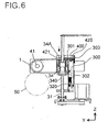
- a hole portion 421 where one end of a sensor arm 300 (a means for amplifying a relative displacement) for detecting completion of the processing of the lens unit (in the vertical direction) is inserted, is disposed along the Y-axis in the Fig. in a manner such that the hole portion 421 penetrates the frame 40 across the hole portion 40A.
- the sensor arm is, as shown in Figs. 5 and 6, an integrally formed arm having the shape of an inverse L which is composed of an arm 301 extending to the left side in the Figs. (in the direction of the Y-axis) and inserted into the hole portion 421 and an arm 302 extending in the lower direction in the Fig. (in the direction of the Z-axis, to the side of the base 20).
- the arm 301 and the arm 302 are disposed approximately perpendicularly to each other.
- the length of the arm 302 in the vertical direction is set longer than that of the arm 301 in the horizontal direction.
- a bending portion 303 at the middle of the sensor arm 300 having the shape of an inverse L is supported by a shaft 420 disposed at the ceiling portion 400 of the lens unit 4 in a manner such that the bending portion 303 can freely swing around the shaft 420 and, therefore, the sensor arm can swing around the X-axis.
- a spring 310 which pushes the arm 301 extending in the direction of the Y-axis in the lower direction in Figs. 5 and 6 (in the counter-clockwise direction in the Figs.) is disposed.
- the tip 301A of the arm 301 is brought into contact with the lower side of the hole portion 421 and stopped there in the condition that the upper end face 34A of the positioning member 34 and the arm 301 are separated from each other (in the condition that the stopper 36 is separated from the ceiling 400).
- a bracket 422 protruding along the lower portion of the sensor arm 300 (the arm 302) is disposed at the frame 40.
- a sensor for detecting completion of the processing (a means for detection) 320 which detects the free end portion of the arm 302 swinging around the X-axis is disposed.
- the free end portion means the end portion of the sensor arm 300 which is detected by the sensor for detecting completion of the processing 320 and, in the present embodiment, is the end portion of the arm 302.
- the sensor for detecting completion of the processing 320 is, for example, constituted with a photosensor such as a photointerruptor. As shown in Fig. 6, when the swinging arm 302 comes to the prescribed position (the position in the vertical direction where the lens unit 4 and the positioning member 34 are brought into contact with each other) and the light of the photointerruptor of the sensor for detecting completion of the processing is interrupted, the sensor is switched at ON and it is detected that the processing has been completed.
- the elevating and lowering unit 3 supports the lens unit 4 in the elevating direction.
- the processing depth (the processing amount) is decided in accordance with the position of the elevating and lowering unit 3 in the direction of the Z-axis.
- the sensor for detecting completion of the processing 320 is switched at ON. The proceeding of the processing can be detected at every rotation angle of the lens 1 in this manner and, when the output of the sensor for detecting completion of the processing at the entire peripheral portion of the lens 1 shows ON, it is decided that the processing has been completed on the entire peripheral portion of the lens 1.
- the elevating and lowering unit 3 supports the lens unit 4 in the direction of elevation and, after the processing of the lens 1 has been started by the lens unit 4, the processing depth (the processing amount) is decided in accordance with the position of the elevating and lowering unit 3 in the direction of the Z-axis.
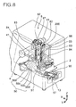
- the lens unit 4 which is displaced by the elevating and lowering unit 3 in the direction of the Z-axis is, as shown in Figs. 2 and 7, guided by the two poles 401 and 402 standing on the base 20 in the vertical direction (in the direction of the Z-axis) in a manner such that the lens unit can be freely displaced and is constituted with the lens-holding shaft 41 which is divided into two portions, a motor for driving the lens 45 which rotates the lens-holding shaft 41 and a motor for the lens chuck 46 which changes the pressure of the lens-holding shaft 41 to hold the lens 1, as the main components.
- the lens-holding shaft 41 which holds and rotates the lens 1 is placed at a position directly above the main rotating tool 50.
- the direction connecting the axial line of the lens-holding shaft 41 and the axial line of the main shaft 51 is in the vertical direction.
- arms 410 and 411 protruding in the direction of the front of the apparatus are disposed and the frame 40 and the arms 410 and 411 form a rectangle having three sides and open to one side.
- the arms 410 and 411 support the lens-holding shaft 41.
- the lens-holding shaft 41 is divided into two portions at the center, i.e., a shaft 41R supported by the arm 410 and a shaft 41L supported by the arm 411.
- the arm 41L is supported by the arm 411 at the left side in Fig. 8 in a manner such that the arm 41L is freely rotated.
- the arm 41R is supported by the arm 410 at the right side in Fig. 8 in a manner such that the arm 41L is freely rotated and can be displaced in the axial direction (in the direction of the X-axis).
- the shafts 41L and 41R are rotated by the motor 45 for driving the lens via cogged belts 47, 48 and 49.
- the cogged belts 47 and 48 are connected to each other through a shaft 43 0 and the rotation angles of the shafts 41L and 41R are synchronized.
- a gear 432 engaged with the cogged belt 47 is fixed to the shaft 41L and a gear 431 engaged with the cogged belt 48 is fixed to the shaft 41R. So that the shaft 41R can be displaced relative to the arm 410 in the direction of the X-axis, the shaft 41R is arrested in the direction of rotation by the key 433 disposed between the shaft 41R and the inner periphery of the gear 431 and, on the other hand, can be relatively displaced in the direction of the X-axis.
- a chuck mechanism driven by a motor for the lens chuck 46 is disposed at the end portion (at the right side in the Fig.) of the shaft 41R.
- the shaft 41L penetrates the arm 411 and a slit plate 143 is fixed at the end portion protruding from the arm 411.
- a photosensor 145 a lens position sensor, a means for detecting the angle
- the lens unit 4 having the construction described above, when the lens 1 is fixed at the receiver of the lens holder 141, the motor for the lens chuck 46 is driven and the lens-holding shaft 41R is moved to the left side of Fig. 9.
- the lens 1 is fixed by pressing the lens 1 by the lens presser 142 under the pressure.
- the lens-holding shaft 41L and 41R are rotated by driving the motor for driving the lens 45 and the lens 1 is rotated.
- the main rotating tool 50 is fixed to the base plate 15 and is not displaced.
- the lens 1 supported by the lens unit 4 is displaced in the vertical direction relative to the main rotating tool 50 by the displacement of the elevating and lowering unit 3 in the direction of the Z-axis and the processing can be conducted to the desired depth.
- the position of the lens 1 for the processing can be changed by changing the rotation angle of the motor for driving the lens 46 and the peripheral portion of the lens 1 can be processed to the desired processing depth.
- the tool used for the processing can be changed by changing the position of contact between the lens 1 and the main rotating tool 50 by the displacement of the base 20 in the direction of the X-axis.
- the unit for controlling the load (for adjusting the load) 8 for controlling the pressure of pressing the lens 1 supported by the lens unit 4 to the main rotating tool 50 will be described.
- the unit for controlling the processing pressure 8 is, as shown in Figs. 4 and 8, fixed on an upper base 200 which is disposed at upper ends of poles 401 to 404 standing on the base plate 2 and is displaced in the direction of the X-axis in combination with the lens unit 4.
- the unit for controlling the load 8 is constituted with pulleys 82 and 82 driven by a motor for controlling the load 81 (an actuator), wires 83 wound around the pulleys 82 and springs (an elastic member) 84 connecting the wires 83 to the frame 40 of the lens unit 4, as the main components.
- the motor for controlling the load 81 and the pulleys 82 and 82 are connected to each other via a worm gear 87.
- the lens unit 4 is suspended with pairs of pulleys 82 (winding members), the wires 83 (suspending members) and the springs 84.
- the numbers of the wire 83 and the spring 84 can be selected as desired.
- the force of pressing the lens 1 to the main rotating tool is the weight of the lens unit 4 itself.
- the load the surface pressure
- the load the surface pressure
- the amount of unwinding the wires 83 is adjusted by the motor for controlling the load 81 in accordance with the displacement of the lens unit in the direction of the Z-axis so that the tension of the springs 84 is held approximately constant.
- the amount of unwinding the wires 83 is controlled in accordance with the rotation angle and the number of rotation of the pulleys 82 which are detected by the slit plate 85 disposed coaxially with the pulleys 82 and a photosensor 86 detecting the passage of the slit.
- the amount of driving the Z-axis motor 42 for example, the output of the encoder in the case of a servomotor and the number of steps in the case of a step motor
- a value obtained by directly measuring the position of the lens unit 4 or the lens-holding shaft 41 along the Z-axis can be used.
- the tension of the springs 84 decrease and the load increases as the amount of unwinding the wires 83 increases, and the tension of the springs 84 increases and the load decreases as the amount of unwinding the wires 83 decreases.
- the amount of unwinding can be decreased as the lens unit is elevated at a higher position and the amount of unwinding the wires 83 can be increased as the processing by the lens unit 4 proceeds using a linear table or the map shown in Fig. 9.
- the load can be selected based on a plurality of properties shown in Fig. 9 based on the material input as the information and the thickness of the peripheral portion or the relation between the amount of unwinding and the position of the lens unit 4 (a proportional relation) is obtained by calculation.
- the thickness of the peripheral portion varies depending on the position of processing, different properties may be selected in accordance with the rotation angle of the lens-holding shaft 41 (the position of processing the lens).
- the position of the lens unit in the direction of the Z-axis is decided by the elevating and lowering unit 3 described above. As shown in Fig. 13, since the processing is conducted while the lens 1 supported by the lens-holding shaft 41 is rotated, the position in the direction of the Z-axis always changes. As shown in Figs. 5 and 6, the position of the lens unit 4 at the start of the processing is different from that at the end by the processing depth.
- the load close to the set value can be maintained by the change in the length of the springs 84 even when the amount of unwinding the wires 83 cannot follow the change in the position of the lens unit 4. Therefore, the load of calculation required for the control can be decreased remarkably.
- the cooling unit for supplying a cooling liquid during the processing of the lens will be described in the following.
- the cooling unit is used for cooling the uncut lens 1 and the tools and removes dusts of grinding.
- a cooling liquid comprising water as the main component is used.
- the cooling unit is, as shown in Figs. 10 and 2, constituted with a waterproof case 101 which has the shape of a box and surrounds the main rotating tool 50, the lens 1 supported by the lens-holding shaft 41, the styluses 60 and 61 and the rotating tools 70 and 71 of the finishing unit 7, a nozzle 102 injecting the cooling liquid to the vicinity of the lens 1 held by the lens-holding shaft 41, a tank 103 disposed at a position below the waterproof case 101 and a pump 104 sending the cooling liquid in the tank 103 to the nozzle 102 under a pressure.
- a waterproof case 101 which has the shape of a box and surrounds the main rotating tool 50, the lens 1 supported by the lens-holding shaft 41, the styluses 60 and 61 and the rotating tools 70 and 71 of the finishing unit 7, a nozzle 102 injecting the cooling liquid to the vicinity of the lens 1 held by the lens-holding shaft 41, a tank 103 disposed at a position below the waterproof case 101 and a pump 104 sending the cooling liquid in the
- a door 14 which can be opened and closed is disposed (refer to Fig. 1).
- the lens is attached or detached.
- the door is closed, the inside of the waterproof case 101 is tightly closed and wetting of the bearing of the main shaft 51, the motors, the power source and the electric circuits with the scattered cooling liquid injected in the waterproof case 101 is prevented.
- the cooling liquid used for cooling the lens 1 and the rotating tools during the processing returns to the tank 103, sucked into the pump 104 and circulated. Since the cooling liquid used for cooling the lens 1 contains dusts formed by processing the lens 1, a drain which can be opened and closed is attached to the tank 103 so that the dusts formed by the cutting can be removed and the cooling liquid can be exchanged with the fresh cooling liquid.
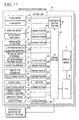
- the apparatus for processing a lens 10 is constituted with the various mechanisms (units) described above and further has a control portion 9 for controlling the mechanisms as shown in Fig. 11.
- the control portion 9 is constituted with a microprocessor (CPU) 90, a means for memory (a memory, a hard disk and the like) 91 and an I/O control portion (an interface) 92 connected to the motors and the sensors as the main components.
- the control portion 9 reads the data of the shape of the lens frame sent from the apparatus for measuring the shape of the frame 900 placed at the outside.
- the control portion 9 also reads the data from various sensors and drives the various motors so that the prescribed processing is conducted based on the properties (the material, the hardness and the like) of the lens 1 set by the operation portion 13.
- an apparatus for measuring the shape of the frame an apparatus such as the apparatus disclosed in Laid-Open Japanese Patent Application No. Heisei 6(1994)-47656 can be used.
- the control portion 9 comprises a servomotor control portion 93 which positions the lens unit 4 in the directions of the X-axis and the Z-axis by driving the X-axis motor 25 of the base unit 2 and the Z-axis motor 42 of the elevating and lowering unit 3.
- the motor 55 for driving the main rotating unit 50, the motor for finishing 72 which drives the rotating tools 70 and 71 and the pump 104 of the cooling unit are each connected to the I/O control portion 92 via driving portions 901, 902 and 903, respectively, and the condition of rotation or the speed of rotation is controlled in accordance with the direction from the microprocessor 90.
- the driving portion 901 of the motor 55 of the main shaft is constituted, for example, with an inverter and the main rotating tool 50 is driven at the desired speed of rotation.
- the motor for the lens chuck 46 which controls the holding pressure applied to the lens 1 by changing the length of the shaft 41R of the lens-holding shaft 41 is connected to the I/O control portion 92 via a driving portion 911 which controls the holding pressure in accordance with the electric current of driving.
- the motor 45 for driving the lens is connected to the I/O control portion 92 via a driving portion 912 which controls the rotation angle of the lens-holding shaft 41 (the lens 1).
- the microprocessor 90 directs the position of processing the lens 1 based on the data of the shape of the lens frame obtained from the apparatus for measuring the shape of the frame 900, detects the rotation angle of the lens 1 by the sensor for detecting the position of the lens 145 and drives the Z-axis motor 42 so that the processing depth in accordance with the rotation angle based on the data of the shape of the lens frame is achieved.
- a sensor for detecting completion of processing 320 which will be described later is switch at ON and the actual position of processing is fed back to the microprocessor 90.
- the motor for driving the finishing unit 73 which drives the finishing unit 7 in the direction of the Y-axis, the motor for driving styluses 62 which drives the styluses 60 and 61 of the measuring unit 6 and the motor for controlling the processing pressure 81 of the unit for controlling the load 9 are each connected to the I/O control portion 92 via driving portions 913, 914 and 915, respectively, which control the positioning.
- the outputs of linear scales 600 and 601 connected to the styluses 60 and 61, respectively, of the measuring unit 6 are input into a counter 920.
- the microprocessor 90 reads the values in the counter 920 and measures the position of the peripheral portion (the position of the finished portion) of the lens 1.
- a photosensor 86 (a sensor for the position of the wire) of the unit for controlling the load 8 detects the rotation angle of the pulley 82.
- the microprocessor 90 drives the motor for controlling the load 81 in a manner such that the load set in accordance with the position of the lens unit 4 in the direction of the Z-axis is maintained.
- the operation portion 13 disposed at the front of the cover of the apparatus for processing a lens 10 is connected to the I/O control portion 92 and transfers the directions from the operator (the material of the lens 1 and the processing with or without the beveled processing or the grooving) to the microprocessor 90.
- the microprocessor 90 outputs the response to the directions and the information of the content of the processing to the display portion 12 via the driving portion 921.
- Fig. 12 shows a block diagram exhibiting the function of the operation portion 13 and the control portion 9.
- the operation portion 13 comprises a means for manual setting 13A for manually setting the conditions of the processing and a means for presetting 13B in which the conditions of the processing set in advance are classified with respect to the material.
- the means for manual setting 13A is constituted with a portion for setting the processing mode 130 which selects the step of the processing from steps such as the rough processing, the finishing (the flat finishing or the beveled finishing) and the mirror finishing (the flat mirror finishing or the beveled mirror finishing), a portion for setting the rotation speed of the mains shaft 131 which sets or selects the rotation speed of the main shaft 51, a portion for setting the rotation speed of the lens 132 which sets or selects the rotation speed of the lens-holding shaft 41, a portion for setting a load 133 which sets or selects the load (kgf) applied to the lens 1 by the lens unit 4 and a portion for setting the condition of water supply 134 which sets or selects the condition of the use of the cooling water.
- the portion for setting the processing mode 130 for example, one of the rough processing, the finishing (the flat finishing and the beveled finishing), the mirror finishing (the flat mirror finishing and the beveled mirror finishing), the chamfering and the grooving is selected using ten keys or touch switches.
- the value set at the portion for setting the processing mode 130 is input into a portion for selecting the tool in the control portion 9 and the position of the lens unit 4 in the direction of the X-axis is set so that the lens 1 is placed at the position corresponding to the tool for the selected processing mode.
- a desired rotation speed (rpm) is input using ten keys, or a desired rotation speed is selected from a plurality of speeds (such as high, medium and low) set in advance using touch switches.
- the value set at the portion for setting the rotation speed of the main shaft 131 is input into a portion for setting the rotation speed of the mains shaft 941 of the control portion 9 and the control parameter is set so that the motor is controlled at the set value.
- a desired rotation speed (rpm) is input using ten keys, or a desired rotation speed is selected from a plurality of speeds set in advance using touch switches.
- the value set at the portion for setting the rotation speed of the lens shaft 132 is input into a portion for setting the rotation speed of the lens 942 in the control portion 9 and the control parameter is set so that the motor for driving the lens 45 is controlled at the set value.
- the direction (positive or negative) of rotation of the lens-holding shaft 41 can also be set.
- the lens-holding shaft 41 and the main shaft 51 are rotated in the same direction and the grinding is conducted as the up cut and, when the direction of the rotation is negative, the lens-holding shaft 41 and the main shaft 51 are rotated in different directions and the grinding is conducted as the down cut.
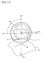
- the up cut for example, as shown in Fig. 13, the lens-holding shaft 41 and the main shaft 51 are both rotated in the clockwise direction and the lens 1 and the rotating tool 50 at the main shaft 51 are displaced in different directions at the position of the grinding.
- the movements are reversed and the lens 1 and the rotating tool 50 at the main shaft 51 are displaced in the same direction at the position of the grinding.
- a desired load (kgf) is input using ten keys, or a desired load is selected from a plurality of loads (such as high, medium and low) set in advance using touch switches.
- the value set at the portion for setting a load 133 is input into a portion for deciding the properties 943 in the control portion 9 and the driving pattern of the motor for controlling the load 81 is set so that load is controlled at the set value as shown in Fig. 9.
- a pattern of water supply is selected from a plurality of patterns of water supply set in advance using touch switches. For example, a pattern of water supply is selected from no water supply at all (the dry processing), continuous water supply (the wet processing) and water supply started during the processing.
- the value set at the portion for setting the condition of water supply 134 is input into a portion for deciding the pattern 944 of the control portion 9 and the pattern of driving the pump 104 is set so that the water supply is controlled in accordance with the set pattern of water supply.
- the pattern of the processing is set in advance in accordance with the material of the lens 1.
- the rotation speed of the main shaft, the rotation speed of the lens shaft, the load and the pattern of water supply are set into a table 945 in the control portion 9 for every processing mode.
- Fine adjustment can be made for each processing mode by selection using the means for manual setting 13A after one of the selection switches 135 to 138 in the means for presetting 13B has been pushed in accordance with the material of the lens.
- the processing decided by the means for manual setting 13A or the means for presetting 13B can be started by pushing a starting button not shown in the Fig.
- the operation portion 13 may further comprise a portion for setting the chuck pressure for setting the driving power of the motor for the lens chuck 46 and a portion for controlling the chuck pressure for setting the control parameters in accordance with the set value so that the pressure of holding the lens 1 can be changed as desired.
- Fig. 14 the procedures conducted by the control portion 9 after the lens 1 is set into the lens-holding shaft 41 are shown.
- the data of the shape of the lens frame are read at the apparatus for measuring the shape of the frame 900 and the position for the grinding is calculated.
- step S1 the shaft 41R of the lens-holding shaft 41 is displaced to the position for holding the lens 1 by driving the motor for the lens chuck 46 and the lens 1 is held under a pressure in accordance with the material of the lens 1.
- the lens unit 4 is elevated or lowered in accordance with the data of the shape of the lens frame and is positioned at the prescribed position for the measurement.
- step S2 the styluses 60 and 61 are brought into contact with the convex face 1a and the concave face 1b, respectively, of the lens 1 by driving the motor 62 for driving the styluses.
- the lens 1 is rotated by driving the motor for driving the lens 45.
- the lens unit 4 is elevated or lowered to the position in accordance with the rotation angle of the lens 1 (the position of the complete processing on the peripheral portion of the lens) based on the data of the shape of the lens frame (the data of the peripheral portion of the lens 1) and the position of the complete processing on the lens 1 is measured and stored into the means of memory 91.
- step S3 the rough grinding is conducted in step S3.
- the lens unit 1 is moved to the prescribed position relative to the main rotating tool 50 (for example, the position directly above the rough grinder 50a in Fig. 2) by driving the base unit 2 and the elevating and lowering unit 3.
- the rough grinding is conducted by driving the motor 55 at the prescribed rotation speed and the lens 1 is formed into an approximately the same shape as that of the lens frame.
- the load, the rotation speed of the lens shaft and the pattern of water supply are controlled based on the set values.
- the flat finishing or the beveled finishing is conducted in accordance with the presence or the absence of the bevel using the main rotating tool 50 based on the set values (steps S4 and S8).
- the mirror finishing is conducted using the main rotating tool 50 based on the set values (steps S5 and S9).
- step S6 When the above grinding is the flat grinding, the grooving of the peripheral face of the lens is conducted using the rotating tool 71 (step S6). In the final step, the chamfering of the peripheral portion of the lens is conducted using the rotating tool 70 (step S7). A series of processing steps are completed as described above.
- Fig. 15 shows an example of the setting of the table 945 shown in Fig. 12.
- Fig. 15 (A) shows a table for the rough grinding and
- Fig. 15 (B) shows a table for the finishing.
- the conditions of the processing are set in advance as follows: the grinding speed: 1,000 m/min; the rotation speed of the lens shaft: 5 to 6 rpm; the direction of the grinding: down cut; the load: 3.5 to 4 kgf; the dry processing without water supply in the rough grinding; and the wet processing with continuous water supply in the finishing. (When the value is shown by a range, the central value is used for the setting.)
- the lens has a problem in that melted dusts of grinding having shapes of ribbons and strings are occasionally attached to the peripheral portion of the processed lens when the processing is conducted using a conventional apparatus and the processing conducted after the above step such as the finishing, the chamfering and the grooving is occasionally adversely affected.
- the dusts of grinding removed from the peripheral portion of the lens are occasionally attached to and accumulated at the inner periphery of the apparatus and adversely affect the movement of the tools and the lens.
- An example of the lens described above is formed with a polyurethane which is obtained by reacting a polyester glycol or a polyether glycol having a weight-average molecular weight of about 600 to about 1,200 with 4,4'-methylenebis(cyclohexyl isocyanate) in relative amounts by equivalent of 2.5 to 4.5 NCO per OH and preferably 3 to 3.5 NCO per OH to form a prepolymer, followed by reacting the formed prepolymer with a curing agent of an aromatic diamine in relative amounts by equivalent of 0.95 to 1.02 NH 2 /1.0 NCO and preferably 0.96 to 1.0 NH 2 /1.0 NCO.
- the lens made of the resin having the above composition will be referred to as the polyurethane lens having difficulty in grinding.
- the load cannot be set as desired. Even when the load can be changed, the load can be changed in the direction of increasing the load from the ordinary value (about 3.5 to 4.0 kgf), i.e., in the direction of decreasing the time of processing, such as a load of 4.0 kgf or greater, but cannot be changed to a value smaller than the ordinary value (3.5 kgf). Therefore, the condition for preventing the formation of the dust of grinding having shapes of ribbons and strings cannot be found in the processing of the polyurethane lens having difficulty in grinding.
- the polyurethane lens having difficulty in grinding can be surely processed by setting the rotation speed of the main shaft, the rotation speed of the lens shaft, the direction of grinding (the direction of rotation of the lens shaft), the load and the pattern of water supply as desired.
- the characteristic line L1 corresponds to a load of 4 kgf
- the characteristic line L2 corresponds to a load of 3.5 kgf
- the characteristic line L3 corresponds to a load of 2 kgf.
- the melting of the dusts of grinding can be surely prevented when the load is set at a value smaller than 3 kgf, the dry processing is conducted in the up cut condition, the speed of grinding is increased to a value greater than the ordinary value of 1,000 m/min by 10% or greater, and the rotation speed of the lens shaft is increased to a value about twice as fast as the ordinary value.
- the speed of grinding changes depending on the relative rotating speeds of the main shaft and the lens shaft. In the above, the rotation speed of the lens shaft is neglected since the rotation speed of the lens shaft is much smaller than the rotation speed of the main shaft.
- the rotation speed of the lens shaft and the direction of the rotation are taken into consideration.
- the rotating speed of the main shaft may be listed in the table in place of the speed of grinding.
- the time when the dry processing is changed to the wet processing during the processing is in the final step or in the later steps of the processing.
- the dry processing can be changed to the wet processing when the margin for the grinding reaches 0.1 to 0.2 mm in the radial direction.
- a conventionally used sintered diamond grinder for finishing can be used as the rotating tool 50. It is preferable that the speed of grinding and the rotation speed of the lens shaft are changed when the rotating tool 50 is changed.
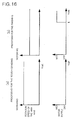
- the dry processing is conducted at a great speed of grinding (for example, 1,256 m/min) as shown in Fig. 16(A).
- a great speed of grinding for example, 1,256 m/min
- the speed of grinding is decreased and the finishing is started in accordance with the dry processing.
- the supply of water is started and the cooling liquid is injected to the lens 1.
- the processing is converted into the wet processing in the later stage of the finishing.
- the processing can be conducted not only for conventional materials such as glasses, CR-39 and polycarbonates but also for new materials. Since the direction of processing (the up cut or the down cut), the speed of grinding and the condition of water supply can be changed at every step such as the rough grinding and the finishing, the processing can be conducted surely even when the conditions of the processing are different among the steps as shown for the lens having difficulty in grinding.
- the weight of the lens unit 4 is adjusted in accordance with the tension of the spring 84 in the unit for controlling the load 8.
- an elastic material may be used as the wire 83 in place of the spring 84.
- the unit for controlling the processing pressure 8 has the construction such that the lens unit 4 is suspended from an upper position. Alternatively, the lens unit 4 may be pushed from a lower position to the upward direction.
- the unit for controlling the load 8 supports a portion of the weight of the lens unit 4 via the spring 84.
- the lens unit 4 may be directly suspended by the wire 83 and the load applied to the lens 1 may be adjusted in accordance with the force of driving or the amount of driving of the motor 81.
- the apparatus for processing a lens is the so-called apparatus of the vertical movement which conducts the processing with the displacement of the lens 1 in the vertical direction.
- the present invention can also be applied to an apparatus which conducts the processing by supporting the lens by an arm swinging relative to the main shaft in the conventional manner.
Landscapes
- Engineering & Computer Science (AREA)
- Mechanical Engineering (AREA)
- Chemical & Material Sciences (AREA)
- Ceramic Engineering (AREA)
- Inorganic Chemistry (AREA)
- Grinding And Polishing Of Tertiary Curved Surfaces And Surfaces With Complex Shapes (AREA)
- Eyeglasses (AREA)
- Constituent Portions Of Griding Lathes, Driving, Sensing And Control (AREA)
- Grinding-Machine Dressing And Accessory Apparatuses (AREA)
Abstract
Description
- The present invention relates to a process for processing a lens which is used for processing the peripheral portion of a lens such as a spectacle lens to provide a prescribed shape so that the lens can be fitted into a lens frame of a spectacle frame.
- Heretofore, when a lens such as a spectacle lens is processed so that the lens is fitted into a lens frame of a spectacle frame, the peripheral face of an uncut lens is ground by a grinder or cut by a cutter and the uncut lens is formed into a prescribed shape of the peripheral portion in accordance with data of the shape of the lens frame of the spectacle frame.
- Examples of the known processing apparatus for this purpose include, as disclosed in Laid-Open Japanese Patent Application No. 2002-18686, apparatuses in which a rotating tool (a grinder) which can be freely rotated and grinds the peripheral face of the lens is disposed around a shaft on a base and the position of grinding or cutting is set by driving a shaft supporting the lens, which can be freely swung relative to the shaft of the rotating tool, towards the shaft of the rotating tool by an arm and rotating the lens around the axis thereof.
- These apparatuses are equipped with a control portion in which selections among the types of processing such as the flat processing and the beveled processing and selection among the modes of processing such as the crude processing, the finishing, the mirror finishing, the grooving and the chamfering are made and the pressure of chucks and the tools used for the processing are set in accordance with the material of the lens (glasses, plastics, polycarbonates and acrylic resins). The peripheral portion of the lens is processed based on the data of the shape of the lens frame.
- In recent years, various types of resins are used for the lens so that the refractive index is increased and the impact resistance is improved. Processability is different depending on the material.
- In the conventional apparatuses described above, the processing is conducted by setting the processing condition such as the direction of rotation of the lens axis (the up cut and the down cut) and the presence or the absence of water supply in accordance with the material of the lens. When a lens made of a new material is processed, occasionally, the condition which can be set is insufficient and the processing cannot be conducted smoothly.
- For example, as disclosed in Laid-Open Japanese Patent Application (as a national phase under PCT) Nos. 2000-511231 and 2002-504935, the processing of a lens exhibiting excellent impact resistance such a lens made of a polyurethane-based resin, which is formed with a polyurethane material prepared from an aliphatic diisocyanate compound, an intermediate compound having hydroxyl group selected from polyester glycols, polyether glycols and mixtures of these glycols and a curing agent of an aromatic primary diamine, has a problems in that melted dusts of grinding having shapes of ribbons and strings are occasionally attached at the peripheral portion of the processed lens in both of the wet processing using cooling water and the dry processing without using cooling water and the dust at the peripheral portion of the lens must be manually removed after the processing has been conducted. This procedure increases the time and the labor required for the processing of the lens.
- The present invention has been made to overcome the above problem and it is an object of the present invention to realize the processing operation surely based on the data of the shape of the lens frame independently of the material of the lens.
- This object is solved by the process as defined in
claim 1. An advantageous further devolopement of the invention is provided in the subclaim. - The apparatus of the present invention for processing a lens displaces a lens supported by a holding shaft relatively to a main shaft equipped with a rotating tool and processes a peripheral portion of a spectacle lens in accordance with data of a shape of a lens frame. The apparatus comprises: adjusting means for adjusting a load which changes a load of pressing the lens to the rotating tool; driving means for driving a lens shaft which changes a rotation speed and a direction of rotation of the holding shaft; cooling means which injects a cooling liquid to the lens; setting means for setting processing conditions which sets controlling conditions of the adjusting means for adjusting the load, the driving means for driving a lens shaft and the cooling means, each in every step of processing the lens; and control means which controls the adjusting means for adjusting the load, the driving means for driving the lens shaft and the cooling means based on the controlling conditions set by the setting means for setting processing conditions. The processing can be conducted under the load, the relative directions of rotation of the lens and the rotating tool (the up cut or the down cut) and the condition of injection of cooling water in accordance with the material of the lens which may be different in each case.
- The inventive process for processing a lens comprises: displacing a lens for spectacles made of a resin and supported by a holding shaft relatively to a main shaft having a rotating tool and processing a peripheral portion of the lens in accordance with data of a shape of a lens frame. The lens made of a resin is formed with a polyurethane material which is prepared from an aliphatic diisocyanate compound, an intermediate compound having hydroxyl group which is selected from polyester glycols, polyether glycols and mixtures of the glycols and a curing agent of an aromatic primary diamine. In the processing, the lens is pressed to the rotating tool under a load set at a value of 2 kgf or greater and smaller than 3 kgf, the injection of the cooling liquid is stopped, and rotation of the holding shaft and rotation of the main shaft are set at the same direction or sense.
- In accordance with the present invention, since the load can be set as desired, not only conventional materials such as glasses, CR-39 and polycarbonates but also new materials can be processed. Since the direction of the processing (the up cut or the down cut) and the condition of water supply can be changed in every step of the processing such as the rough grinding and the finishing, materials requiring different conditions in every step can be surely processed.
- When the material of the lens is a polyurethane material which is prepared from an aliphatic diisocyanate compound, an intermediate compound having hydroxyl group which is selected from polyester glycols, polyether glycols and mixtures of the glycols and a curing agent of an aromatic primary diamine, melting (attachment) of dusts of grinding is prevented and the processing can be conducted smoothly by pressing the lens to the rotating tool under a load of 2 kgf or greater and smaller than 3 kgf and processing in the up cut condition in which the rotation of the holding shaft and the rotation of the main shaft are set in the same direction.
-
- Fig. 1
- shows a perspective view of the appearance of the apparatus for processing a lens as an embodiment of the present invention;
- Fig. 2
- shows a perspective view exhibiting the main portions of the inner construction;
- Fig. 3
- shows a perspective view exhibiting the inner construction in the condition that the measuring unit and the finishing unit are removed;
- Fig. 4
- shows a right side view exhibiting the inner construction;
- Fig. 5
- shows a sectional view of the elevating and lowering unit and the lens unit in the vertical direction when the processing is started;
- Fig. 6
- shows a sectional view of the elevating and lowering unit and the lens unit in the vertical direction when the processing is completed;
- Fig. 7
- shows a sectional view of the elevating and lowering unit and the lens unit in the horizontal direction in the condition that the lens is held by the lens-holding shafts;
- Fig. 8
- shows a perspective view exhibiting the relation between the unit for controlling the load and the lens unit;
- Fig. 9
- shows a table describing the relation between the amount of unwinding the wire and the position of the lens unit using the load as the parameter;
- Fig. 10
- shows a schematic front view of the cooling unit;
- Fig. 11
- shows a schematic diagram exhibiting the control portion;
- Fig. 12
- shows a block diagram exhibiting the operation portion and the control portion;
- Fig. 13
- shows an expanded view of the lens and the main rotating tool during the processing;
- Fig. 14
- shows a diagram exhibiting the steps of processing the lens;
- Fig. 15
- shows an example of the table of the conditions of the processing in accordance with the material of the lens, wherein (A) shows the table for the rough grinding and (B) shows the table for the finishing; and
- Fig. 16
- shows a diagram exhibiting the difference in the conditions of the processing in accordance with the material of the lens using the relations between the rotation speed of the main shaft or the condition of water supply and the time, wherein (A) shows the diagram for the rough grinding and (B) shows the diagram for finishing.
- An embodiment of the present invention will be described in the following with reference to the drawings.
- Fig. 1 shows a perspective view exhibiting the appearance of an apparatus for processing a
lens 10. Fig. 2 and 3 show perspective views exhibiting the inner construction of the apparatus. Fig. 4 shows a right side view exhibiting the inner construction of the apparatus. - In Fig. 1, at the right side of the front of the apparatus for processing a
lens 10 contained in a case having the shape of a rectangular parallel-epiped 11, anoperation portion 13 for selecting or inputting the conditions for processing the lens and adisplay portion 12 for displaying information on the processing such as the data of the shape of the lens frame and the data for the processing are disposed. Theoperation portion 13 is constituted with touch panels, touch switches, keys or the like. Thedisplay portion 12 is constituted with LCD, CRT or the like. - At the front center of the apparatus for processing a
lens 10, adoor 14 which can be opened or closed as desired and used for inserting or taking out a lens is disposed. - After the entire apparatus is described, the members and the portions will be described in detail.
- In Fig. 2, a
base unit 2 which can be displaced in the direction parallel with amain shaft 51 having a main rotating tool 50 (a main means for processing) (the direction of the X-axis in the Fig.) is disposed at the inside of thecase 11. Thebase unit 2 supports a lens unit (a lens-holding unit) 4 which can be displaced in the vertical direction (in the direction of the Z-axis in the Figs.). - In Fig. 2, the transverse direction of the apparatus for processing a
lens 10 is assigned to the X-axis, the vertical direction (the direction of the height of the apparatus) is assigned to the Z-axis, and the direction from the left to the right in Fig. 4 (the direction towards the inside of the apparatus) is assigned to the Y-axis. It is assumed that these axes orthogonally intersect each other. - In the
lens unit 4, a lens-holdingshaft 41 which is divided into two portions and selectively holds the center of thelens 1 between the two portions is disposed in a manner such that the lens-holding shaft can be rotated freely. The lens-holdingshaft 41 is placed on the vertical line of the main rotating tool (a grinder or a cutter) 50 which is supported by a shaft on abase plate 15. The lens-holdingshaft 41 and themain shaft 51 of the mainrotating tool 50 are arranged parallel with each other along the X-axis. Thelens 1 is held by the lens-holdingshaft 41 in a manner such that the face of thelens 1 is placed along a plane perpendicular to the axial line of the lens holding shaft. - A measuring
unit 6 comprisingstyluses lens 1 is fixed on the vertical line of the lens-holdingshaft 41. - The
styluses shaft 41. For the measurement of the position of thelens 1 after being completely processed and the thickness of the peripheral edge, thestyluses lens 1 in the condition that thelens unit 4 is elevated. Thelens unit 4 is elevated or lowered in accordance with the data of the shape of the lens frame while the lens-holding shaft is rotated and the displacements of thestyluses - For processing the
lens 1, starting from the condition shown in Fig. 2, thelens unit 4 is lowered after the mainrotating tool 50 is rotated and the peripheral portion (the outer peripheral portion) of thelens 1 is ground into the prescribed shape by elevating or lowering thelens unit 4 in accordance with the data of the shape of the lens frame while the lens-holdingshaft 41 is rotated. - By elevating or lowering the
lens unit 4 based on the data of the shape of the lens frame corresponding to the rotation angle of the lens-holdingshaft 41, the grinding to the processing depth in accordance with the rotation angle of thelens 1 is conducted continuously. During the processing, the force of pressing thelens 1 to the main rotating tool 50 (the processing pressure) is provided by the weight of thelens unit 4 itself. The adjustment of the load in accordance with the material of the lens is conducted by supporting a portion of the weight of thelens unit 4 by a unit for controlling theload 8 disposed at a position above thelens unit 4. - The position of contact between the
lens 1 and the mainrotating tool 50 is changed by displacing thebase unit 2 in the direction of the X-axis in the Fig. and the selection between the flat grinding and the beveled grinding can be made. The switching between the rough grinding and the finishing grinding can also be made similarly. - A finishing unit 7 (a means for finishing) which comprises a rotating tool for chamfering 70 and a rotating tool for grooving 71 and can be displaced in the direction of the Y-axis (in the inner direction of the apparatus) is disposed at a position above the
lens unit 4. When the finishingunit 7 is at the advanced position, the rotating tool for chamfering 70 and the rotating tool for grooving 71 are placed at a position directly above the lens-holdingshaft 71. The selection between therotating tools lens unit 4 and driving thebase unit 2 in the direction of the X-axis. The finishing is conducted in this condition. - The portions will be described in more detail in the following.
- In Figs. 2 and 3, the
main shaft 51 in which the rotating tool (a grinder or a cutter having diamond or the like) 50 is disposed and amotor 55 for driving themain shaft 51 are fixed to thebase plate 15 at the inside of thecase 11. The main shaft unit is constituted with these members as the main components. - The
main shaft 51 is, as shown in Fig. 2, supported by a shaft on thebase plate 15 along the X-axis in a manner such that themain shaft 51 can be rotated freely and is disposed parallel with the lens-holdingshaft 41. - At the end portion of the
main shaft 51, a mainrotating tool 50 for mechanically processing thelens 1 is attached. The mainrotating tool 50 is placed at the central portion in the direction of the X-axis in Fig. 2 and at the front side of the apparatus (at the lower left side in the Fig.). The base end portion of the main shaft (at the right side in the Fig.) is driven by amotor 55 via abelt 57 and pulleys. - In the main
rotating tool 50 which mechanically processes thelens 1, as shown in Fig. 2, arough grinder 50a, a finishing grinder forflat grinding 50b, a finishing grinder for beveled grinding 50c and a grinder for mirror finishing 50d are disposed successively from the side of the tip of the main shaft 51 (the left side in the Fig.). Depending on the material of thelens 1, an electrodeposited diamond wheel or a sintered diamond wheel is used as therough grinder 50a, a sintered diamond wheel is used for the finishing grinder forflat grinding 50b and the finishing grinder for beveled grinding 50c, and a sintered diamond wheel is used for the grinder for mirror finishing 50d. The types and the positions of these grinders can be suitably exchanged with each other by detachment and attachment. - A
base unit 2 for driving thelens unit 4 in the direction of the X-axis is disposed at a position inside themain shaft 51 in Fig. 2 (in the direction of the Y-axis, at the right side in the Fig.). - As shown in Fig. 3, the
base unit 2 is constituted with a base 20 which can be displaced in the direction of the X-axis and a servomotor 25 (hereinafter, referred to as an X-axis motor) which controls the positioning by driving thebase 20 in the direction of the X-axis as the main components. - The
base 20 is disposed onguide members base plate 15 in the direction of the X-axis in a manner such that the base 20 can be freely displaced. Therefore, thebase 20 can be freely displaced in the direction of the X-axis. - In Fig. 3, an inner screw 23 is disposed at a position below the
base 20 between theguide members outer screw 24 fixed at the lower face of thebase 20 is engaged with the inner screw 23 and thebase 20 is driven in the direction of the X-axis by rotation of the screw 23. - One end of the inner screw 23 and the
X-axis motor 25 are connected to each other via a gear and acogged belt 26 and thebase 20 is positioned in the direction of the X-axis in accordance with the rotation angle of theX-axis motor 25. - As shown in Fig. 2, two
poles base 20, penetrate aframe 40 of thelens unit 4 and guide thelens unit 4 in the vertical direction (the direction of the Z-axis) in a manner such that thelens unit 4 can be displaced freely. - As shown in Figs. 3 and 5, the
lens unit 4 is driven in the vertical direction and positioned in the vertical direction by the elevating and loweringunit 3 which is displaced in the direction of the Z-axis. Thelens unit 4 is positioned in the direction of the X-axis by thebase unit 2. Thelens unit 4 supporting thelens 1 is driven in the directions of the X-axis and the Z-aXis relative to themain shaft 51. - The elevating and lowering
unit 3 is, as shown in Figs. 3, 4 and 5, constituted with ascrew 31 which is supported by a shaft on the base 20 between thepoles frame 40 of thelens unit 4 in the vertical direction, a positioningmember 34 which is engaged with thescrew 31 at the inner peripheral portion and can support thelens unit 4 by contacting theframe 40 of thelens unit 4 at the upper end and a servomotor 33 (hereinafter, referred to as a Z-axis motor) which is connected to the lower end of thescrew 31 via acogged belt 32 and a gear, as the main components. The elevating and loweringunit 3 is disposed on thebase 20. - In the elevating and lowering
unit 3, thescrew 31 is rotated by driving the Z-axis motor 33 and the positioningmember 34 having anouter screw 35 engaged with thescrew 31 is driven in the direction of the Z-axis. Theouter screw 35 is displaced in the direction of the Z-axis since the rotating movement in the circumferential direction is restricted by a mechanism at thelens unit 4 as shown later. - As shown in Fig. 5, the positioning
member 34 contacts the inner periphery of ahole portion 40A formed in theframe 40 of thelens unit 4 in the vertical direction in a manner such that the positioningmember 34 can slide and make a relative displacement in the vertical direction. - At the upper end of the
hole portion 40A, aceiling portion 400 connected to theframe 40 is disposed. As shown in Figs. 3 and 6, at the side of theouter screw 35 of the positioningmember 34, astopper 36 standing in the direction of the Z-axis is disposed at a position such that thestopper 36 can contact the lower face of theceiling portion 400. - In Fig. 3, the
stopper 36 protruding from the upper portion of the positioningmember 34 contacts the lower face of theceiling portion 400 and the load of thelens unit 4 applied by theceiling portion 400 is supported by the positioningmember 34 comprising thestopper 36 and theouter screw 35. Theouter screw 35 and thestopper 36 are connected to each other at each base portion through abase 340. - As shown in Fig. 6, the
hole portion 40A of theframe 40 has a sectional shape such that the positioningmember 34 and thestopper 36 are stopped by each other around the Z-axis (in the direction perpendicular to the plane of Fig. 6) and the idle rotation of theouter screw 35 by the rotation of thescrew 31 is prevented. In other words, thestopper 36 fixed at the side of theouter screw 35 is arrested by thehole portion 40A and the rotation of the positioningmember 34 is prevented. Thus, theouter screw 35 is elevated or lowered by the rotation of thescrew 31 and the positioningmember 34 is displaced in the direction of the Z-axis due to this movement. - When the
stopper 36 does not contact theceiling portion 400, as shown in Fig. 5, thelens 1 supported by thelens unit 4 is brought into contact with the mainrotating tool 50 and the weight of thelens unit 4 itself is applied as the load. Theupper end face 34A of the positioningmember 34 and the lower face of theceiling portion 400 do not contact each other and a prescribed gap is formed. - At a position below the
ceiling portion 400 faced to the gap, ahole portion 421, where one end of a sensor arm 300 (a means for amplifying a relative displacement) for detecting completion of the processing of the lens unit (in the vertical direction) is inserted, is disposed along the Y-axis in the Fig. in a manner such that thehole portion 421 penetrates theframe 40 across thehole portion 40A. - The sensor arm is, as shown in Figs. 5 and 6, an integrally formed arm having the shape of an inverse L which is composed of an
arm 301 extending to the left side in the Figs. (in the direction of the Y-axis) and inserted into thehole portion 421 and anarm 302 extending in the lower direction in the Fig. (in the direction of the Z-axis, to the side of the base 20). Thearm 301 and thearm 302 are disposed approximately perpendicularly to each other. The length of thearm 302 in the vertical direction is set longer than that of thearm 301 in the horizontal direction. - A bending
portion 303 at the middle of thesensor arm 300 having the shape of an inverse L is supported by ashaft 420 disposed at theceiling portion 400 of thelens unit 4 in a manner such that the bendingportion 303 can freely swing around theshaft 420 and, therefore, the sensor arm can swing around the X-axis. - Between the
arm 302 extending in the direction of the Z-axis and theceiling portion 400, aspring 310 which pushes thearm 301 extending in the direction of the Y-axis in the lower direction in Figs. 5 and 6 (in the counter-clockwise direction in the Figs.) is disposed. - Since the
arm 301 inserted into thehole portion 421 crosses thehole portion 40A in the direction of the Y-axis, a penetrating portion through which thescrew 31 is inserted is formed and the lower face of thearm 301 faced to the inner periphery of thehole portion 40A can be brought into contact with or separated from theupper end face 34A of the positioningmember 34. - Since the
sensor arm 300 is pushed in the counter-clockwise direction in the Figs. by thespring 310, as shown in Fig. 5, the tip 301A of thearm 301 is brought into contact with the lower side of thehole portion 421 and stopped there in the condition that theupper end face 34A of the positioningmember 34 and thearm 301 are separated from each other (in the condition that thestopper 36 is separated from the ceiling 400). - On the other hand, as shown in Fig. 6, in the condition that the
stopper 36 of the positioningmember 34 contacts theceiling portion 400 of the lens unit 4 (in the condition that thestopper 36 contacts theceiling portion 400 as shown in Fig. 3), in other words, in the condition that the positioningmember 34 supports thelens unit 4, theupper end face 34A of the positioningmember 34 pushes thearm 301 in the upper direction. In this condition, thesensor arm 300 rotates and thearm 302 extending in the direction of the Z-axis is placed at the prescribed position (for example, a position in the vertical direction as shown in Fig. 6). - A
bracket 422 protruding along the lower portion of the sensor arm 300 (the arm 302) is disposed at theframe 40. At the prescribed position of thebracket 422 which can be faced to the lower end of thearm 302 swinging around the X-axis, a sensor for detecting completion of the processing (a means for detection) 320 which detects the free end portion of thearm 302 swinging around the X-axis is disposed. The free end portion means the end portion of thesensor arm 300 which is detected by the sensor for detecting completion of theprocessing 320 and, in the present embodiment, is the end portion of thearm 302. - The sensor for detecting completion of the
processing 320 is, for example, constituted with a photosensor such as a photointerruptor. As shown in Fig. 6, when the swingingarm 302 comes to the prescribed position (the position in the vertical direction where thelens unit 4 and the positioningmember 34 are brought into contact with each other) and the light of the photointerruptor of the sensor for detecting completion of the processing is interrupted, the sensor is switched at ON and it is detected that the processing has been completed. - The elevating and lowering
unit 3 supports thelens unit 4 in the elevating direction. After thelens unit 4 starts the processing of thelens 1, the processing depth (the processing amount) is decided in accordance with the position of the elevating and loweringunit 3 in the direction of the Z-axis. When the prescribed processing depth is achieved, the sensor for detecting completion of theprocessing 320 is switched at ON. The proceeding of the processing can be detected at every rotation angle of thelens 1 in this manner and, when the output of the sensor for detecting completion of the processing at the entire peripheral portion of thelens 1 shows ON, it is decided that the processing has been completed on the entire peripheral portion of thelens 1. - Since the relative distance between the position of the
lens unit 4 in the vertical direction and the position of the positioningmember 34 in the vertical direction (the processing depth) is amplified by the lever ratio described above in the swing of thearm 302, it is detected by the sensor for detecting completion of theprocessing 320 at a great accuracy that the prescribed processing depth has been reached. As described above, the elevating and loweringunit 3 supports thelens unit 4 in the direction of elevation and, after the processing of thelens 1 has been started by thelens unit 4, the processing depth (the processing amount) is decided in accordance with the position of the elevating and loweringunit 3 in the direction of the Z-axis. - The
lens unit 4 which is displaced by the elevating and loweringunit 3 in the direction of the Z-axis is, as shown in Figs. 2 and 7, guided by the twopoles shaft 41 which is divided into two portions, a motor for driving thelens 45 which rotates the lens-holdingshaft 41 and a motor for thelens chuck 46 which changes the pressure of the lens-holdingshaft 41 to hold thelens 1, as the main components. - As shown in Fig. 4, the lens-holding
shaft 41 which holds and rotates thelens 1 is placed at a position directly above the mainrotating tool 50. The direction connecting the axial line of the lens-holdingshaft 41 and the axial line of themain shaft 51 is in the vertical direction. - To the
frame 40 of thelens unit 4, as shown in Figs. 2 and 7,arms frame 40 and thearms arms shaft 41. - In Figs. 3 and 8, the lens-holding
shaft 41 is divided into two portions at the center, i.e., ashaft 41R supported by thearm 410 and ashaft 41L supported by thearm 411. Thearm 41L is supported by thearm 411 at the left side in Fig. 8 in a manner such that thearm 41L is freely rotated. Thearm 41R is supported by thearm 410 at the right side in Fig. 8 in a manner such that thearm 41L is freely rotated and can be displaced in the axial direction (in the direction of the X-axis). - The
shafts motor 45 for driving the lens viacogged belts belts shafts - For this purpose, a
gear 432 engaged with thecogged belt 47 is fixed to theshaft 41L and agear 431 engaged with thecogged belt 48 is fixed to theshaft 41R. So that theshaft 41R can be displaced relative to thearm 410 in the direction of the X-axis, theshaft 41R is arrested in the direction of rotation by the key 433 disposed between theshaft 41R and the inner periphery of thegear 431 and, on the other hand, can be relatively displaced in the direction of the X-axis. - In Fig. 7, a chuck mechanism driven by a motor for the
lens chuck 46 is disposed at the end portion (at the right side in the Fig.) of theshaft 41R. - Then, to decide the processing depth in accordance with the rotation angle of the
lens 1, theshaft 41L penetrates thearm 411 and aslit plate 143 is fixed at the end portion protruding from thearm 411. By detecting the position of rotation of theslit plate 143 by a photosensor 145 (a lens position sensor, a means for detecting the angle) fixed to thearm 411, the position (the rotation angle) of thelens 1 held by the lens-holdingshaft 41L is detected. - In the
lens unit 4 having the construction described above, when thelens 1 is fixed at the receiver of thelens holder 141, the motor for thelens chuck 46 is driven and the lens-holdingshaft 41R is moved to the left side of Fig. 9. Thelens 1 is fixed by pressing thelens 1 by thelens presser 142 under the pressure. - When the
lens 1 is processed or when the finished position of the peripheral portion of thelens 1 is measured, the lens-holdingshaft lens 45 and thelens 1 is rotated. - As shown in Fig. 3, the main
rotating tool 50 is fixed to thebase plate 15 and is not displaced. Thelens 1 supported by thelens unit 4 is displaced in the vertical direction relative to the mainrotating tool 50 by the displacement of the elevating and loweringunit 3 in the direction of the Z-axis and the processing can be conducted to the desired depth. - The position of the
lens 1 for the processing can be changed by changing the rotation angle of the motor for driving thelens 46 and the peripheral portion of thelens 1 can be processed to the desired processing depth. - The tool used for the processing can be changed by changing the position of contact between the
lens 1 and the mainrotating tool 50 by the displacement of the base 20 in the direction of the X-axis. - The unit for controlling the load (for adjusting the load) 8 for controlling the pressure of pressing the
lens 1 supported by thelens unit 4 to the mainrotating tool 50 will be described. - The unit for controlling the
processing pressure 8 is, as shown in Figs. 4 and 8, fixed on anupper base 200 which is disposed at upper ends ofpoles 401 to 404 standing on thebase plate 2 and is displaced in the direction of the X-axis in combination with thelens unit 4. - In Figs. 4 and 8, the unit for controlling the
load 8 is constituted withpulleys wires 83 wound around thepulleys 82 and springs (an elastic member) 84 connecting thewires 83 to theframe 40 of thelens unit 4, as the main components. The motor for controlling theload 81 and thepulleys worm gear 87. - In the Fig., the
lens unit 4 is suspended with pairs of pulleys 82 (winding members), the wires 83 (suspending members) and thesprings 84. The numbers of thewire 83 and thespring 84 can be selected as desired. - The force of pressing the
lens 1 to the main rotating tool (the load, the pressure of grinding) is the weight of thelens unit 4 itself. However, since it is necessary that the load (the surface pressure) be changed in accordance with the material of the lens for processing (a glass or a resin) and the thickness of the peripheral portion, a portion of the weight of thelens unit 4 is supported by the tension of thesprings 84 and the load of thelens unit 4 applied to thelens 1 is adjusted. - Since the lens is processed while the
lens unit 4 is displaced vertically, it is necessary that an approximately constant load is applied independently of the position of thelens unit 4. - Therefore, the amount of unwinding the
wires 83 is adjusted by the motor for controlling theload 81 in accordance with the displacement of the lens unit in the direction of the Z-axis so that the tension of thesprings 84 is held approximately constant. - In Fig. 8, the amount of unwinding the
wires 83 is controlled in accordance with the rotation angle and the number of rotation of thepulleys 82 which are detected by theslit plate 85 disposed coaxially with thepulleys 82 and a photosensor 86 detecting the passage of the slit. - As the position of the
lens unit 4 in the direction of the Z-axis, the amount of driving the Z-axis motor 42 (for example, the output of the encoder in the case of a servomotor and the number of steps in the case of a step motor) or a value obtained by directly measuring the position of thelens unit 4 or the lens-holdingshaft 41 along the Z-axis can be used. - As for the relation between the amount of unwinding the wires 83 (or the amount of driving the motor for controlling the load 81) and the load applied to the
lens 1, the tension of thesprings 84 decrease and the load increases as the amount of unwinding thewires 83 increases, and the tension of thesprings 84 increases and the load decreases as the amount of unwinding thewires 83 decreases. - As for the relation between the position of the
lens unit 4 in the direction of the Z-axis and the amount of unwinding thewires 83, the amount of unwinding can be decreased as the lens unit is elevated at a higher position and the amount of unwinding thewires 83 can be increased as the processing by thelens unit 4 proceeds using a linear table or the map shown in Fig. 9. - Since the required load varies depending on the material and the thickness of the peripheral portion of the
lens 1 as described above, as will be described later, the load can be selected based on a plurality of properties shown in Fig. 9 based on the material input as the information and the thickness of the peripheral portion or the relation between the amount of unwinding and the position of the lens unit 4 (a proportional relation) is obtained by calculation. - Since the thickness of the peripheral portion varies depending on the position of processing, different properties may be selected in accordance with the rotation angle of the lens-holding shaft 41 (the position of processing the lens).
- The position of the lens unit in the direction of the Z-axis is decided by the elevating and lowering
unit 3 described above. As shown in Fig. 13, since the processing is conducted while thelens 1 supported by the lens-holdingshaft 41 is rotated, the position in the direction of the Z-axis always changes. As shown in Figs. 5 and 6, the position of thelens unit 4 at the start of the processing is different from that at the end by the processing depth. - When the amount of unwinding the
wires 83 is controlled in accordance with the change in the rotation angle of thelens 1 or the processing depth, the control and the mechanism become complicated due to the detection of the actual position of processing. - By disposing
springs 84 between thewires 83 and theframe 40 of thelens unit 4, the load close to the set value can be maintained by the change in the length of thesprings 84 even when the amount of unwinding thewires 83 cannot follow the change in the position of thelens unit 4. Therefore, the load of calculation required for the control can be decreased remarkably. - The cooling unit for supplying a cooling liquid during the processing of the lens will be described in the following. The cooling unit is used for cooling the
uncut lens 1 and the tools and removes dusts of grinding. In the present embodiment, a cooling liquid comprising water as the main component is used. - The cooling unit is, as shown in Figs. 10 and 2, constituted with a
waterproof case 101 which has the shape of a box and surrounds the mainrotating tool 50, thelens 1 supported by the lens-holdingshaft 41, thestyluses rotating tools unit 7, anozzle 102 injecting the cooling liquid to the vicinity of thelens 1 held by the lens-holdingshaft 41, atank 103 disposed at a position below thewaterproof case 101 and apump 104 sending the cooling liquid in thetank 103 to thenozzle 102 under a pressure. - At the
waterproof case 101, adoor 14 which can be opened and closed is disposed (refer to Fig. 1). When thedoor 14 is opened, the lens is attached or detached. When the door is closed, the inside of thewaterproof case 101 is tightly closed and wetting of the bearing of themain shaft 51, the motors, the power source and the electric circuits with the scattered cooling liquid injected in thewaterproof case 101 is prevented. - The cooling liquid used for cooling the
lens 1 and the rotating tools during the processing returns to thetank 103, sucked into thepump 104 and circulated. Since the cooling liquid used for cooling thelens 1 contains dusts formed by processing thelens 1, a drain which can be opened and closed is attached to thetank 103 so that the dusts formed by the cutting can be removed and the cooling liquid can be exchanged with the fresh cooling liquid. - The apparatus for processing a
lens 10 is constituted with the various mechanisms (units) described above and further has acontrol portion 9 for controlling the mechanisms as shown in Fig. 11. - In Fig. 11, the
control portion 9 is constituted with a microprocessor (CPU) 90, a means for memory (a memory, a hard disk and the like) 91 and an I/O control portion (an interface) 92 connected to the motors and the sensors as the main components. Thecontrol portion 9 reads the data of the shape of the lens frame sent from the apparatus for measuring the shape of theframe 900 placed at the outside. Thecontrol portion 9 also reads the data from various sensors and drives the various motors so that the prescribed processing is conducted based on the properties (the material, the hardness and the like) of thelens 1 set by theoperation portion 13. As the apparatus for measuring the shape of the frame, an apparatus such as the apparatus disclosed in Laid-Open Japanese Patent Application No. Heisei 6(1994)-47656 can be used. - The
control portion 9 comprises aservomotor control portion 93 which positions thelens unit 4 in the directions of the X-axis and the Z-axis by driving theX-axis motor 25 of thebase unit 2 and the Z-axis motor 42 of the elevating and loweringunit 3. - The
motor 55 for driving the mainrotating unit 50, the motor for finishing 72 which drives therotating tools pump 104 of the cooling unit are each connected to the I/O control portion 92 via drivingportions microprocessor 90. The drivingportion 901 of themotor 55 of the main shaft is constituted, for example, with an inverter and the mainrotating tool 50 is driven at the desired speed of rotation. - The motor for the
lens chuck 46 which controls the holding pressure applied to thelens 1 by changing the length of theshaft 41R of the lens-holdingshaft 41 is connected to the I/O control portion 92 via a drivingportion 911 which controls the holding pressure in accordance with the electric current of driving. - The
motor 45 for driving the lens is connected to the I/O control portion 92 via a drivingportion 912 which controls the rotation angle of the lens-holding shaft 41 (the lens 1). Themicroprocessor 90 directs the position of processing thelens 1 based on the data of the shape of the lens frame obtained from the apparatus for measuring the shape of theframe 900, detects the rotation angle of thelens 1 by the sensor for detecting the position of thelens 145 and drives the Z-axis motor 42 so that the processing depth in accordance with the rotation angle based on the data of the shape of the lens frame is achieved. - When the prescribed processing depth is achieved, a sensor for detecting completion of
processing 320 which will be described later is switch at ON and the actual position of processing is fed back to themicroprocessor 90. - The motor for driving the finishing
unit 73 which drives the finishingunit 7 in the direction of the Y-axis, the motor for drivingstyluses 62 which drives thestyluses unit 6 and the motor for controlling theprocessing pressure 81 of the unit for controlling theload 9 are each connected to the I/O control portion 92 via drivingportions - The outputs of
linear scales styluses unit 6 are input into acounter 920. Themicroprocessor 90 reads the values in thecounter 920 and measures the position of the peripheral portion (the position of the finished portion) of thelens 1. - A photosensor 86 (a sensor for the position of the wire) of the unit for controlling the
load 8 detects the rotation angle of thepulley 82. Themicroprocessor 90 drives the motor for controlling theload 81 in a manner such that the load set in accordance with the position of thelens unit 4 in the direction of the Z-axis is maintained. - The
operation portion 13 disposed at the front of the cover of the apparatus for processing alens 10 is connected to the I/O control portion 92 and transfers the directions from the operator (the material of thelens 1 and the processing with or without the beveled processing or the grooving) to themicroprocessor 90. Themicroprocessor 90 outputs the response to the directions and the information of the content of the processing to thedisplay portion 12 via the drivingportion 921. - An embodiment of the
operation portion 13 and the content of the processing will be described in the following. - Fig. 12 shows a block diagram exhibiting the function of the
operation portion 13 and thecontrol portion 9. Theoperation portion 13 comprises a means formanual setting 13A for manually setting the conditions of the processing and a means for presetting 13B in which the conditions of the processing set in advance are classified with respect to the material. - The means for
manual setting 13A is constituted with a portion for setting theprocessing mode 130 which selects the step of the processing from steps such as the rough processing, the finishing (the flat finishing or the beveled finishing) and the mirror finishing (the flat mirror finishing or the beveled mirror finishing), a portion for setting the rotation speed of themains shaft 131 which sets or selects the rotation speed of themain shaft 51, a portion for setting the rotation speed of thelens 132 which sets or selects the rotation speed of the lens-holdingshaft 41, a portion for setting aload 133 which sets or selects the load (kgf) applied to thelens 1 by thelens unit 4 and a portion for setting the condition ofwater supply 134 which sets or selects the condition of the use of the cooling water. - At the portion for setting the
processing mode 130, for example, one of the rough processing, the finishing (the flat finishing and the beveled finishing), the mirror finishing (the flat mirror finishing and the beveled mirror finishing), the chamfering and the grooving is selected using ten keys or touch switches. The value set at the portion for setting theprocessing mode 130 is input into a portion for selecting the tool in thecontrol portion 9 and the position of thelens unit 4 in the direction of the X-axis is set so that thelens 1 is placed at the position corresponding to the tool for the selected processing mode. - At the portion for setting the rotation speed of the
main shaft 131, a desired rotation speed (rpm) is input using ten keys, or a desired rotation speed is selected from a plurality of speeds (such as high, medium and low) set in advance using touch switches. The value set at the portion for setting the rotation speed of themain shaft 131 is input into a portion for setting the rotation speed of themains shaft 941 of thecontrol portion 9 and the control parameter is set so that the motor is controlled at the set value. - At the portion for setting the rotation speed of the
lens shaft 132, a desired rotation speed (rpm) is input using ten keys, or a desired rotation speed is selected from a plurality of speeds set in advance using touch switches. The value set at the portion for setting the rotation speed of thelens shaft 132 is input into a portion for setting the rotation speed of thelens 942 in thecontrol portion 9 and the control parameter is set so that the motor for driving thelens 45 is controlled at the set value. - At the portion for setting the rotation speed of the
lens shaft 132, the direction (positive or negative) of rotation of the lens-holdingshaft 41 can also be set. For example, when the direction of the rotation is positive, the lens-holdingshaft 41 and themain shaft 51 are rotated in the same direction and the grinding is conducted as the up cut and, when the direction of the rotation is negative, the lens-holdingshaft 41 and themain shaft 51 are rotated in different directions and the grinding is conducted as the down cut. In the up cut, for example, as shown in Fig. 13, the lens-holdingshaft 41 and themain shaft 51 are both rotated in the clockwise direction and thelens 1 and therotating tool 50 at themain shaft 51 are displaced in different directions at the position of the grinding. In the down cut, the movements are reversed and thelens 1 and therotating tool 50 at themain shaft 51 are displaced in the same direction at the position of the grinding. - At the portion for setting a
load 133, a desired load (kgf) is input using ten keys, or a desired load is selected from a plurality of loads (such as high, medium and low) set in advance using touch switches. The value set at the portion for setting aload 133 is input into a portion for deciding theproperties 943 in thecontrol portion 9 and the driving pattern of the motor for controlling theload 81 is set so that load is controlled at the set value as shown in Fig. 9. - At the portion for setting the condition of
water supply 134, a pattern of water supply is selected from a plurality of patterns of water supply set in advance using touch switches. For example, a pattern of water supply is selected from no water supply at all (the dry processing), continuous water supply (the wet processing) and water supply started during the processing. The value set at the portion for setting the condition ofwater supply 134 is input into a portion for deciding the pattern 944 of thecontrol portion 9 and the pattern of driving thepump 104 is set so that the water supply is controlled in accordance with the set pattern of water supply. - By the means for presetting 13B, the pattern of the processing is set in advance in accordance with the material of the
lens 1. For example, a switch for selectingglass 135, a switch for selecting a generally used resin such as CR-39 136 (Plastic 1 in the Fig.), a switch for selecting a hard resin for lenses such as polycarbonates 137 (Plastic 2 in the Fig.) and aswitch 138 for selecting a resin which produces melted dusts of grinding as described in Problem to be Solved by the Invention (Plastic 3, in the Fig.), are arranged. When one of theseswitches 135 to 138 is selected, the rotation speed of the main shaft, the rotation speed of the lens shaft, the load and the pattern of water supply are set into a table 945 in thecontrol portion 9 for every processing mode. - Fine adjustment can be made for each processing mode by selection using the means for
manual setting 13A after one of the selection switches 135 to 138 in the means for presetting 13B has been pushed in accordance with the material of the lens. - The processing decided by the means for
manual setting 13A or the means for presetting 13B can be started by pushing a starting button not shown in the Fig. - Although not shown in the Fig., the
operation portion 13 may further comprise a portion for setting the chuck pressure for setting the driving power of the motor for thelens chuck 46 and a portion for controlling the chuck pressure for setting the control parameters in accordance with the set value so that the pressure of holding thelens 1 can be changed as desired. - The procedures of the processing by the apparatus for processing a
lens 10 using the control portion described above will be described in the following with reference to Fig. 14. - In Fig. 14, the procedures conducted by the
control portion 9 after thelens 1 is set into the lens-holdingshaft 41 are shown. The data of the shape of the lens frame are read at the apparatus for measuring the shape of theframe 900 and the position for the grinding is calculated. After the conditions of the processing set at theoperation portion 13 is read, in step S1, theshaft 41R of the lens-holdingshaft 41 is displaced to the position for holding thelens 1 by driving the motor for thelens chuck 46 and thelens 1 is held under a pressure in accordance with the material of thelens 1. Thelens unit 4 is elevated or lowered in accordance with the data of the shape of the lens frame and is positioned at the prescribed position for the measurement. - In step S2, the
styluses lens 1 by driving themotor 62 for driving the styluses. Thelens 1 is rotated by driving the motor for driving thelens 45. Thelens unit 4 is elevated or lowered to the position in accordance with the rotation angle of the lens 1 (the position of the complete processing on the peripheral portion of the lens) based on the data of the shape of the lens frame (the data of the peripheral portion of the lens 1) and the position of the complete processing on thelens 1 is measured and stored into the means ofmemory 91. - When the measurement is completed, the rough grinding is conducted in step S3. The
lens unit 1 is moved to the prescribed position relative to the main rotating tool 50 (for example, the position directly above therough grinder 50a in Fig. 2) by driving thebase unit 2 and the elevating and loweringunit 3. The rough grinding is conducted by driving themotor 55 at the prescribed rotation speed and thelens 1 is formed into an approximately the same shape as that of the lens frame. During the processing, the load, the rotation speed of the lens shaft and the pattern of water supply are controlled based on the set values. - When the rough grinding is completed, the flat finishing or the beveled finishing is conducted in accordance with the presence or the absence of the bevel using the main
rotating tool 50 based on the set values (steps S4 and S8). - When the finishing is completed, the mirror finishing is conducted using the main
rotating tool 50 based on the set values (steps S5 and S9). - When the above grinding is the flat grinding, the grooving of the peripheral face of the lens is conducted using the rotating tool 71 (step S6). In the final step, the chamfering of the peripheral portion of the lens is conducted using the rotating tool 70 (step S7). A series of processing steps are completed as described above.
- The setting of the conditions of the processing by the
operation portion 13 and thecontrol portion 9 described above will be described in the following. - Fig. 15 shows an example of the setting of the table 945 shown in Fig. 12. Fig. 15 (A) shows a table for the rough grinding and Fig. 15 (B) shows a table for the finishing.
- For glass, CR-39 (Plastic 1) and polycarbonates (Plastic 2) which are known materials, the conditions of the processing are set in advance as follows: the grinding speed: 1,000 m/min; the rotation speed of the lens shaft: 5 to 6 rpm; the direction of the grinding: down cut; the load: 3.5 to 4 kgf; the dry processing without water supply in the rough grinding; and the wet processing with continuous water supply in the finishing. (When the value is shown by a range, the central value is used for the setting.)
- As described in object to be solved by the invention, in the case of a new material for a lens such as a material for a lens made of a thermosetting resin and exhibiting a great resistance to grinding, heretofore, a satisfactory processing cannot be achieved due to occasional attachment of dusts of grinding having shapes of ribbons and strings to the peripheral portion of the lens after the rough grinding in any of the dry processing and the wet processing when values for conventional materials such as the values for glass or
Plastic 2 shown in Table 15(A) are used. - In the case of a lens exhibiting excellent impact strength which is formed with a polyurethane material prepared from an aliphatic diisocyanate compound, an intermediate having hydroxyl group selected from polyester glycols, polyether glycols and mixtures of these glycols and a primary aromatic diamine curing agent as disclosed by Laid-Open Japanese Patent Application (as a national phase under PCT) Nos. 2000-511231 and 2002-504935, as described in object to be solved by the invention, the lens has a problem in that melted dusts of grinding having shapes of ribbons and strings are occasionally attached to the peripheral portion of the processed lens when the processing is conducted using a conventional apparatus and the processing conducted after the above step such as the finishing, the chamfering and the grooving is occasionally adversely affected.
- The dusts of grinding removed from the peripheral portion of the lens are occasionally attached to and accumulated at the inner periphery of the apparatus and adversely affect the movement of the tools and the lens.
- An example of the lens described above is formed with a polyurethane which is obtained by reacting a polyester glycol or a polyether glycol having a weight-average molecular weight of about 600 to about 1,200 with 4,4'-methylenebis(cyclohexyl isocyanate) in relative amounts by equivalent of 2.5 to 4.5 NCO per OH and preferably 3 to 3.5 NCO per OH to form a prepolymer, followed by reacting the formed prepolymer with a curing agent of an aromatic diamine in relative amounts by equivalent of 0.95 to 1.02 NH2/1.0 NCO and preferably 0.96 to 1.0 NH2/1.0 NCO. The lens made of the resin having the above composition will be referred to as the polyurethane lens having difficulty in grinding.
- In the conventional apparatus described above, the load cannot be set as desired. Even when the load can be changed, the load can be changed in the direction of increasing the load from the ordinary value (about 3.5 to 4.0 kgf), i.e., in the direction of decreasing the time of processing, such as a load of 4.0 kgf or greater, but cannot be changed to a value smaller than the ordinary value (3.5 kgf). Therefore, the condition for preventing the formation of the dust of grinding having shapes of ribbons and strings cannot be found in the processing of the polyurethane lens having difficulty in grinding.
- As the result of the experiment of grinding using the apparatus for processing a lens of the present invention, it was found that, when the polyurethane lens having difficulty in grinding was processed under loads of grinding decreased from the ordinary value (about 3.5 to 4.0 kgf) as shown in the following Table, the attachment of melted dusts of grinding did not take place and dusts became powder under loads smaller than 3 kgf. An excellent finished face could be obtained in the above condition. The melting of the dusts could be prevented and the size of the dusts decreased when the load was further decreased. However, the time of the processing increased due to the decrease in the load. It was found by the experiment that both of the processability and the time of processing could be satisfactory when the load was 2 kgf, which is smaller than the ordinary value.
Load (kgf) 2 2.5 2.75 3 3.5 Melting of dusts of grinding none none none slight marked (The rough grinding, the dry processing and the up cut) - It was also found that the up cut and the dry processing were necessary as the conditions in Table 1. In either the down cut or the wet processing, the melting of the dusts of grinding took place. As the
rotating tool 50 used above, an electrodeposited diamond wheel was preferable to a sintered diamond wheel due to the more excellent grinding property. - Since the load of the apparatus for processing a lens can be changed as desired by the unit for adjusting the
load 8 and materials in a wide range can be treated by theoperation portion 13, the polyurethane lens having difficulty in grinding can be surely processed by setting the rotation speed of the main shaft, the rotation speed of the lens shaft, the direction of grinding (the direction of rotation of the lens shaft), the load and the pattern of water supply as desired. - In the control table of the unit for controlling the
load 8 shown in Fig. 9, the characteristic line L1 corresponds to a load of 4 kgf, the characteristic line L2 corresponds to a load of 3.5 kgf and the characteristic line L3 corresponds to a load of 2 kgf. - When the values shown in Figs. 15(A) and 15(B) are set as
Plastic 3 in theswitch 138 of the means for presetting, the lens having difficulty in grinding can be processed more easily. - In the rough grinding of the lens having difficulty in grinding, the melting of the dusts of grinding can be surely prevented when the load is set at a value smaller than 3 kgf, the dry processing is conducted in the up cut condition, the speed of grinding is increased to a value greater than the ordinary value of 1,000 m/min by 10% or greater, and the rotation speed of the lens shaft is increased to a value about twice as fast as the ordinary value. The speed of grinding changes depending on the relative rotating speeds of the main shaft and the lens shaft. In the above, the rotation speed of the lens shaft is neglected since the rotation speed of the lens shaft is much smaller than the rotation speed of the main shaft. For setting an accurate speed of grinding, the rotation speed of the lens shaft and the direction of the rotation (the direction of the grinding) are taken into consideration. When the outer diameter Φ of the main rotating tool is constant, the rotating speed of the main shaft may be listed in the table in place of the speed of grinding.
- In the finishing of the lens having difficulty in grinding, as shown by
Plastic 3 in Fig. 15(B), the speed of grinding and the rotation speed of the lens shaft are changed to the ordinary values (glass ~ Plastic 2) and the condition of water supply is changed from the dry processing to the wet processing started during the processing while the load and the direction of grinding are kept the same as those in the rough grinding. The excellent finishing can be achieved in a decreased time in these conditions. - It is preferable that the time when the dry processing is changed to the wet processing during the processing is in the final step or in the later steps of the processing. For example, the dry processing can be changed to the wet processing when the margin for the grinding reaches 0.1 to 0.2 mm in the radial direction. For the finishing of the lens having difficulty in grinding, a conventionally used sintered diamond grinder for finishing can be used as the rotating
tool 50. It is preferable that the speed of grinding and the rotation speed of the lens shaft are changed when the rotatingtool 50 is changed. - When the above conditions of the processing are set at the
selection switch 138 of the means for presetting and the rough grinding and the finishing of thelens 1 are conducted, the relations between the speed of grinding (the rotation speed of the mains shaft) or the condition of water supply and the time are as shown in Fig. 16. - For the rough grinding, the dry processing is conducted at a great speed of grinding (for example, 1,256 m/min) as shown in Fig. 16(A). When the rough grinding is completed, as shown in Fig. 16(B), the speed of grinding is decreased and the finishing is started in accordance with the dry processing. At the time t in the final step of the finishing, the supply of water is started and the cooling liquid is injected to the
lens 1. Thus, the processing is converted into the wet processing in the later stage of the finishing. - Since the desired load can be set by the unit for controlling the
load 8, the processing can be conducted not only for conventional materials such as glasses, CR-39 and polycarbonates but also for new materials. Since the direction of processing (the up cut or the down cut), the speed of grinding and the condition of water supply can be changed at every step such as the rough grinding and the finishing, the processing can be conducted surely even when the conditions of the processing are different among the steps as shown for the lens having difficulty in grinding. - In the above embodiment, the weight of the
lens unit 4 is adjusted in accordance with the tension of thespring 84 in the unit for controlling theload 8. Alternately, an elastic material may be used as thewire 83 in place of thespring 84. - In the above embodiment, the unit for controlling the
processing pressure 8 has the construction such that thelens unit 4 is suspended from an upper position. Alternatively, thelens unit 4 may be pushed from a lower position to the upward direction. - In the above embodiment, the unit for controlling the
load 8 supports a portion of the weight of thelens unit 4 via thespring 84. Alternatively, thelens unit 4 may be directly suspended by thewire 83 and the load applied to thelens 1 may be adjusted in accordance with the force of driving or the amount of driving of themotor 81. - In the above embodiment, the apparatus for processing a lens is the so-called apparatus of the vertical movement which conducts the processing with the displacement of the
lens 1 in the vertical direction. The present invention can also be applied to an apparatus which conducts the processing by supporting the lens by an arm swinging relative to the main shaft in the conventional manner. -
- 1:
- A lens
- 2:
- A base unit
- 3:
- An elevating and lowering unit
- 4:
- A lens unit
- 8:
- A unit for controlling the load
- 9:
- A control portion
- 10:
- An apparatus for processing a lens
- 12:
- A display portion
- 13:
- An operation portion
Claims (2)
- A process for processing a lens (1) which comprises displacing a lens (1) for spectacles made of a resin and supported by a holding shaft (41) relatively to a main shaft (51) having a rotating tool (50) and processing a peripheral portion of the lens (1) in accordance with data of a shape of a lens frame,
the lens (1) made of a resin being formed with a polyurethane material which is prepared from an aliphatic diisocyanate compound, an intermediate compound having a hydroxyl group which is selected from polyester glycols, polyether glycols and mixtures of the glycols and a curing agent of an aromatic primary diamine; and
the process further comprising pressing the lens (1) to the rotating tool (50) under a load set in advance, stopping injection of a cooling liquid and setting rotation of the holding shaft (41) and rotation of the main shaft (51) at a same direction. - A process according to claim 1, wherein the load is set at a value of 2 kgf or greater and smaller than 3 kgf.
Applications Claiming Priority (3)
| Application Number | Priority Date | Filing Date | Title |
|---|---|---|---|
| JP2002157047A JP2003340698A (en) | 2002-05-30 | 2002-05-30 | Lens machining device and lens machining method |
| JP2002157047 | 2002-05-30 | ||
| EP03011751A EP1366856B1 (en) | 2002-05-30 | 2003-05-23 | Apparatus for processing a lens and a process for processing a lens |
Related Parent Applications (1)
| Application Number | Title | Priority Date | Filing Date |
|---|---|---|---|
| EP03011751A Division EP1366856B1 (en) | 2002-05-30 | 2003-05-23 | Apparatus for processing a lens and a process for processing a lens |
Publications (2)
| Publication Number | Publication Date |
|---|---|
| EP1439030A1 true EP1439030A1 (en) | 2004-07-21 |
| EP1439030B1 EP1439030B1 (en) | 2006-02-15 |
Family
ID=29417221
Family Applications (2)
| Application Number | Title | Priority Date | Filing Date |
|---|---|---|---|
| EP04007100A Expired - Lifetime EP1439030B1 (en) | 2002-05-30 | 2003-05-23 | Process for processing a lens |
| EP03011751A Expired - Lifetime EP1366856B1 (en) | 2002-05-30 | 2003-05-23 | Apparatus for processing a lens and a process for processing a lens |
Family Applications After (1)
| Application Number | Title | Priority Date | Filing Date |
|---|---|---|---|
| EP03011751A Expired - Lifetime EP1366856B1 (en) | 2002-05-30 | 2003-05-23 | Apparatus for processing a lens and a process for processing a lens |
Country Status (6)
| Country | Link |
|---|---|
| US (1) | US6902467B2 (en) |
| EP (2) | EP1439030B1 (en) |
| JP (1) | JP2003340698A (en) |
| KR (1) | KR100497034B1 (en) |
| AT (2) | ATE317745T1 (en) |
| DE (2) | DE60303534T2 (en) |
Families Citing this family (21)
| Publication number | Priority date | Publication date | Assignee | Title |
|---|---|---|---|---|
| JP2005234381A (en) * | 2004-02-20 | 2005-09-02 | Hoya Corp | Method for manufacturing spectacle lens |
| US7014315B2 (en) * | 2004-04-08 | 2006-03-21 | Intercast Usa, Inc. | Soft optical element for use in eye-protecting devices |
| DE102005007523A1 (en) * | 2005-02-17 | 2006-08-24 | Weco Optik Gmbh | Spectacle lens edging machine |
| JP4290672B2 (en) * | 2005-04-28 | 2009-07-08 | 株式会社ニデック | Eyeglass lens peripheral processing equipment |
| JP2007152439A (en) * | 2005-11-30 | 2007-06-21 | Nidek Co Ltd | Spectacle lens machining device |
| JP4841257B2 (en) * | 2006-02-03 | 2011-12-21 | 株式会社ニデック | Eyeglass lens peripheral processing equipment |
| FR2906486B1 (en) * | 2006-10-03 | 2008-12-12 | Essilor Int | METHOD OF SQUIRING A ROTATION LENS USING A ROTATING WHEEL BY INVERTING THE ROTATION DIRECTIONS OF THE WHEEL AND THE LENS. |
| JP5301823B2 (en) * | 2007-12-06 | 2013-09-25 | 株式会社ニデック | Eyeglass lens peripheral processing equipment |
| US20090258974A1 (en) * | 2008-02-06 | 2009-10-15 | Edwin Slagel | Optically transmissive resilient polymers and methods of manufacture |
| FR2949368B1 (en) * | 2009-08-28 | 2011-12-16 | Essilor Int | DEVICE AND METHOD FOR MACHINING OPHTHALMIC LENSES |
| JP5471944B2 (en) * | 2010-07-29 | 2014-04-16 | 新東工業株式会社 | Surface treatment equipment |
| JP5976270B2 (en) | 2010-09-30 | 2016-08-23 | 株式会社ニデック | Eyeglass lens processing equipment |
| WO2012045412A1 (en) * | 2010-10-04 | 2012-04-12 | Schneider Gmbh & Co. Kg | Apparatus and method for working an optical lens and also a transporting container for optical lenses |
| EP2543476B1 (en) * | 2011-07-04 | 2014-03-05 | Automation & Robotics | Apparatus and method for clamping and handling ophthalmic lenses |
| JP6347317B2 (en) * | 2014-01-14 | 2018-06-27 | 株式会社ニデック | Eyeglass lens processing apparatus and eyeglass lens processing program |
| KR102141448B1 (en) * | 2014-06-17 | 2020-08-05 | 가부시키가이샤 니데크 | Apparatus having means for attaching cup |
| DE102016006741A1 (en) * | 2016-06-06 | 2017-12-07 | Schneider Gmbh & Co. Kg | Tool, apparatus and method for polishing lenses |
| US10307881B2 (en) | 2017-02-22 | 2019-06-04 | National Optronics, Inc. | Ophthalmic lens processing apparatus with improved user accessibility |
| JP7563040B2 (en) | 2020-08-17 | 2024-10-08 | 株式会社ニデック | Eyeglass lens processing information processing program and eyeglass lens processing device |
| CN113458920B (en) * | 2021-08-24 | 2023-04-14 | 河南中玻玻璃有限公司 | Glass edge slotting system |
| CN117885003B (en) * | 2024-03-18 | 2024-06-25 | 蓬莱巨涛海洋工程重工有限公司 | Basic equipment processing equipment for offshore wind power generation |
Citations (4)
| Publication number | Priority date | Publication date | Assignee | Title |
|---|---|---|---|---|
| WO1996023827A1 (en) * | 1995-02-02 | 1996-08-08 | Simula Inc. | Impact resistant polyurethane and method of manufacture thereof |
| WO1997044373A1 (en) * | 1996-05-21 | 1997-11-27 | Simula, Inc. | Extrudable thermoplastic elastomeric urea-extended polyurethane |
| US6127505A (en) * | 1995-02-02 | 2000-10-03 | Simula Inc. | Impact resistant polyurethane and method of manufacture thereof |
| EP1197505A1 (en) * | 2000-10-13 | 2002-04-17 | Talex Optical Co., Ltd. | Polyurethane resin composition and optical lens having impact resistance |
Family Cites Families (24)
| Publication number | Priority date | Publication date | Assignee | Title |
|---|---|---|---|---|
| US3978620A (en) * | 1973-05-30 | 1976-09-07 | Agfa-Gevaert, A.G. | Apparatus for working the marginal zones of a lens |
| JPS6047656B2 (en) | 1979-10-04 | 1985-10-23 | パイオニア株式会社 | Automatic speed switching circuit |
| DE4009942A1 (en) * | 1990-03-28 | 1991-10-02 | Wernicke & Co Gmbh | Profile grinding of edge of plastic spectacle lens - uses dry grinding for initial shaping with wet grinding for finishing stage to give smooth surface finish |
| US5128434A (en) * | 1990-11-27 | 1992-07-07 | Bausch & Lomb Incorporated | Control of hard segment size in polyurethane formation |
| JP2714519B2 (en) | 1992-07-31 | 1998-02-16 | ホーヤ株式会社 | Lens grinding equipment |
| DE4334887C2 (en) * | 1993-02-02 | 1995-01-05 | Wernicke & Co Gmbh | Use of a grinding tool to machine the peripheral edge and / or the optical surface of plastic eyeglass lenses |
| US6170952B1 (en) * | 1993-12-07 | 2001-01-09 | Neoptx, Inc. | Adherent corrective lenses and eyeglasses embodying the same |
| US5711700A (en) * | 1994-02-22 | 1998-01-27 | Inland Diamond Products Co. | Process to edge and polish polycarbonate and CR 39 lenses with diamond wheels |
| FI96730C (en) | 1994-06-17 | 1996-08-12 | Nokia Mobile Phones Ltd | Mobile phone with vibrating alarm |
| US5962617A (en) | 1995-02-02 | 1999-10-05 | Simula Inc. | Impact resistant polyurethane and method of manufacture thereof |
| DE19616536C2 (en) * | 1996-04-25 | 2000-01-27 | Wernicke & Co Gmbh | Process and eyeglass lens grinding machine for shaping the peripheral edge of eyeglass lenses and possibly for subsequent facet grinding |
| US5811506A (en) | 1997-02-03 | 1998-09-22 | Simula Inc. | Extrudable thermoplastic elastomeric urea-extended polyurethane |
| JPH10138108A (en) * | 1996-10-31 | 1998-05-26 | Nidek Co Ltd | Equipment and method for grinding spectacles lens |
| JP3688438B2 (en) * | 1997-06-30 | 2005-08-31 | 株式会社ニデック | Eyeglass lens grinding device |
| JP4002324B2 (en) * | 1997-07-08 | 2007-10-31 | 株式会社ニデック | Lens grinding device |
| JP2000015549A (en) * | 1998-06-30 | 2000-01-18 | Nidek Co Ltd | Spectacle lens machining device |
| JP2001277086A (en) * | 2000-03-31 | 2001-10-09 | Topcon Corp | Lens peripheral processing equipment |
| JP3942802B2 (en) * | 2000-04-28 | 2007-07-11 | 株式会社ニデック | Eyeglass lens processing equipment |
| JP3271962B2 (en) | 2000-05-10 | 2002-04-08 | 冨士ダイス株式会社 | Composite roll for manufacturing heat transfer tube and method for manufacturing composite roll for manufacturing heat transfer tube |
| JP3961196B2 (en) * | 2000-06-15 | 2007-08-22 | 株式会社ニデック | Eyeglass lens processing equipment |
| CN1188249C (en) * | 2001-01-22 | 2005-02-09 | 株式会社拓普康 | Initial position setting method for grinding device and milling device thereof |
| US6572460B2 (en) * | 2001-01-31 | 2003-06-03 | Nidek Co., Ltd. | Tank unit for grinding water used in processing eyeglass lens, and eyeglass lens processing apparatus having the same |
| JP4592968B2 (en) * | 2001-01-31 | 2010-12-08 | 株式会社トプコン | Grinding fluid supply device for lens grinding machine |
| JP3662203B2 (en) | 2001-06-01 | 2005-06-22 | 株式会社ニデック | Lens peripheral processing method |
-
2002
- 2002-05-30 JP JP2002157047A patent/JP2003340698A/en active Pending
-
2003
- 2003-03-14 KR KR10-2003-0016108A patent/KR100497034B1/en not_active Expired - Fee Related
- 2003-05-23 DE DE60303534T patent/DE60303534T2/en not_active Expired - Lifetime
- 2003-05-23 EP EP04007100A patent/EP1439030B1/en not_active Expired - Lifetime
- 2003-05-23 AT AT04007100T patent/ATE317745T1/en not_active IP Right Cessation
- 2003-05-23 EP EP03011751A patent/EP1366856B1/en not_active Expired - Lifetime
- 2003-05-23 DE DE60303616T patent/DE60303616T2/en not_active Expired - Lifetime
- 2003-05-23 AT AT03011751T patent/ATE317744T1/en not_active IP Right Cessation
- 2003-05-30 US US10/448,355 patent/US6902467B2/en not_active Expired - Fee Related
Patent Citations (4)
| Publication number | Priority date | Publication date | Assignee | Title |
|---|---|---|---|---|
| WO1996023827A1 (en) * | 1995-02-02 | 1996-08-08 | Simula Inc. | Impact resistant polyurethane and method of manufacture thereof |
| US6127505A (en) * | 1995-02-02 | 2000-10-03 | Simula Inc. | Impact resistant polyurethane and method of manufacture thereof |
| WO1997044373A1 (en) * | 1996-05-21 | 1997-11-27 | Simula, Inc. | Extrudable thermoplastic elastomeric urea-extended polyurethane |
| EP1197505A1 (en) * | 2000-10-13 | 2002-04-17 | Talex Optical Co., Ltd. | Polyurethane resin composition and optical lens having impact resistance |
Also Published As
| Publication number | Publication date |
|---|---|
| EP1439030B1 (en) | 2006-02-15 |
| US20040048555A1 (en) | 2004-03-11 |
| US6902467B2 (en) | 2005-06-07 |
| DE60303616D1 (en) | 2006-04-20 |
| EP1366856B1 (en) | 2006-02-15 |
| EP1366856A2 (en) | 2003-12-03 |
| KR20030093930A (en) | 2003-12-11 |
| KR100497034B1 (en) | 2005-06-23 |
| ATE317745T1 (en) | 2006-03-15 |
| DE60303534D1 (en) | 2006-04-20 |
| EP1366856A3 (en) | 2004-03-31 |
| ATE317744T1 (en) | 2006-03-15 |
| DE60303534T2 (en) | 2006-09-21 |
| JP2003340698A (en) | 2003-12-02 |
| DE60303616T2 (en) | 2006-09-21 |
Similar Documents
| Publication | Publication Date | Title |
|---|---|---|
| US6902467B2 (en) | Apparatus for processing a lens and process for processing a lens | |
| EP1352704B1 (en) | Apparatus for processing the circumference of a spectacle lens with a vertically displaceable lens holder | |
| US5053971A (en) | Method and apparatus for edging an optical lens | |
| US8480455B2 (en) | Lens machining apparatus and method | |
| US6800017B2 (en) | Apparatus for processing a lens | |
| EP1676683B1 (en) | Eyeglass lens processing apparatus | |
| JPH10249692A (en) | Lens grinding device and method, and parts therefor | |
| US6328635B1 (en) | Device for the display of engravement shape of eyeglass lens and method and apparatus for machining lens peripheral edge using the display device | |
| KR100496559B1 (en) | Apparatus for processing a lens | |
| EP1352707B1 (en) | Apparatus for processing a lens | |
| JP2004009201A (en) | Rimless lens drilling device and lens grinding device using the same | |
| JP4846321B2 (en) | Spectacle lens processing method and spectacle lens processing apparatus | |
| JP4401502B2 (en) | Lens grinding machine | |
| JP2771547B2 (en) | Eyeglass lens peripheral edge chamfering device | |
| CN110193779B (en) | Nonlinear stone grinding machine | |
| JP2000176809A (en) | Method for working end face of spectacle lens | |
| JP4846320B2 (en) | Spectacle lens processing method and spectacle lens processing apparatus | |
| KR100591473B1 (en) | Eyeglass lens processing apparatus and method | |
| JPH08174397A (en) | Lens peripheral edge processing method and apparatus | |
| JP2000108000A (en) | End face processing method for spectacle lens |
Legal Events
| Date | Code | Title | Description |
|---|---|---|---|
| PUAI | Public reference made under article 153(3) epc to a published international application that has entered the european phase |
Free format text: ORIGINAL CODE: 0009012 |
|
| AC | Divisional application: reference to earlier application |
Ref document number: 1366856 Country of ref document: EP Kind code of ref document: P |
|
| AK | Designated contracting states |
Kind code of ref document: A1 Designated state(s): AT BE BG CH CY CZ DE DK EE ES FI FR GB GR HU IE IT LI LU MC NL PT RO SE SI SK TR |
|
| AX | Request for extension of the european patent |
Extension state: AL LT LV MK |
|
| 17P | Request for examination filed |
Effective date: 20040903 |
|
| AKX | Designation fees paid |
Designated state(s): AT BE BG CH CY CZ DE DK EE ES FI FR GB GR HU IE IT LI LU MC NL PT RO SE SI SK TR |
|
| GRAP | Despatch of communication of intention to grant a patent |
Free format text: ORIGINAL CODE: EPIDOSNIGR1 |
|
| GRAS | Grant fee paid |
Free format text: ORIGINAL CODE: EPIDOSNIGR3 |
|
| GRAA | (expected) grant |
Free format text: ORIGINAL CODE: 0009210 |
|
| AC | Divisional application: reference to earlier application |
Ref document number: 1366856 Country of ref document: EP Kind code of ref document: P |
|
| AK | Designated contracting states |
Kind code of ref document: B1 Designated state(s): AT BE BG CH CY CZ DE DK EE ES FI FR GB GR HU IE IT LI LU MC NL PT RO SE SI SK TR |
|
| PG25 | Lapsed in a contracting state [announced via postgrant information from national office to epo] |
Ref country code: IT Free format text: LAPSE BECAUSE OF FAILURE TO SUBMIT A TRANSLATION OF THE DESCRIPTION OR TO PAY THE FEE WITHIN THE PRESCRIBED TIME-LIMIT;WARNING: LAPSES OF ITALIAN PATENTS WITH EFFECTIVE DATE BEFORE 2007 MAY HAVE OCCURRED AT ANY TIME BEFORE 2007. THE CORRECT EFFECTIVE DATE MAY BE DIFFERENT FROM THE ONE RECORDED. Effective date: 20060215 Ref country code: AT Free format text: LAPSE BECAUSE OF FAILURE TO SUBMIT A TRANSLATION OF THE DESCRIPTION OR TO PAY THE FEE WITHIN THE PRESCRIBED TIME-LIMIT Effective date: 20060215 Ref country code: CH Free format text: LAPSE BECAUSE OF FAILURE TO SUBMIT A TRANSLATION OF THE DESCRIPTION OR TO PAY THE FEE WITHIN THE PRESCRIBED TIME-LIMIT Effective date: 20060215 Ref country code: FI Free format text: LAPSE BECAUSE OF FAILURE TO SUBMIT A TRANSLATION OF THE DESCRIPTION OR TO PAY THE FEE WITHIN THE PRESCRIBED TIME-LIMIT Effective date: 20060215 Ref country code: LI Free format text: LAPSE BECAUSE OF FAILURE TO SUBMIT A TRANSLATION OF THE DESCRIPTION OR TO PAY THE FEE WITHIN THE PRESCRIBED TIME-LIMIT Effective date: 20060215 Ref country code: SK Free format text: LAPSE BECAUSE OF FAILURE TO SUBMIT A TRANSLATION OF THE DESCRIPTION OR TO PAY THE FEE WITHIN THE PRESCRIBED TIME-LIMIT Effective date: 20060215 Ref country code: RO Free format text: LAPSE BECAUSE OF FAILURE TO SUBMIT A TRANSLATION OF THE DESCRIPTION OR TO PAY THE FEE WITHIN THE PRESCRIBED TIME-LIMIT Effective date: 20060215 Ref country code: BE Free format text: LAPSE BECAUSE OF FAILURE TO SUBMIT A TRANSLATION OF THE DESCRIPTION OR TO PAY THE FEE WITHIN THE PRESCRIBED TIME-LIMIT Effective date: 20060215 Ref country code: SI Free format text: LAPSE BECAUSE OF FAILURE TO SUBMIT A TRANSLATION OF THE DESCRIPTION OR TO PAY THE FEE WITHIN THE PRESCRIBED TIME-LIMIT Effective date: 20060215 |
|
| REG | Reference to a national code |
Ref country code: CH Ref legal event code: EP Ref country code: GB Ref legal event code: FG4D |
|
| REG | Reference to a national code |
Ref country code: IE Ref legal event code: FG4D |
|
| REF | Corresponds to: |
Ref document number: 60303616 Country of ref document: DE Date of ref document: 20060420 Kind code of ref document: P |
|
| PG25 | Lapsed in a contracting state [announced via postgrant information from national office to epo] |
Ref country code: DK Free format text: LAPSE BECAUSE OF FAILURE TO SUBMIT A TRANSLATION OF THE DESCRIPTION OR TO PAY THE FEE WITHIN THE PRESCRIBED TIME-LIMIT Effective date: 20060515 Ref country code: SE Free format text: LAPSE BECAUSE OF FAILURE TO SUBMIT A TRANSLATION OF THE DESCRIPTION OR TO PAY THE FEE WITHIN THE PRESCRIBED TIME-LIMIT Effective date: 20060515 Ref country code: BG Free format text: LAPSE BECAUSE OF FAILURE TO SUBMIT A TRANSLATION OF THE DESCRIPTION OR TO PAY THE FEE WITHIN THE PRESCRIBED TIME-LIMIT Effective date: 20060515 |
|
| PG25 | Lapsed in a contracting state [announced via postgrant information from national office to epo] |
Ref country code: IE Free format text: LAPSE BECAUSE OF NON-PAYMENT OF DUE FEES Effective date: 20060523 |
|
| PG25 | Lapsed in a contracting state [announced via postgrant information from national office to epo] |
Ref country code: ES Free format text: LAPSE BECAUSE OF FAILURE TO SUBMIT A TRANSLATION OF THE DESCRIPTION OR TO PAY THE FEE WITHIN THE PRESCRIBED TIME-LIMIT Effective date: 20060526 |
|
| PG25 | Lapsed in a contracting state [announced via postgrant information from national office to epo] |
Ref country code: MC Free format text: LAPSE BECAUSE OF NON-PAYMENT OF DUE FEES Effective date: 20060531 |
|
| PG25 | Lapsed in a contracting state [announced via postgrant information from national office to epo] |
Ref country code: PT Free format text: LAPSE BECAUSE OF FAILURE TO SUBMIT A TRANSLATION OF THE DESCRIPTION OR TO PAY THE FEE WITHIN THE PRESCRIBED TIME-LIMIT Effective date: 20060717 |
|
| REG | Reference to a national code |
Ref country code: CH Ref legal event code: PL |
|
| ET | Fr: translation filed | ||
| PLBI | Opposition filed |
Free format text: ORIGINAL CODE: 0009260 |
|
| PLAX | Notice of opposition and request to file observation + time limit sent |
Free format text: ORIGINAL CODE: EPIDOSNOBS2 |
|
| 26 | Opposition filed |
Opponent name: BUCHMANN DEUTSCHLAND GMBH Effective date: 20061115 |
|
| NLR1 | Nl: opposition has been filed with the epo |
Opponent name: BUCHMANN DEUTSCHLAND GMBH |
|
| PLAF | Information modified related to communication of a notice of opposition and request to file observations + time limit |
Free format text: ORIGINAL CODE: EPIDOSCOBS2 |
|
| PLAB | Opposition data, opponent's data or that of the opponent's representative modified |
Free format text: ORIGINAL CODE: 0009299OPPO |
|
| PLAF | Information modified related to communication of a notice of opposition and request to file observations + time limit |
Free format text: ORIGINAL CODE: EPIDOSCOBS2 |
|
| R26 | Opposition filed (corrected) |
Opponent name: BUCHMANN DEUTSCHLAND GMBH Effective date: 20061115 |
|
| PLAF | Information modified related to communication of a notice of opposition and request to file observations + time limit |
Free format text: ORIGINAL CODE: EPIDOSCOBS2 |
|
| NLR1 | Nl: opposition has been filed with the epo |
Opponent name: BUCHMANN DEUTSCHLAND GMBH |
|
| PLAF | Information modified related to communication of a notice of opposition and request to file observations + time limit |
Free format text: ORIGINAL CODE: EPIDOSCOBS2 |
|
| PLAF | Information modified related to communication of a notice of opposition and request to file observations + time limit |
Free format text: ORIGINAL CODE: EPIDOSCOBS2 |
|
| PG25 | Lapsed in a contracting state [announced via postgrant information from national office to epo] |
Ref country code: GR Free format text: LAPSE BECAUSE OF FAILURE TO SUBMIT A TRANSLATION OF THE DESCRIPTION OR TO PAY THE FEE WITHIN THE PRESCRIBED TIME-LIMIT Effective date: 20060516 Ref country code: CZ Free format text: LAPSE BECAUSE OF FAILURE TO SUBMIT A TRANSLATION OF THE DESCRIPTION OR TO PAY THE FEE WITHIN THE PRESCRIBED TIME-LIMIT Effective date: 20060215 |
|
| PG25 | Lapsed in a contracting state [announced via postgrant information from national office to epo] |
Ref country code: EE Free format text: LAPSE BECAUSE OF FAILURE TO SUBMIT A TRANSLATION OF THE DESCRIPTION OR TO PAY THE FEE WITHIN THE PRESCRIBED TIME-LIMIT Effective date: 20060215 |
|
| PG25 | Lapsed in a contracting state [announced via postgrant information from national office to epo] |
Ref country code: TR Free format text: LAPSE BECAUSE OF FAILURE TO SUBMIT A TRANSLATION OF THE DESCRIPTION OR TO PAY THE FEE WITHIN THE PRESCRIBED TIME-LIMIT Effective date: 20060215 Ref country code: LU Free format text: LAPSE BECAUSE OF NON-PAYMENT OF DUE FEES Effective date: 20060523 Ref country code: HU Free format text: LAPSE BECAUSE OF FAILURE TO SUBMIT A TRANSLATION OF THE DESCRIPTION OR TO PAY THE FEE WITHIN THE PRESCRIBED TIME-LIMIT Effective date: 20060816 |
|
| PLBP | Opposition withdrawn |
Free format text: ORIGINAL CODE: 0009264 |
|
| PLBD | Termination of opposition procedure: decision despatched |
Free format text: ORIGINAL CODE: EPIDOSNOPC1 |
|
| PG25 | Lapsed in a contracting state [announced via postgrant information from national office to epo] |
Ref country code: CY Free format text: LAPSE BECAUSE OF FAILURE TO SUBMIT A TRANSLATION OF THE DESCRIPTION OR TO PAY THE FEE WITHIN THE PRESCRIBED TIME-LIMIT Effective date: 20060215 |
|
| PLBM | Termination of opposition procedure: date of legal effect published |
Free format text: ORIGINAL CODE: 0009276 |
|
| STAA | Information on the status of an ep patent application or granted ep patent |
Free format text: STATUS: OPPOSITION PROCEDURE CLOSED |
|
| 27C | Opposition proceedings terminated |
Effective date: 20081101 |
|
| NLR2 | Nl: decision of opposition |
Effective date: 20081101 |
|
| PGFP | Annual fee paid to national office [announced via postgrant information from national office to epo] |
Ref country code: GB Payment date: 20130522 Year of fee payment: 11 Ref country code: DE Payment date: 20130515 Year of fee payment: 11 |
|
| PGFP | Annual fee paid to national office [announced via postgrant information from national office to epo] |
Ref country code: FR Payment date: 20130531 Year of fee payment: 11 |
|
| PGFP | Annual fee paid to national office [announced via postgrant information from national office to epo] |
Ref country code: NL Payment date: 20140410 Year of fee payment: 12 |
|
| REG | Reference to a national code |
Ref country code: DE Ref legal event code: R119 Ref document number: 60303616 Country of ref document: DE |
|
| GBPC | Gb: european patent ceased through non-payment of renewal fee |
Effective date: 20140523 |
|
| REG | Reference to a national code |
Ref country code: DE Ref legal event code: R119 Ref document number: 60303616 Country of ref document: DE Effective date: 20141202 |
|
| REG | Reference to a national code |
Ref country code: FR Ref legal event code: ST Effective date: 20150130 |
|
| PG25 | Lapsed in a contracting state [announced via postgrant information from national office to epo] |
Ref country code: DE Free format text: LAPSE BECAUSE OF NON-PAYMENT OF DUE FEES Effective date: 20141202 |
|
| PG25 | Lapsed in a contracting state [announced via postgrant information from national office to epo] |
Ref country code: GB Free format text: LAPSE BECAUSE OF NON-PAYMENT OF DUE FEES Effective date: 20140523 Ref country code: FR Free format text: LAPSE BECAUSE OF NON-PAYMENT OF DUE FEES Effective date: 20140602 |
|
| REG | Reference to a national code |
Ref country code: NL Ref legal event code: MM Effective date: 20150601 |
|
| PG25 | Lapsed in a contracting state [announced via postgrant information from national office to epo] |
Ref country code: NL Free format text: LAPSE BECAUSE OF NON-PAYMENT OF DUE FEES Effective date: 20150601 |