EP1438698B1 - Method and system for installation of a monitoring unit - Google Patents
Method and system for installation of a monitoring unit Download PDFInfo
- Publication number
- EP1438698B1 EP1438698B1 EP02773099A EP02773099A EP1438698B1 EP 1438698 B1 EP1438698 B1 EP 1438698B1 EP 02773099 A EP02773099 A EP 02773099A EP 02773099 A EP02773099 A EP 02773099A EP 1438698 B1 EP1438698 B1 EP 1438698B1
- Authority
- EP
- European Patent Office
- Prior art keywords
- monitoring unit
- location
- sub
- light emitting
- emitting element
- Prior art date
- Legal status (The legal status is an assumption and is not a legal conclusion. Google has not performed a legal analysis and makes no representation as to the accuracy of the status listed.)
- Expired - Lifetime
Links
Images


Classifications
-
- G—PHYSICS
- G08—SIGNALLING
- G08B—SIGNALLING SYSTEMS, e.g. PERSONAL CALLING SYSTEMS; ORDER TELEGRAPHS; ALARM SYSTEMS
- G08B13/00—Burglar, theft or intruder alarms
- G08B13/18—Actuation by interference with heat, light, or radiation of shorter wavelength; Actuation by intruding sources of heat, light, or radiation of shorter wavelength
- G08B13/189—Actuation by interference with heat, light, or radiation of shorter wavelength; Actuation by intruding sources of heat, light, or radiation of shorter wavelength using passive radiation detection systems
- G08B13/194—Actuation by interference with heat, light, or radiation of shorter wavelength; Actuation by intruding sources of heat, light, or radiation of shorter wavelength using passive radiation detection systems using image scanning and comparing systems
- G08B13/196—Actuation by interference with heat, light, or radiation of shorter wavelength; Actuation by intruding sources of heat, light, or radiation of shorter wavelength using passive radiation detection systems using image scanning and comparing systems using television cameras
- G08B13/19602—Image analysis to detect motion of the intruder, e.g. by frame subtraction
-
- G—PHYSICS
- G08—SIGNALLING
- G08B—SIGNALLING SYSTEMS, e.g. PERSONAL CALLING SYSTEMS; ORDER TELEGRAPHS; ALARM SYSTEMS
- G08B13/00—Burglar, theft or intruder alarms
- G08B13/18—Actuation by interference with heat, light, or radiation of shorter wavelength; Actuation by intruding sources of heat, light, or radiation of shorter wavelength
- G08B13/189—Actuation by interference with heat, light, or radiation of shorter wavelength; Actuation by intruding sources of heat, light, or radiation of shorter wavelength using passive radiation detection systems
- G08B13/194—Actuation by interference with heat, light, or radiation of shorter wavelength; Actuation by intruding sources of heat, light, or radiation of shorter wavelength using passive radiation detection systems using image scanning and comparing systems
- G08B13/196—Actuation by interference with heat, light, or radiation of shorter wavelength; Actuation by intruding sources of heat, light, or radiation of shorter wavelength using passive radiation detection systems using image scanning and comparing systems using television cameras
- G08B13/19602—Image analysis to detect motion of the intruder, e.g. by frame subtraction
- G08B13/19613—Recognition of a predetermined image pattern or behaviour pattern indicating theft or intrusion
- G08B13/19615—Recognition of a predetermined image pattern or behaviour pattern indicating theft or intrusion wherein said pattern is defined by the user
-
- G—PHYSICS
- G08—SIGNALLING
- G08B—SIGNALLING SYSTEMS, e.g. PERSONAL CALLING SYSTEMS; ORDER TELEGRAPHS; ALARM SYSTEMS
- G08B13/00—Burglar, theft or intruder alarms
- G08B13/18—Actuation by interference with heat, light, or radiation of shorter wavelength; Actuation by intruding sources of heat, light, or radiation of shorter wavelength
- G08B13/189—Actuation by interference with heat, light, or radiation of shorter wavelength; Actuation by intruding sources of heat, light, or radiation of shorter wavelength using passive radiation detection systems
- G08B13/194—Actuation by interference with heat, light, or radiation of shorter wavelength; Actuation by intruding sources of heat, light, or radiation of shorter wavelength using passive radiation detection systems using image scanning and comparing systems
- G08B13/196—Actuation by interference with heat, light, or radiation of shorter wavelength; Actuation by intruding sources of heat, light, or radiation of shorter wavelength using passive radiation detection systems using image scanning and comparing systems using television cameras
- G08B13/19639—Details of the system layout
- G08B13/19652—Systems using zones in a single scene defined for different treatment, e.g. outer zone gives pre-alarm, inner zone gives alarm
-
- G—PHYSICS
- G08—SIGNALLING
- G08B—SIGNALLING SYSTEMS, e.g. PERSONAL CALLING SYSTEMS; ORDER TELEGRAPHS; ALARM SYSTEMS
- G08B13/00—Burglar, theft or intruder alarms
- G08B13/18—Actuation by interference with heat, light, or radiation of shorter wavelength; Actuation by intruding sources of heat, light, or radiation of shorter wavelength
- G08B13/189—Actuation by interference with heat, light, or radiation of shorter wavelength; Actuation by intruding sources of heat, light, or radiation of shorter wavelength using passive radiation detection systems
- G08B13/194—Actuation by interference with heat, light, or radiation of shorter wavelength; Actuation by intruding sources of heat, light, or radiation of shorter wavelength using passive radiation detection systems using image scanning and comparing systems
- G08B13/196—Actuation by interference with heat, light, or radiation of shorter wavelength; Actuation by intruding sources of heat, light, or radiation of shorter wavelength using passive radiation detection systems using image scanning and comparing systems using television cameras
- G08B13/19678—User interface
- G08B13/1968—Interfaces for setting up or customising the system
-
- E—FIXED CONSTRUCTIONS
- E05—LOCKS; KEYS; WINDOW OR DOOR FITTINGS; SAFES
- E05F—DEVICES FOR MOVING WINGS INTO OPEN OR CLOSED POSITION; CHECKS FOR WINGS; WING FITTINGS NOT OTHERWISE PROVIDED FOR, CONCERNED WITH THE FUNCTIONING OF THE WING
- E05F15/00—Power-operated mechanisms for wings
- E05F15/70—Power-operated mechanisms for wings with automatic actuation
- E05F15/73—Power-operated mechanisms for wings with automatic actuation responsive to movement or presence of persons or objects
-
- E—FIXED CONSTRUCTIONS
- E05—LOCKS; KEYS; WINDOW OR DOOR FITTINGS; SAFES
- E05F—DEVICES FOR MOVING WINGS INTO OPEN OR CLOSED POSITION; CHECKS FOR WINGS; WING FITTINGS NOT OTHERWISE PROVIDED FOR, CONCERNED WITH THE FUNCTIONING OF THE WING
- E05F15/00—Power-operated mechanisms for wings
- E05F15/70—Power-operated mechanisms for wings with automatic actuation
- E05F15/73—Power-operated mechanisms for wings with automatic actuation responsive to movement or presence of persons or objects
- E05F2015/767—Power-operated mechanisms for wings with automatic actuation responsive to movement or presence of persons or objects using cameras
Definitions
- This invention relates to a method and a system for installation of a monitoring unit incorporated in the system.
- the monitoring unit comprises a photosensitive sensor for recording images of a monitored location.
- the invention also relates to a computer program product.
- the sensor records images of a location that is to be monitored.
- the monitored location may be divided into different sub-locations within which different functions and criteria apply. These sub-locations can be defined by one or more coordinates in the image. The appearance and function of the sub-locations is different from place to place and from application to application. These sub-locations can, for example, in monitoring be used to mark doors through which persons are expected to enter.
- Another way is to supply the monitoring system with a switch or a keyboard, which can be set in a number of positions which define different predetermined sub-locations.
- a disadvantage of this technique is that the switch can only be set in a limited number of positions. Additionally it is necessary to measure, for example, a distance to set the system. This can be complicated and time-consuming and less accuracte.
- Another way is to connect the monitoring system to a computer which is in direct communication with a calculating unit that processes the images recorded by the sensor.
- This computer can comprise a display on which an image recorded by the sensor is shown.
- the computer can be provided with special computer software which enables the person carrying out the installation to draw different sub-locations in the recorded image shown on the display.
- a disadvantage of this solution is that it requires special and advanced computer equipment and knowledge of the functions of the equipment in order to enable the person carrying out the installation to install a monitoring system. It also requires special communication interfaces and contacts to connect the computer to the system, which causes extra installation work and increased costs. Further it can be difficult in practice to exactly mark intended positions on the display, for example with a mouse, for instance due to insufficient contrast or inexact rendition on the display.
- EP 0736837A2 discloses a infrared transmitter and receiver, making possible to control a cursor at a monitor.
- the transmitter has two IR senders and the receiver has two IR receivers arranged ortogonally in relation to the senders. By tilting the IR senders, the two receivers obtain different signal strength, and the direction of the sender can be calculated to move the cursor to the calculated position on the monitor.
- EP 0126955B1 discloses a video surveillance system in which the suveillance area is divided in sections by distinct markings arranged at the ground.
- the markings have different degrees of gray to be able to be distinguished from gray objects passing the markings.
- One marking has vertical surfaces in order not to be covered by snow or similar.
- the US patent 5,097,328 relates to a remote sensing system which includes one or more video cameras which captures successive images of the area to be monitored.
- Sub-areas of interest in the image are defined by selectively illuminating each of the sub-areas during an initiation phase.
- the system analyzes pixel data only from the defined sub-areas.
- a bright light is placed in the center of the appropriate position and the image system grabs an image from the camera and determines the position in the image of the digitized pixels which have values consistent with a bright light.
- the operator moves a bright light around in the area to be defined, while the image subsystem continually grab images.
- the captured maximum X coordinate and the captured maximum Y coordinate excursions of the bright light define the limiting coordinates of the sub-area.
- the German patent application 0,126,955 relates to an open-air ground surveillance apparatus comprising a strip of ground which is to be monitored and comprising poles which are erected along the strip of ground and serve to support illuminators and television cameras which are connected to an image analysing device.
- the strip of ground comprises at least three control strips, which are aligned parallel to one another and each of which has a different grey value, and that the illuminators and television cameras which are assigned to one and the same region of ground strip are supported several metres above the control strip.
- the international patent application WO 01/49033 relates to a monitoring system.
- the system comprises a monitoring module for monitoring a monitored location and a remote recipient unit.
- the system operates by recording an image of the monitored location with the monitoring module, segmenting out a disting region by comparing the recorded image with a reference image in the monitoring module, and creating an outline shape in the monitoring module which represent the edge of the distinct region. Data representing the outline shape may then be transmitted to the recipient unit, where the outline shape may be recreated by means of the transmitted data and visually displayed.
- An object of the invention is therefore to solve the problems described above and thus provide a system for installation of a monitoring unit, and a method for installation of a monitoring unit which in a simple way can perform a correct and optimal installation of a monitoring unit comprising a photosensitive sensor.
- the invention concerns, according to a first aspect, a system for installation of a monitoring unit, comprising a photosensitive sensor for recording images of a monitored location.
- the system comprises a light emitting element including a lamp or an IR transmitter.
- the monitoring unit is arranged to detect, during installation, the position of the light emitting element in a recorded image and by means of said position define a sub-location within the monitored area.
- the monitoring unit further comprises a receiver distinct from the photosensitive sensor, for receiving a signal comprising information identifying the position.
- the information pertains to what type of pattern the position defines, wherein the pattern reflects the shape of the sub-location.
- the detected position can represent a point or a pixel in the recorded image.
- the coordinates of the point in the recorded image can be determined to define the position.
- the position can constitute a point in a larger pattern.
- the position can wholly or partly define a sub-location within the monitored area or location.
- the sub-location can also be a line separating, for instance, one part of the monitored location from another.
- the sub-locations can also be a single position or a point that is to be monitored. This is suitable, for example, if it is desired to monitor a button or a mark.
- a sub-location can essentially have any desired shape to divide the monitored location.
- the sub-location can be circular, and a detected position can indicate the center of the circular location.
- the extension of the circular location can be predetermined but can also be defined by detecting an additional position, which indicates the radius of the circular location.
- the sub-location can also be rectangular and be defined by four positions in the respective corners of the rectangle. Alternatively the rectangular location can be defined by two positions located in two corners diagonally to each other in the rectangle.
- a sub-location can thus be defined by one or more positions. In principle, any number of positions can be detected.
- a person carrying out the installation can, with the light emitting element, draw a line or the limitation of a sub-location in physical reality, which then is detected by the monitoring unit.
- a specific and unique configuration of a desired sub-location may be defined. In some cases, only a simple division of the monitored location is needed and consequently the installation can be performed quickly.
- the different sub-locations can be associated with different functions. For example, in one sub-location a moving object can be allowed and movement detection is allowed in this location but in another sub-location no such object is allowed and movement detection in this location will cause an alarm.
- the light emitting element can be an ordinary lamp, for example a flashlight.
- An advantage of the very simple light emitting element is that the system will be easy to implement and thus cost-effective. The system is also easy for a user to utilize.
- Another advantage of the system is that it can be used in different applications.
- the setting of sub-locations can be desirable in many situations, for example, in automatic door openers and in burglary surveillance. It is possible to use the same equipment for all these types of installations.
- An advantage of the invention is that a person carrying out the installation does not need to have special knowledge to install the monitoring unit for different applications. This enables quicker and easier assembly and installation and, as a result, the costs for installation are reduced.
- Another advantage of the system is that the definition of the sub-location will be more exact since the definition of the desired sub-location in the monitored location can be made in physical reality and transferred to the "the image world" of the monitoring unit.
- image world means how the monitoring unit perceives the physical reality. This causes the monitoring unit in operation to carry out a more thorough analysis of a recorded image, which in turn causes the monitoring result to be more secure and more reliable.
- the monitoring unit further comprises means for receiving a signal containing information which identifies or qualifies' said position.
- the signal contain information about what type of pattern the position defines.
- the pattern reflects the shape of a sub-location. If a pattern is defined by several points, the signal can contain information about to what point in the pattern the current position relates.
- the monitoring unit can initially possess information about what pattern is to be created, and the information received by the signal can contain information about to what point in this pattern a detected position corresponds.
- An advantage of the receiving the signal containing this information is that the monitoring unit quickly and unambiguously receives information about how the detected position is to be interpreted. The monitoring unit does not need to guess or calculate what pattern the position represents, thus saving processor power.
- the light emitting element can, in addition to marking a position in the image, also have the function of transferring information about the meaning of the detected position. This information can, for example, be transferred by flashing the light emitting element at a certain frequency or a determined number of times, which is recorded by the photosensitive sensor.
- system comprises a remote device comprising a means for sending, which is arranged to emit said signal to the monitoring unit, which signal comprises information identifying said position.
- the remote device can be arranged as a conventional remote control, for example, to control a television receiver This allows a simple and conventional construction.
- the same remote device can be used for different applications, which results in lower manufacturing cost. This makes it easy for the person carrying out the installation, who can easily install monitoring units for different applications without having to learn application specific characteristics.
- the remote device can also be used to control the normal function of the monitoring unit.
- the remote device comprises a key set, each key in the key set being associated with a determined position.
- Different keys in the key set can identify different positions.
- An advantage of the key set is that it will be easy for the person carrying out the installation to specify what position is to be detected by the monitoring unit by pushing one single key.
- the remote device is also simple to use.
- the key set is formed according to a specified pattern representing a sub-location of the monitored location, a key in the key set corresponding to a specified position with which the sub-location can be defined.
- a person carrying out the installation can receive visual assistance to find out what positions are to be detected to set up a specific sub-location.
- the person carrying out the installation receives in this way information about which and how many positions need be detected for a specific sub-location. This makes the installation easier and quicker.
- the blight emitting element can be arranged on the remote device.
- An advantage of this is that there is no need for an extra, separate unit for the light emitting element. This simplifies the construction. The use of the system also becomes simpler. Additionally the cost for the system becomes lower by integrating two separate units.
- the light emitting element and the means for sending constitute one and the same component.
- said component is a light emitting diode, for example of IR type.
- the photosensitive sensor can record IR light and is thus able to detect the position in the recorded image.
- the means for receiving a signal can be an IR receiver receiving the signal with information.
- the monitoring unit is further provided with a memory arranged to store said detected position for later use in a control program.
- the position is stored in a RAM memory to be used directly to specify a sub-location.
- the position is advantageously also stored in a non-volatile memory to be able to reuse the position even if the monitoring unit for example is turned off.
- a device for installation of a monitoring unit comprising a photosensitive sensor for recording images of a monitored location.
- the device comprising a means for sending, which is arranged to emit a signal containing information identifying a position in a recorded image, which position specifies a sub-location within the monitored location.
- a monitoring unit comprising a photosensitive sensor arranged to record images of a monitored location.
- the monitoring unit comprises a processing unit arranged to detect the position of a light emitting element in a recorded image and by means of this position specify a sub-location of the monitored location.
- the invention relates to a method for installation of a monitoring unit comprising a photosensitive sensor for recording images of a monitored location.
- the method comprises the steps of recording at least one image of the monitored location and in the recorded image detecting the position of a light emitting element including a lamp or an IR transmitter and by means of this position specifying a sub-location of the monitored location.
- the monitoring unit further comprises a receiver, distinct from the photosensitive sensor, which receives a signal containing information identifying the position.
- the information pertains to what type of pattern the position defines, wherein the pattern reflects the shape of the sub-location.
- the method has: essentially the same advantages as the above described system.
- the light emitting element is placed in turns at a number of different places.
- the positions of the light emitting element which are detected in each recorded image are used together to determine said sub-location.
- the invention relates to a computer program product including program code, which when input in a memory and executed by a processor executes the method as described above.
- the computer program product has essentially the same advantages as the above described system.
- Fig. 1 is a perspective view of the system for installation according to the first embodiment.
- the system comprises a remote arrangement 1 sending a signal containing information regarding the position of a marker 2 on a base 7 to a monitoring unit 3.
- the marker 2 may comprise a lamp 5 with an intense circular point-source light, such as a light emitting diode.
- the lamp 5 can be mounted on top of a box 6 provided with a matt black tarnish surface surrounding the lamp.
- the lamp blinks with a predetermined frequency which can be 2 times per second.
- the box 6 is formed with a flat side so that a person carrying out the installation can put it on the base 7 in order to mark a position.
- a person 8 carrying out the installation controls the remote arrangement 1 and moves the marker 2 to different positions on the base 7.
- the monitoring unit 3 is arranged above a door arrangement 4 and controls opening/closing of the same.
- the door arrangement 4 is in this case a sliding door.
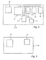
- Fig. 2 is a block diagram of the hardware in the monitoring unit 3.
- the monitoring unit 3 is supplied with power by a power connection 10.
- the monitoring unit 3 comprises a processing unit 11 which can be implemented by a commercially available microprocessor such as a CPU ("Central Processing Unit"), a DSP ("Digital Signal Processor") or another programmable logic device such as an FPGA, or alternatively as an ASIC ("Application-Specific Integrated Circuit”), as discrete analog and digital components, or in any combination thereof.
- a processing unit 11 which can be implemented by a commercially available microprocessor such as a CPU ("Central Processing Unit"), a DSP ("Digital Signal Processor") or another programmable logic device such as an FPGA, or alternatively as an ASIC ("Application-Specific Integrated Circuit"), as discrete analog and digital components, or in any combination thereof.
- the monitoring unit 3 can also comprise a communication unit 12.
- the communication unit 12 is arranged for wireless communication, for example with IR light, radio waves or ultrasound, with the remote arrangement 1.
- the communication unit 12 can also communicate with a door motor (not shown) to transmit information about the opening/closing state of the door arrangement.
- the monitoring unit 3 further comprises a photosensitive sensor 13, for example a two-dimensional CCD or a CMOS sensor, to record images.
- the sensor 13 is integrated on a printed circuit card and has an associated lens arrangement 14.
- the lens in the lens arrangement can for example have an aperture angle of 130 degrees.
- the monitoring unit 3 comprises a RAM memory 15.
- the monitoring unit 3 operates with a suitable operating system and can carry out advanced image processing.
- the monitoring unit 3 also comprises a permanent memory 16 for computer code and other data which has to be saved in a non-volatile memory.
- an indicator 17 for example in form of a light emitting diode, which is turned on or off to indicate the special function explained in more detail below.
- All the components included in the monitoring unit 3 can be integrated on one printed circuit card.
- the advantage of this is that the monitoring unit 3 becomes very stable, that is less sensitive to noise sources and having less points where sabotage and malfunction can occur.
- the algorithms for the function of the invention are stored in the permanent memory 16.
- Fig. 3 shows a block diagram of the remote arrangement 1.
- the remote arrangement can function similarly to a remote control of a TV receiver.
- the power supply for the remote arrangement 1 is obtained from a battery 20.
- the remote arrangement 1 comprises a transmitter 21.
- the transmitter 21 is arranged for wireless transmission of a signal, for example, using IR light, radio waves, or ultra sound, to the monitoring unit 3 and/or the marker 2.
- a cover 30 of the remote arrangement 1 is further shown in Fig. 4 and comprises a key set 31.
- the signal to the monitoring unit 3 comprises information about which key on the key set 31 is pressed by the person 8 carrying out the installation.
- the monitoring unit 3 is used to control the opening/closing of the sliding door 4, which can be seen in Fig. 1 .
- the sliding door 4 is to be opened when a person is approaching it, and closed when a person is moving away from it. There can be a large number of different criteria indicating when the sliding door 4 is to be opened/closed, such as the distance between the person and the sliding door 4 when opening is going to begin.
- the sensor 13 in the monitoring unit 3 is continuously recording images of a location in front of the sliding door. The recorded images are analyzed to decide whether a motion detection occurs and where in the image the motion detection occurs.
- Fig. 5 is a top plan view of a sliding door 40 above which a monitoring unit 3 is arranged.
- a first sub-location 41 and a second sub-location 42 are marked in the Figure.
- the sub-locations 41, 42 are not marked in the real environment but only illustrated in the Figure to facilitate the explanation.
- the sub-locations can be different depending on in what connection the monitoring unit is used and where the monitoring unit is arranged. When installing a monitoring unit it is always necessary to set up the sub-locations that apply to that particular application and place.
- the monitoring unit 3 will make a decision whether the sliding door is to be opened, closed, kept open or kept closed.
- the sub-locations 41, 42 are specified by four points 50, 51, 52, 53, which are shown in Fig. 5 for illustrative purposes and accordingly are only virtual and not marked on the base 7.
- said sub-locations are set up in such a manner that the monitoring unit 3 can make the right decision from the recorded images.
- the person making the installation does not need to have special knowledge to perform the installation, but the installation can be carried out essentially by any person after reading a short and simple manual.
- the key set 31 of the remote arrangement 1 is formed to correspond to the positions 50, 51, 52, 53.
- the key set 31 is thus formed according to a specific pattern showing in what places in relation to each other and in relation to the door arrangement the person carrying out the installation 8 is to place the marker 2 to set up the correct sub-locations in the monitoring unit 3.
- the dashed line 32 on the remote arrangement 1 marks the position of the door arrangement in relation to the points.
- the person carrying out the installation 8 first places the marker 2 in a first position 50 on the base 7.
- the person carrying out the installation wants this position 50 to mark a corner in the first sub-location 41.
- the illumination of the monitored location is advantageously subdued. Outdoors, one can place oneself so as to shade the marker 2 from direct sunlight.
- the person 8 carrying out the installation pushes a key 33 on the key set 31 of the remote arrangement 1.
- the lamp 5 of the marker can be switched on and give light or flash during the whole installation. The lamp can also be activated when pushing the key by the remote arrangement 1 transmitting a signal about activating the lamp to the marker 2.
- a signal is transmitted to the monitoring unit 3, the signal comprising information about what point 50 in the sub-location is going to be set.
- the monitoring unit 3 records an image and finds by image processing a white point against a black background in the image. A difference image is calculated between two images recorded adjacent in time. A maximum in the image is calculated and the coordinates for this maximum correspond to the point for the marker in the image.
- the detected coordinates for the marker are stored both in the RAM memory 15 to be able to be used directly and in the permanent memory 16 so that the coordinates will be stored even if the monitoring unit is turned off for a while.
- the next position on the base 7 can now be recorded.
- the person 8 carrying out the installation moves the marker 2 to a new selected position on the base. Once again he pushes a key 32 on the remote arrangement 1.
- a second point 51 in the image is recorded and its coordinates are stored. The same procedure is used to record the remaining positions 52, 53.
- the monitoring unit 3 now has enough information to divide the image into different sub-locations 41, 42 within which different rules apply.
- the monitoring unit 3 can be arranged to connect recorded points with straight lines or to let the locations around the door arrangement form semicircles. Also other patterns and figures are possible.
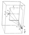
- a second embodiment is shown in Fig. 6 and the monitoring unit works in a similar way as described above with reference to Fig. 5 .
- the remote arrangement can work as described above with reference to Fig. 3 and Fig. 4 except for the marker which is now integrated with the remote arrangement as shown in Fig. 6 .
- the remote arrangement 60 can be an ordinary remote control of the type as used for TV receivers.
- the remote arrangement 60 itself is placed on or held against the base.
- the remote arrangement 60 transmits a signal by means of an IR transmitter 65 to a monitoring unit 61 with IR pulses.
- the IR transmitter 65 can advantageously be realized as a commercially available light emitting diode (LED) with a wavelength in the infrared part of the spectrum.
- LED light emitting diode
- the monitoring unit 61 receives the signal by means of an IR receiver 64.
- the monitoring unit 61 is also in this embodiment arranged to control the opening/closing of a sliding door 62.
- the same IR transmitter 65 used to transmit a signal to the monitoring unit 61 can be used as a "lamp" since the photosensitive sensor 67 is also sensitive to IR light.
- the remote arrangement 60 will thus at the same time be a marker. Pushing a key on the key set 66 of the remote arrangement 60 results in the fact that IR light is pulsed out from the remote arrangement 60 at a specified frequency in a pulse train. Different key pushings result in different pulse trains. If a key on the remote arrangement 60 is kept pushed in, a pulse train is repeated at a specified interval, for example of 30 ms.
- a person carrying out the installation places the monitoring unit 61 at a certain location and pushes a key on the key set 66, which key corresponds to a point which partly specifies a desired sub-location 63.
- An IR pulse train is transmitted to the monitoring unit 61.
- the monitoring unit 61 receives the signal by means of the IR receiver 64 as decoder.
- the IR signal contains information about which position in Fig. 5 corresponds to the detection.
- the monitoring unit 61 records an image sequence using a photosensitive sensor 67. The monitoring unit 61 detects where in the recorded image the remote arrangement 60 is to be found.
- the IR pulse train is sent at intervals, for example of 30 ms, and will therefore flash in the recorded images.
- the difference between two images recorded adjacent in time is calculated. Since the IR light flashes, sometimes a light is recorded and sometimes no light is recorded.
- the difference image detects this flashing and in this way the position of the remote arrangement 60 in the image is obtained.
- the coordinates can in this way be calculated and stored to be used when the monitoring unit 61 is used in its normal function.
- the person carrying out the installation can move the remote arrangement 60 and push another key to record the next point specifying desired sub-location 63.
- the person carrying out the installation can also, instead of marking separate positions, "draw" the desired sub-location, such as a threshold, by following the delimitation of the desired sub-location using the remote arrangement.
- the photosensitive sensor 13 records continuously images and detects the position of the remote arrangement in every image. In that way the desired sub-location is set up in the monitoring unit.
- the remote arrangement 1, according to the first embodiment can be arranged to transmit a signal to the marker 2.
- This signal contains information about at what frequency the lamp 4 will flash when it emits light.
- the monitoring unit 3 has information about what flashing frequencies represent the respective points on the base 7. In this case there is no need for the remote arrangement to send any signal to the monitoring unit. Instead the monitoring unit 3 can be set in a specified on-position, which implies that the monitoring unit seeks out light points and calculates their flashing frequency in order to determine in this way what point in a sub-location they represent. It is also possible to have solely a lamp which can be set up at different flashing frequencies. A separate remote arrangement is then unnecessary.
- the recording of the point can also be slightly delayed, so that the person carrying out the installation first pushes a specified key on the remote arrangement and then puts the remote arrangement in place. After a specified number of seconds after the key pushing, the remote arrangement transmits an IR pulse train and the monitoring unit records an image.
- the marker has a lamp shining with a fixed light.
- the monitoring unit 3 records an image and performs an image analysis of the image by performing a threshold operation, which results in an indication of how intense a possible detection is and where in the image it occurs.
- the lamp is placed on a base with a black tarnish surface, it is also possible to look for image points with high intensity close to image points with low intensity.
- this position is verified by adapting a white ellipse against a black background. This is done because due to perspective the shining circular point effects appears as an ellipse in the image.
- the remote arrangement can be used in a large number of applications by installation of monitoring units and sensors, in which the monitored location is to be divided into different sub-locations. Different kinds of software in the monitoring unit can control how recorded points/positions are to divide a location and what the function will be in these sub-locations.
- the monitoring unit can for example be used in burglar surveillance.
- the remote arrangement does not need a key set formed according to a specific pattern, but the monitoring unit can be arranged to connect recorded points according to a specific scheme which among other things can be dependent on the order in which the points are recorded or the distance between different points. For example, adjacent points can be linked with each other in order to create a location in the image.
- the monitoring unit 3, 61 can be provided with an indication element 9, as shown in Figs. 1 and 6 .
- the indication element 9 can for example be a light emitting diode turned on when the remote arrangement 1, 60 transmits a signal to the monitoring unite 3, 61 and turned off when the monitoring unit 3, 61 has found the position of the coordinates of the marker 2, 60 in a recorded image.
Landscapes
- Physics & Mathematics (AREA)
- General Physics & Mathematics (AREA)
- Engineering & Computer Science (AREA)
- Computer Vision & Pattern Recognition (AREA)
- Human Computer Interaction (AREA)
- Alarm Systems (AREA)
- Burglar Alarm Systems (AREA)
- Control Or Security For Electrophotography (AREA)
- Closed-Circuit Television Systems (AREA)
- Spinning Or Twisting Of Yarns (AREA)
Abstract
Description
- This invention relates to a method and a system for installation of a monitoring unit incorporated in the system. The monitoring unit comprises a photosensitive sensor for recording images of a monitored location. The invention also relates to a computer program product.
- Different types of monitoring system with photosensitive sensors (digital cameras) are used today in different applications such as burglary surveillance. The sensor records images of a location that is to be monitored.
- The monitored location may be divided into different sub-locations within which different functions and criteria apply. These sub-locations can be defined by one or more coordinates in the image. The appearance and function of the sub-locations is different from place to place and from application to application. These sub-locations can, for example, in monitoring be used to mark doors through which persons are expected to enter.
- Today there are different methods to set the coordinates for different sub-locations. For example, preselected values can be used, but a problem is that the parameters cannot be changed to adapt the image processing algorithms to the current installation/placement of the sensor. This implies that the monitoring system must be located in a predetermined way. If this is not accomplished, the performance of the system is reduced.
- Another way is to supply the monitoring system with a switch or a keyboard, which can be set in a number of positions which define different predetermined sub-locations. A disadvantage of this technique is that the switch can only be set in a limited number of positions. Additionally it is necessary to measure, for example, a distance to set the system. This can be complicated and time-consuming and less accuracte.
- Another way is to connect the monitoring system to a computer which is in direct communication with a calculating unit that processes the images recorded by the sensor. This computer can comprise a display on which an image recorded by the sensor is shown. Furthermore, the computer can be provided with special computer software which enables the person carrying out the installation to draw different sub-locations in the recorded image shown on the display. A disadvantage of this solution is that it requires special and advanced computer equipment and knowledge of the functions of the equipment in order to enable the person carrying out the installation to install a monitoring system. It also requires special communication interfaces and contacts to connect the computer to the system, which causes extra installation work and increased costs. Further it can be difficult in practice to exactly mark intended positions on the display, for example with a mouse, for instance due to insufficient contrast or inexact rendition on the display.
- Published European Patent Application No.
EP 0736837A2 discloses a infrared transmitter and receiver, making possible to control a cursor at a monitor. The transmitter has two IR senders and the receiver has two IR receivers arranged ortogonally in relation to the senders. By tilting the IR senders, the two receivers obtain different signal strength, and the direction of the sender can be calculated to move the cursor to the calculated position on the monitor. - European Patent No.
EP 0126955B1 discloses a video surveillance system in which the suveillance area is divided in sections by distinct markings arranged at the ground. The markings have different degrees of gray to be able to be distinguished from gray objects passing the markings. One marking has vertical surfaces in order not to be covered by snow or similar. - The
US patent 5,097,328 relates to a remote sensing system which includes one or more video cameras which captures successive images of the area to be monitored. Sub-areas of interest in the image are defined by selectively illuminating each of the sub-areas during an initiation phase. During operation the system analyzes pixel data only from the defined sub-areas. During the initiation phase a bright light is placed in the center of the appropriate position and the image system grabs an image from the camera and determines the position in the image of the digitized pixels which have values consistent with a bright light. Alternatively, in order to define the sub-area the operator moves a bright light around in the area to be defined, while the image subsystem continually grab images. The captured maximum X coordinate and the captured maximum Y coordinate excursions of the bright light define the limiting coordinates of the sub-area. - The German patent application
0,126,955 relates to an open-air ground surveillance apparatus comprising a strip of ground which is to be monitored and comprising poles which are erected along the strip of ground and serve to support illuminators and television cameras which are connected to an image analysing device. The strip of ground comprises at least three control strips, which are aligned parallel to one another and each of which has a different grey value, and that the illuminators and television cameras which are assigned to one and the same region of ground strip are supported several metres above the control strip. - The international patent application
WO 01/49033 - An object of the invention is therefore to solve the problems described above and thus provide a system for installation of a monitoring unit, and a method for installation of a monitoring unit which in a simple way can perform a correct and optimal installation of a monitoring unit comprising a photosensitive sensor.
- The invention concerns, according to a first aspect, a system for installation of a monitoring unit, comprising a photosensitive sensor for recording images of a monitored location. The system comprises a light emitting element including a lamp or an IR transmitter. The monitoring unit is arranged to detect, during installation, the position of the light emitting element in a recorded image and by means of said position define a sub-location within the monitored area.
- The monitoring unit further comprises a receiver distinct from the photosensitive sensor, for receiving a signal comprising information identifying the position. The information pertains to what type of pattern the position defines, wherein the pattern reflects the shape of the sub-location.
- The detected position can represent a point or a pixel in the recorded image. The coordinates of the point in the recorded image can be determined to define the position. The position can constitute a point in a larger pattern. The position can wholly or partly define a sub-location within the monitored area or location. The sub-location can also be a line separating, for instance, one part of the monitored location from another. The sub-locations can also be a single position or a point that is to be monitored. This is suitable, for example, if it is desired to monitor a button or a mark.
- A sub-location can essentially have any desired shape to divide the monitored location. For example, the sub-location can be circular, and a detected position can indicate the center of the circular location. The extension of the circular location can be predetermined but can also be defined by detecting an additional position, which indicates the radius of the circular location. The sub-location can also be rectangular and be defined by four positions in the respective corners of the rectangle. Alternatively the rectangular location can be defined by two positions located in two corners diagonally to each other in the rectangle.
- A sub-location can thus be defined by one or more positions. In principle, any number of positions can be detected. A person carrying out the installation can, with the light emitting element, draw a line or the limitation of a sub-location in physical reality, which then is detected by the monitoring unit.
- With an increased number of positions a specific and unique configuration of a desired sub-location may be defined. In some cases, only a simple division of the monitored location is needed and consequently the installation can be performed quickly.
- The different sub-locations can be associated with different functions. For example, in one sub-location a moving object can be allowed and movement detection is allowed in this location but in another sub-location no such object is allowed and movement detection in this location will cause an alarm.
- The light emitting element can be an ordinary lamp, for example a flashlight. An advantage of the very simple light emitting element is that the system will be easy to implement and thus cost-effective. The system is also easy for a user to utilize.
- Another advantage of the system is that it can be used in different applications. The setting of sub-locations can be desirable in many situations, for example, in automatic door openers and in burglary surveillance. It is possible to use the same equipment for all these types of installations.
- One thing that separates the different applications is the function in the different sub-locations when the monitoring unit is operating. An advantage of the invention is that a person carrying out the installation does not need to have special knowledge to install the monitoring unit for different applications. This enables quicker and easier assembly and installation and, as a result, the costs for installation are reduced.
- Another advantage of the system is that the definition of the sub-location will be more exact since the definition of the desired sub-location in the monitored location can be made in physical reality and transferred to the "the image world" of the monitoring unit. The word "image world" means how the monitoring unit perceives the physical reality. This causes the monitoring unit in operation to carry out a more thorough analysis of a recorded image, which in turn causes the monitoring result to be more secure and more reliable.
- The monitoring unit further comprises means for receiving a signal containing information which identifies or qualifies' said position.
- The signal contain information about what type of pattern the position defines. The pattern reflects the shape of a sub-location. If a pattern is defined by several points, the signal can contain information about to what point in the pattern the current position relates.
- The monitoring unit can initially possess information about what pattern is to be created, and the information received by the signal can contain information about to what point in this pattern a detected position corresponds.
- An advantage of the receiving the signal containing this information is that the monitoring unit quickly and unambiguously receives information about how the detected position is to be interpreted. The monitoring unit does not need to guess or calculate what pattern the position represents, thus saving processor power.
- The light emitting element can, in addition to marking a position in the image, also have the function of transferring information about the meaning of the detected position. This information can, for example, be transferred by flashing the light emitting element at a certain frequency or a determined number of times, which is recorded by the photosensitive sensor.
- In one embodiment the system comprises a remote device comprising a means for sending, which is arranged to emit said signal to the monitoring unit, which signal comprises information identifying said position.
- The remote device can be arranged as a conventional remote control, for example, to control a television receiver This allows a simple and conventional construction. The same remote device can be used for different applications, which results in lower manufacturing cost. This makes it easy for the person carrying out the installation, who can easily install monitoring units for different applications without having to learn application specific characteristics. The remote device can also be used to control the normal function of the monitoring unit.
- In one embodiment, the remote device comprises a key set, each key in the key set being associated with a determined position.
- Different keys in the key set can identify different positions. An advantage of the key set is that it will be easy for the person carrying out the installation to specify what position is to be detected by the monitoring unit by pushing one single key. The remote device is also simple to use.
- In another embodiment, the key set is formed according to a specified pattern representing a sub-location of the monitored location, a key in the key set corresponding to a specified position with which the sub-location can be defined.
- By forming the key set in this way, a person carrying out the installation can receive visual assistance to find out what positions are to be detected to set up a specific sub-location. The person carrying out the installation receives in this way information about which and how many positions need be detected for a specific sub-location. This makes the installation easier and quicker.
- The blight emitting element can be arranged on the remote device. An advantage of this :is that there is no need for an extra, separate unit for the light emitting element. This simplifies the construction. The use of the system also becomes simpler. Additionally the cost for the system becomes lower by integrating two separate units.
- In another embodiment of the system, the light emitting element and the means for sending constitute one and the same component.
- An integration of the light emitting element and the means for sending results in simpler and more flexible construction, since there is no need for any extra equipment for the light emitting element. By also using the means for sending as the light emitting element, a double function is achieved. This decreases the cost of the system.
- In one embodiment of the system, said component is a light emitting diode, for example of IR type.
- The photosensitive sensor can record IR light and is thus able to detect the position in the recorded image. The means for receiving a signal can be an IR receiver receiving the signal with information.
- In one embodiment, the monitoring unit is further provided with a memory arranged to store said detected position for later use in a control program.
- The position is stored in a RAM memory to be used directly to specify a sub-location. The position is advantageously also stored in a non-volatile memory to be able to reuse the position even if the monitoring unit for example is turned off.
- There is also disclosed a device for installation of a monitoring unit comprising a photosensitive sensor for recording images of a monitored location. The device comprising a means for sending, which is arranged to emit a signal containing information identifying a position in a recorded image, which position specifies a sub-location within the monitored location.
- Advantages of the arrangement have essentially been indicated above in the description of the system.
- There is also disclosed a monitoring unit comprising a photosensitive sensor arranged to record images of a monitored location. The monitoring unit comprises a processing unit arranged to detect the position of a light emitting element in a recorded image and by means of this position specify a sub-location of the monitored location.
- Advantages of the monitoring unit have essentially been indicated above in the description of the system.
- According to a second aspect, the invention relates to a method for installation of a monitoring unit comprising a photosensitive sensor for recording images of a monitored location. The method comprises the steps of recording at least one image of the monitored location and in the recorded image detecting the position of a light emitting element including a lamp or an IR transmitter and by means of this position specifying a sub-location of the monitored location. The monitoring unit further comprises a receiver, distinct from the photosensitive sensor, which receives a signal containing information identifying the position. The information pertains to what type of pattern the position defines, wherein the pattern reflects the shape of the sub-location.
- The method has: essentially the same advantages as the above described system.
- In one embodiment of the method, the light emitting element is placed in turns at a number of different places. The positions of the light emitting element which are detected in each recorded image are used together to determine said sub-location.
- According to a third aspect, the invention relates to a computer program product including program code, which when input in a memory and executed by a processor executes the method as described above.
- The computer program product has essentially the same advantages as the above described system.
- There is also disclosed use of a remote arrangement for installation of a monitoring unit according to the method described above.
- The use of a remote arrangement has essentially the same advantages as the above described system.
- Further objects, features and advantages of the invention will appear from the following detailed description of embodiments of the invention with reference to the accompanying drawings, in which:
-
Fig. 1 is a perspective view of a system according to a first embodiment of the present invention. -
Fig. 2 is a block diagram of a monitoring unit included in the system according toFig. 1 . -
Fig. 3 is a block diagram of a remote arrangement included in the system according toFig. 1 . -
Fig. 4 is a plan view of a remote arrangement with a key set according to one embodiment of the present invention. -
Fig. 5 is a plan view of a door arrangement with different sub-locations marked. -
Fig. 6 is a perspective view of a system according to a second embodiment of the present invention. -
Fig. 1 is a perspective view of the system for installation according to the first embodiment. The system comprises aremote arrangement 1 sending a signal containing information regarding the position of amarker 2 on abase 7 to amonitoring unit 3. - The
marker 2 may comprise alamp 5 with an intense circular point-source light, such as a light emitting diode. Thelamp 5 can be mounted on top of abox 6 provided with a matt black tarnish surface surrounding the lamp. The lamp blinks with a predetermined frequency which can be 2 times per second. Thebox 6 is formed with a flat side so that a person carrying out the installation can put it on thebase 7 in order to mark a position. Aperson 8 carrying out the installation controls theremote arrangement 1 and moves themarker 2 to different positions on thebase 7. - The
monitoring unit 3 is arranged above a door arrangement 4 and controls opening/closing of the same. The door arrangement 4 is in this case a sliding door. -
Fig. 2 is a block diagram of the hardware in themonitoring unit 3. Themonitoring unit 3 is supplied with power by apower connection 10. Further themonitoring unit 3 comprises aprocessing unit 11 which can be implemented by a commercially available microprocessor such as a CPU ("Central Processing Unit"), a DSP ("Digital Signal Processor") or another programmable logic device such as an FPGA, or alternatively as an ASIC ("Application-Specific Integrated Circuit"), as discrete analog and digital components, or in any combination thereof. - The
monitoring unit 3 can also comprise acommunication unit 12. Thecommunication unit 12 is arranged for wireless communication, for example with IR light, radio waves or ultrasound, with theremote arrangement 1. Thecommunication unit 12 can also communicate with a door motor (not shown) to transmit information about the opening/closing state of the door arrangement. - The
monitoring unit 3 further comprises aphotosensitive sensor 13, for example a two-dimensional CCD or a CMOS sensor, to record images. Thesensor 13 is integrated on a printed circuit card and has an associatedlens arrangement 14. The lens in the lens arrangement can for example have an aperture angle of 130 degrees. - Moreover, the
monitoring unit 3 comprises aRAM memory 15. Themonitoring unit 3 operates with a suitable operating system and can carry out advanced image processing. Themonitoring unit 3 also comprises apermanent memory 16 for computer code and other data which has to be saved in a non-volatile memory. In addition there can be an indicator 17, for example in form of a light emitting diode, which is turned on or off to indicate the special function explained in more detail below. - All the components included in the
monitoring unit 3 can be integrated on one printed circuit card. The advantage of this is that themonitoring unit 3 becomes very stable, that is less sensitive to noise sources and having less points where sabotage and malfunction can occur. - The algorithms for the function of the invention are stored in the
permanent memory 16. -
Fig. 3 shows a block diagram of theremote arrangement 1. The remote arrangement can function similarly to a remote control of a TV receiver. The power supply for theremote arrangement 1 is obtained from abattery 20. Further, theremote arrangement 1 comprises atransmitter 21. Thetransmitter 21 is arranged for wireless transmission of a signal, for example, using IR light, radio waves, or ultra sound, to themonitoring unit 3 and/or themarker 2. - A
cover 30 of theremote arrangement 1 is further shown inFig. 4 and comprises akey set 31. The signal to themonitoring unit 3 comprises information about which key on the key set 31 is pressed by theperson 8 carrying out the installation. - In the first embodiment, the
monitoring unit 3 is used to control the opening/closing of the sliding door 4, which can be seen inFig. 1 . The sliding door 4 is to be opened when a person is approaching it, and closed when a person is moving away from it. There can be a large number of different criteria indicating when the sliding door 4 is to be opened/closed, such as the distance between the person and the sliding door 4 when opening is going to begin. To control opening/closing, thesensor 13 in themonitoring unit 3 is continuously recording images of a location in front of the sliding door. The recorded images are analyzed to decide whether a motion detection occurs and where in the image the motion detection occurs. -
Fig. 5 is a top plan view of a slidingdoor 40 above which amonitoring unit 3 is arranged. Afirst sub-location 41 and asecond sub-location 42 are marked in the Figure. The sub-locations 41, 42 are not marked in the real environment but only illustrated in the Figure to facilitate the explanation. The sub-locations can be different depending on in what connection the monitoring unit is used and where the monitoring unit is arranged. When installing a monitoring unit it is always necessary to set up the sub-locations that apply to that particular application and place. - Depending on in what sub-locations 41, 42 motion detection occurs the
monitoring unit 3 will make a decision whether the sliding door is to be opened, closed, kept open or kept closed. - The sub-locations 41, 42 are specified by four
points Fig. 5 for illustrative purposes and accordingly are only virtual and not marked on thebase 7. - When installing of the
monitoring unit 3, said sub-locations are set up in such a manner that themonitoring unit 3 can make the right decision from the recorded images. The person making the installation does not need to have special knowledge to perform the installation, but the installation can be carried out essentially by any person after reading a short and simple manual. - To simplify the installation, the key set 31 of the
remote arrangement 1 is formed to correspond to thepositions installation 8 is to place themarker 2 to set up the correct sub-locations in themonitoring unit 3. The dashedline 32 on theremote arrangement 1 marks the position of the door arrangement in relation to the points. - The person carrying out the
installation 8 first places themarker 2 in afirst position 50 on thebase 7. The person carrying out the installation wants thisposition 50 to mark a corner in thefirst sub-location 41. To simplify the detection of the marker, the illumination of the monitored location is advantageously subdued. Outdoors, one can place oneself so as to shade themarker 2 from direct sunlight. After themarker 2 has been placed, theperson 8 carrying out the installation pushes a key 33 on the key set 31 of theremote arrangement 1. Thelamp 5 of the marker can be switched on and give light or flash during the whole installation. The lamp can also be activated when pushing the key by theremote arrangement 1 transmitting a signal about activating the lamp to themarker 2. - When the person carrying out the installation pushes the key 33, a signal is transmitted to the
monitoring unit 3, the signal comprising information about whatpoint 50 in the sub-location is going to be set. Themonitoring unit 3 records an image and finds by image processing a white point against a black background in the image. A difference image is calculated between two images recorded adjacent in time. A maximum in the image is calculated and the coordinates for this maximum correspond to the point for the marker in the image. - The detected coordinates for the marker are stored both in the
RAM memory 15 to be able to be used directly and in thepermanent memory 16 so that the coordinates will be stored even if the monitoring unit is turned off for a while. - The next position on the
base 7 can now be recorded. Theperson 8 carrying out the installation moves themarker 2 to a new selected position on the base. Once again he pushes a key 32 on theremote arrangement 1. Asecond point 51 in the image is recorded and its coordinates are stored. The same procedure is used to record the remainingpositions - The
monitoring unit 3 now has enough information to divide the image intodifferent sub-locations - The
monitoring unit 3 can be arranged to connect recorded points with straight lines or to let the locations around the door arrangement form semicircles. Also other patterns and figures are possible. - A second embodiment is shown in
Fig. 6 and the monitoring unit works in a similar way as described above with reference toFig. 5 . Also the remote arrangement can work as described above with reference toFig. 3 andFig. 4 except for the marker which is now integrated with the remote arrangement as shown inFig. 6 . Theremote arrangement 60 can be an ordinary remote control of the type as used for TV receivers. Theremote arrangement 60 itself is placed on or held against the base. Theremote arrangement 60 transmits a signal by means of anIR transmitter 65 to amonitoring unit 61 with IR pulses. TheIR transmitter 65 can advantageously be realized as a commercially available light emitting diode (LED) with a wavelength in the infrared part of the spectrum. - The
monitoring unit 61 receives the signal by means of anIR receiver 64. Themonitoring unit 61 is also in this embodiment arranged to control the opening/closing of a slidingdoor 62. Thesame IR transmitter 65 used to transmit a signal to themonitoring unit 61 can be used as a "lamp" since thephotosensitive sensor 67 is also sensitive to IR light. - The
remote arrangement 60 will thus at the same time be a marker. Pushing a key on the key set 66 of theremote arrangement 60 results in the fact that IR light is pulsed out from theremote arrangement 60 at a specified frequency in a pulse train. Different key pushings result in different pulse trains. If a key on theremote arrangement 60 is kept pushed in, a pulse train is repeated at a specified interval, for example of 30 ms. - By setting up a
sub-location 63, a person carrying out the installation places themonitoring unit 61 at a certain location and pushes a key on the key set 66, which key corresponds to a point which partly specifies a desiredsub-location 63. An IR pulse train is transmitted to themonitoring unit 61. Themonitoring unit 61 receives the signal by means of theIR receiver 64 as decoder. The IR signal contains information about which position inFig. 5 corresponds to the detection. In response to the signal, themonitoring unit 61 records an image sequence using aphotosensitive sensor 67. Themonitoring unit 61 detects where in the recorded image theremote arrangement 60 is to be found. The IR pulse train is sent at intervals, for example of 30 ms, and will therefore flash in the recorded images. The difference between two images recorded adjacent in time is calculated. Since the IR light flashes, sometimes a light is recorded and sometimes no light is recorded. The difference image detects this flashing and in this way the position of theremote arrangement 60 in the image is obtained. The coordinates can in this way be calculated and stored to be used when themonitoring unit 61 is used in its normal function. - When the
monitoring unit 61 has calculated and stored the coordinates for this point, the person carrying out the installation can move theremote arrangement 60 and push another key to record the next point specifying desiredsub-location 63. - The person carrying out the installation can also, instead of marking separate positions, "draw" the desired sub-location, such as a threshold, by following the delimitation of the desired sub-location using the remote arrangement. The
photosensitive sensor 13 records continuously images and detects the position of the remote arrangement in every image. In that way the desired sub-location is set up in the monitoring unit. - In an:alternative embodiment, the
remote arrangement 1, according to the first embodiment, can be arranged to transmit a signal to themarker 2. This signal contains information about at what frequency the lamp 4 will flash when it emits light. Themonitoring unit 3 has information about what flashing frequencies represent the respective points on thebase 7. In this case there is no need for the remote arrangement to send any signal to the monitoring unit. Instead the monitoringunit 3 can be set in a specified on-position, which implies that the monitoring unit seeks out light points and calculates their flashing frequency in order to determine in this way what point in a sub-location they represent. It is also possible to have solely a lamp which can be set up at different flashing frequencies. A separate remote arrangement is then unnecessary. - In a further example, the recording of the point can also be slightly delayed, so that the person carrying out the installation first pushes a specified key on the remote arrangement and then puts the remote arrangement in place. After a specified number of seconds after the key pushing, the remote arrangement transmits an IR pulse train and the monitoring unit records an image.
- Another alternative is that the marker has a lamp shining with a fixed light. The
monitoring unit 3 records an image and performs an image analysis of the image by performing a threshold operation, which results in an indication of how intense a possible detection is and where in the image it occurs. - If the lamp is placed on a base with a black tarnish surface, it is also possible to look for image points with high intensity close to image points with low intensity. When a possible position for the marker has been calculated, this position is verified by adapting a white ellipse against a black background. This is done because due to perspective the shining circular point effects appears as an ellipse in the image.
- The remote arrangement can be used in a large number of applications by installation of monitoring units and sensors, in which the monitored location is to be divided into different sub-locations. Different kinds of software in the monitoring unit can control how recorded points/positions are to divide a location and what the function will be in these sub-locations. The monitoring unit can for example be used in burglar surveillance.
- Alternatively, the remote arrangement does not need a key set formed according to a specific pattern, but the monitoring unit can be arranged to connect recorded points according to a specific scheme which among other things can be dependent on the order in which the points are recorded or the distance between different points. For example, adjacent points can be linked with each other in order to create a location in the image.
- The
monitoring unit Figs. 1 and6 . The indication element 9 can for example be a light emitting diode turned on when theremote arrangement monitoring unite monitoring unit marker - It is obvious that many modifications of the above described embodiments of the invention are possible within the scope of the invention specified by the appended claims.
Claims (17)
- A system for installation of a monitoring unit (3, 61), said system comprising a monitoring unit (3, 61) and a light emitting element (2) including a lamp (5) or an IR transmitter (65), said monitoring unit (3, 61) comprising a photosensitive sensor (13, 67) for recording images of a monitored area (7) wherein the monitoring unit (3, 61) is arranged to detect the position of the light emitting element (2) in an image to be recorded and by means of said position specify a sub-location (41, 42, 63) within the monitored area (7),
characterized in that
the monitoring unit (3, 61) further comprises a receiver (64), distinct from said photosensitive sensor (13, 67), for receiving a signal comprising information identifying said position, said information pertaining to what type of pattern the position defines, and wherein said pattern reflects the shape of said sub-location (41, 42, 63). - The system according to claim 1, where in a case said pattern is defined by several points (50, 51, 52, 53), said information pertains to what point (50, 51, 52, 53) in said pattern a current position relates to.
- The system according to any one of the preceding claims, further comprising a remote arrangement (1, 60) comprising a means (65) for sending, which is arranged to emit said signal to the monitoring unit (3, 61), which signal comprises information identifying said position.
- The system according to claim 3, wherein the remote arrangement (1, 60) further comprises a key set (31, 66), each key (33, 34, 35, 36) in the key set (31, 66) being associated with a determined position.
- The system according to claim 4, wherein the key set (31, 66) is formed according to a determined pattern representing a sub-location (41, 42, 63) of the monitored location (7), a key (33, 34, 35, 36) in the key set (31, 66) corresponding to a determined position by means of which the sub-location (41, 42, 63) is specified.
- The system according to any one of claims 3-5, wherein the light emitting element (2) is integrated with the remote arrangement (1, 60).
- The system according to claim 6, wherein the light emitting element (2) and said means (65) for sending consist one and the same component.
- The system according to claim 7, wherein said component is a light emitting diode, particularly an IR light emitting diode.
- The system according to any one of the preceding claims, wherein the monitoring unit (3, 61) further comprises a memory (15, 16) arranged to store said detected position for later use in a control program.
- The system according to any one of the preceding claims, wherein the light emitting element (2) is moveable in the monitored location (7).
- The system according to any one of the preceding claims, wherein the monitoring unit (3, 61) further comprises an indication element (9, 17) indicating that the position of the light emitting element (2) is detected.
- A method for installation of a monitoring unit (3, 61) comprising a photosensitive sensor (13, 67) arranged to record images of a monitored area (7), comprising: recording at least one image of the monitored area (7) and in the recorded image detecting the position of a light emitting element (2) including a lamp (5) or an IR transmitter (65) included therein and by means of said position specifying a sub-location (41, 42, 63) of the monitored area (7),
characterized in that
the monitoring unit (3, 61) further comprises a receiver (64), distinct from said photosensitive sensor (13, 67), which receives a signal containing information identifying said position, said information pertaining to what type of pattern the position defines, and wherein said pattern reflects the shape of said sub-location (41, 42, 63). - The method according to claim 12, further comprising:storing said position for later use in a control program.
- The method according to claim 12 or 13, further comprising: indicating that the position of the light emitting element (2) is detected.
- The method according to any one of claims 12-14, further comprising: placing a light emitting element (2) at a position, which contributes to specifying the sub-location (41, 42, 63) within the monitored area (7).
- The method according to claim 15, wherein the light emitting element (2) in turns is placed at different positions and wherein the positions of the light emitting element (2)detected in each recorded image are used together to specify said sub-location (41, 42, 63).
- A computer program product comprising program code, which when input in a memory (15, 16) and executed by a processor (11) executes the method according to any one of claims 12-16.
Applications Claiming Priority (3)
| Application Number | Priority Date | Filing Date | Title |
|---|---|---|---|
| SE0103225A SE523456C2 (en) | 2001-09-28 | 2001-09-28 | System, device and method for setting up a monitoring unit |
| SE0103225 | 2001-09-28 | ||
| PCT/SE2002/001753 WO2003027977A1 (en) | 2001-09-28 | 2002-09-26 | Method and system for installation of a monitoring unit |
Publications (2)
| Publication Number | Publication Date |
|---|---|
| EP1438698A1 EP1438698A1 (en) | 2004-07-21 |
| EP1438698B1 true EP1438698B1 (en) | 2010-11-17 |
Family
ID=20285471
Family Applications (1)
| Application Number | Title | Priority Date | Filing Date |
|---|---|---|---|
| EP02773099A Expired - Lifetime EP1438698B1 (en) | 2001-09-28 | 2002-09-26 | Method and system for installation of a monitoring unit |
Country Status (6)
| Country | Link |
|---|---|
| EP (1) | EP1438698B1 (en) |
| AT (1) | ATE488826T1 (en) |
| DE (1) | DE60238344D1 (en) |
| ES (1) | ES2355549T3 (en) |
| SE (1) | SE523456C2 (en) |
| WO (1) | WO2003027977A1 (en) |
Families Citing this family (3)
| Publication number | Priority date | Publication date | Assignee | Title |
|---|---|---|---|---|
| SE0203483D0 (en) | 2002-11-21 | 2002-11-21 | Wespot Ab | Method and device for fall detection |
| US8508372B2 (en) * | 2010-06-21 | 2013-08-13 | General Electric Company | Method and system for fall detection |
| CN103306592A (en) * | 2012-03-08 | 2013-09-18 | 鸿富锦精密工业(深圳)有限公司 | Safety reminding system and safety reminding method |
Family Cites Families (6)
| Publication number | Priority date | Publication date | Assignee | Title |
|---|---|---|---|---|
| DE3316122A1 (en) * | 1983-05-03 | 1984-11-08 | Kraftwerk Union AG, 4330 Mülheim | OUTDOOR AREA MONITORING SYSTEM |
| US5097328A (en) * | 1990-10-16 | 1992-03-17 | Boyette Robert B | Apparatus and a method for sensing events from a remote location |
| KR0150700B1 (en) * | 1995-04-06 | 1998-11-02 | 구자홍 | Point type wireless controller using infrared rays |
| NO982640L (en) * | 1998-06-08 | 1999-12-09 | Nyfotek As | Method and system for monitoring an area |
| US7042492B2 (en) * | 1999-12-10 | 2006-05-09 | The Stanley Works | Automatic door assembly with video imaging device |
| WO2001071688A1 (en) * | 2000-03-20 | 2001-09-27 | Qualisys Digital Media Ab | Monitoring system |
-
2001
- 2001-09-28 SE SE0103225A patent/SE523456C2/en not_active IP Right Cessation
-
2002
- 2002-09-26 EP EP02773099A patent/EP1438698B1/en not_active Expired - Lifetime
- 2002-09-26 AT AT02773099T patent/ATE488826T1/en not_active IP Right Cessation
- 2002-09-26 WO PCT/SE2002/001753 patent/WO2003027977A1/en not_active Ceased
- 2002-09-26 ES ES02773099T patent/ES2355549T3/en not_active Expired - Lifetime
- 2002-09-26 DE DE60238344T patent/DE60238344D1/en not_active Expired - Lifetime
Also Published As
| Publication number | Publication date |
|---|---|
| ES2355549T3 (en) | 2011-03-28 |
| EP1438698A1 (en) | 2004-07-21 |
| SE523456C2 (en) | 2004-04-20 |
| SE0103225L (en) | 2003-03-29 |
| WO2003027977A1 (en) | 2003-04-03 |
| SE0103225D0 (en) | 2001-09-28 |
| ATE488826T1 (en) | 2010-12-15 |
| DE60238344D1 (en) | 2010-12-30 |
Similar Documents
| Publication | Publication Date | Title |
|---|---|---|
| US7230538B2 (en) | Apparatus and method for identifying surrounding environment by means of image processing and for outputting the results | |
| EP1279150B1 (en) | Surveillance system with camera | |
| EP2564380B1 (en) | Method and system for security system tampering detection | |
| EP2801958B1 (en) | Monitoring method and camera | |
| US7136513B2 (en) | Security identification system | |
| US7193608B2 (en) | Collaborative pointing devices | |
| US7302080B2 (en) | System for installation | |
| CN101563193B (en) | Method of controlling an autonomous device | |
| AU2000241410A1 (en) | Surveillance system with camera | |
| EP3762906B1 (en) | System and method for preventing false alarms due to display images | |
| KR20170058827A (en) | Security system and security process and security controller of throw trash, by detected humans action or shape image | |
| GB2368482A (en) | Pose-dependent viewing system | |
| CN104994302A (en) | Swimming pool directional wireless signal trigger based on RFID technology | |
| KR100457929B1 (en) | System of Soft Remote Controller Using Hand Pointing Recognition | |
| CN106564059B (en) | A kind of domestic robot system | |
| EP1438698A1 (en) | Method and system for installation of a monitoring unit | |
| JP2016127432A (en) | Image sensing device | |
| EP0614155A2 (en) | Motion detection system | |
| US20250148612A1 (en) | Information processing apparatus and program | |
| KR20150134094A (en) | System and Method for Animal Confinement in Certain Area Using Image Recognition | |
| JP3890164B2 (en) | Image sensor | |
| KR200327372Y1 (en) | A hiding type camera device | |
| JP4650346B2 (en) | Surveillance camera device | |
| JP7354461B2 (en) | Monitoring system and method | |
| KR100946180B1 (en) | Unmanned Self Security System |
Legal Events
| Date | Code | Title | Description |
|---|---|---|---|
| PUAI | Public reference made under article 153(3) epc to a published international application that has entered the european phase |
Free format text: ORIGINAL CODE: 0009012 |
|
| 17P | Request for examination filed |
Effective date: 20040428 |
|
| AK | Designated contracting states |
Kind code of ref document: A1 Designated state(s): AT BE BG CH CY CZ DE DK EE ES FI FR GB GR IE IT LI LU MC NL PT SE SK TR |
|
| RAP1 | Party data changed (applicant data changed or rights of an application transferred) |
Owner name: SECUMANAGEMENT B.V. |
|
| 17Q | First examination report despatched |
Effective date: 20071017 |
|
| GRAP | Despatch of communication of intention to grant a patent |
Free format text: ORIGINAL CODE: EPIDOSNIGR1 |
|
| RIC1 | Information provided on ipc code assigned before grant |
Ipc: G08B 13/194 20060101AFI20100517BHEP |
|
| RIN1 | Information on inventor provided before grant (corrected) |
Inventor name: AKHLAGI, NOROZ Inventor name: ESPING, STEFAN Inventor name: HOVANG, DAN Inventor name: GUSTAFSSON, PETER Inventor name: ELFVING, MATS |
|
| GRAS | Grant fee paid |
Free format text: ORIGINAL CODE: EPIDOSNIGR3 |
|
| GRAA | (expected) grant |
Free format text: ORIGINAL CODE: 0009210 |
|
| AK | Designated contracting states |
Kind code of ref document: B1 Designated state(s): AT BE BG CH CY CZ DE DK EE ES FI FR GB GR IE IT LI LU MC NL PT SE SK TR |
|
| REG | Reference to a national code |
Ref country code: GB Ref legal event code: FG4D |
|
| REG | Reference to a national code |
Ref country code: CH Ref legal event code: EP |
|
| REG | Reference to a national code |
Ref country code: IE Ref legal event code: FG4D |
|
| REF | Corresponds to: |
Ref document number: 60238344 Country of ref document: DE Date of ref document: 20101230 Kind code of ref document: P |
|
| REG | Reference to a national code |
Ref country code: CH Ref legal event code: NV Representative=s name: OFFICE ERNEST T. FREYLINGER S.A. |
|
| REG | Reference to a national code |
Ref country code: NL Ref legal event code: T3 |
|
| REG | Reference to a national code |
Ref country code: SE Ref legal event code: TRGR |
|
| REG | Reference to a national code |
Ref country code: ES Ref legal event code: FG2A Ref document number: 2355549 Country of ref document: ES Kind code of ref document: T3 Effective date: 20110328 |
|
| PG25 | Lapsed in a contracting state [announced via postgrant information from national office to epo] |
Ref country code: PT Free format text: LAPSE BECAUSE OF FAILURE TO SUBMIT A TRANSLATION OF THE DESCRIPTION OR TO PAY THE FEE WITHIN THE PRESCRIBED TIME-LIMIT Effective date: 20110317 Ref country code: CY Free format text: LAPSE BECAUSE OF FAILURE TO SUBMIT A TRANSLATION OF THE DESCRIPTION OR TO PAY THE FEE WITHIN THE PRESCRIBED TIME-LIMIT Effective date: 20101117 Ref country code: FI Free format text: LAPSE BECAUSE OF FAILURE TO SUBMIT A TRANSLATION OF THE DESCRIPTION OR TO PAY THE FEE WITHIN THE PRESCRIBED TIME-LIMIT Effective date: 20101117 Ref country code: AT Free format text: LAPSE BECAUSE OF FAILURE TO SUBMIT A TRANSLATION OF THE DESCRIPTION OR TO PAY THE FEE WITHIN THE PRESCRIBED TIME-LIMIT Effective date: 20101117 Ref country code: BG Free format text: LAPSE BECAUSE OF FAILURE TO SUBMIT A TRANSLATION OF THE DESCRIPTION OR TO PAY THE FEE WITHIN THE PRESCRIBED TIME-LIMIT Effective date: 20110217 |
|
| PG25 | Lapsed in a contracting state [announced via postgrant information from national office to epo] |
Ref country code: GR Free format text: LAPSE BECAUSE OF FAILURE TO SUBMIT A TRANSLATION OF THE DESCRIPTION OR TO PAY THE FEE WITHIN THE PRESCRIBED TIME-LIMIT Effective date: 20110218 |
|
| PG25 | Lapsed in a contracting state [announced via postgrant information from national office to epo] |
Ref country code: EE Free format text: LAPSE BECAUSE OF FAILURE TO SUBMIT A TRANSLATION OF THE DESCRIPTION OR TO PAY THE FEE WITHIN THE PRESCRIBED TIME-LIMIT Effective date: 20101117 Ref country code: CZ Free format text: LAPSE BECAUSE OF FAILURE TO SUBMIT A TRANSLATION OF THE DESCRIPTION OR TO PAY THE FEE WITHIN THE PRESCRIBED TIME-LIMIT Effective date: 20101117 |
|
| PG25 | Lapsed in a contracting state [announced via postgrant information from national office to epo] |
Ref country code: SK Free format text: LAPSE BECAUSE OF FAILURE TO SUBMIT A TRANSLATION OF THE DESCRIPTION OR TO PAY THE FEE WITHIN THE PRESCRIBED TIME-LIMIT Effective date: 20101117 Ref country code: DK Free format text: LAPSE BECAUSE OF FAILURE TO SUBMIT A TRANSLATION OF THE DESCRIPTION OR TO PAY THE FEE WITHIN THE PRESCRIBED TIME-LIMIT Effective date: 20101117 |
|
| PLBE | No opposition filed within time limit |
Free format text: ORIGINAL CODE: 0009261 |
|
| STAA | Information on the status of an ep patent application or granted ep patent |
Free format text: STATUS: NO OPPOSITION FILED WITHIN TIME LIMIT |
|
| 26N | No opposition filed |
Effective date: 20110818 |
|
| REG | Reference to a national code |
Ref country code: DE Ref legal event code: R097 Ref document number: 60238344 Country of ref document: DE Effective date: 20110818 |
|
| PG25 | Lapsed in a contracting state [announced via postgrant information from national office to epo] |
Ref country code: MC Free format text: LAPSE BECAUSE OF NON-PAYMENT OF DUE FEES Effective date: 20110930 |
|
| REG | Reference to a national code |
Ref country code: IE Ref legal event code: MM4A |
|
| PG25 | Lapsed in a contracting state [announced via postgrant information from national office to epo] |
Ref country code: IE Free format text: LAPSE BECAUSE OF NON-PAYMENT OF DUE FEES Effective date: 20110926 |
|
| PG25 | Lapsed in a contracting state [announced via postgrant information from national office to epo] |
Ref country code: LU Free format text: LAPSE BECAUSE OF NON-PAYMENT OF DUE FEES Effective date: 20110926 |
|
| PG25 | Lapsed in a contracting state [announced via postgrant information from national office to epo] |
Ref country code: TR Free format text: LAPSE BECAUSE OF FAILURE TO SUBMIT A TRANSLATION OF THE DESCRIPTION OR TO PAY THE FEE WITHIN THE PRESCRIBED TIME-LIMIT Effective date: 20101117 |
|
| PGFP | Annual fee paid to national office [announced via postgrant information from national office to epo] |
Ref country code: NL Payment date: 20130925 Year of fee payment: 12 |
|
| PGFP | Annual fee paid to national office [announced via postgrant information from national office to epo] |
Ref country code: FR Payment date: 20130925 Year of fee payment: 12 |
|
| PGFP | Annual fee paid to national office [announced via postgrant information from national office to epo] |
Ref country code: ES Payment date: 20131011 Year of fee payment: 12 |
|
| PGFP | Annual fee paid to national office [announced via postgrant information from national office to epo] |
Ref country code: CH Payment date: 20140905 Year of fee payment: 13 Ref country code: DE Payment date: 20140903 Year of fee payment: 13 |
|
| PGFP | Annual fee paid to national office [announced via postgrant information from national office to epo] |
Ref country code: SE Payment date: 20140916 Year of fee payment: 13 Ref country code: GB Payment date: 20140904 Year of fee payment: 13 |
|
| PGFP | Annual fee paid to national office [announced via postgrant information from national office to epo] |
Ref country code: IT Payment date: 20140915 Year of fee payment: 13 |
|
| PGFP | Annual fee paid to national office [announced via postgrant information from national office to epo] |
Ref country code: BE Payment date: 20141020 Year of fee payment: 13 |
|
| REG | Reference to a national code |
Ref country code: FR Ref legal event code: ST Effective date: 20150529 |
|
| PG25 | Lapsed in a contracting state [announced via postgrant information from national office to epo] |
Ref country code: NL Free format text: LAPSE BECAUSE OF NON-PAYMENT OF DUE FEES Effective date: 20150401 |
|
| PG25 | Lapsed in a contracting state [announced via postgrant information from national office to epo] |
Ref country code: FR Free format text: LAPSE BECAUSE OF NON-PAYMENT OF DUE FEES Effective date: 20140930 |
|
| REG | Reference to a national code |
Ref country code: DE Ref legal event code: R119 Ref document number: 60238344 Country of ref document: DE |
|
| PG25 | Lapsed in a contracting state [announced via postgrant information from national office to epo] |
Ref country code: IT Free format text: LAPSE BECAUSE OF NON-PAYMENT OF DUE FEES Effective date: 20150926 |
|
| REG | Reference to a national code |
Ref country code: CH Ref legal event code: PL |
|
| REG | Reference to a national code |
Ref country code: SE Ref legal event code: EUG |
|
| REG | Reference to a national code |
Ref country code: ES Ref legal event code: FD2A Effective date: 20160509 |
|
| GBPC | Gb: european patent ceased through non-payment of renewal fee |
Effective date: 20150926 |
|
| PG25 | Lapsed in a contracting state [announced via postgrant information from national office to epo] |
Ref country code: SE Free format text: LAPSE BECAUSE OF NON-PAYMENT OF DUE FEES Effective date: 20150927 |
|
| PG25 | Lapsed in a contracting state [announced via postgrant information from national office to epo] |
Ref country code: CH Free format text: LAPSE BECAUSE OF NON-PAYMENT OF DUE FEES Effective date: 20150930 Ref country code: GB Free format text: LAPSE BECAUSE OF NON-PAYMENT OF DUE FEES Effective date: 20150926 Ref country code: DE Free format text: LAPSE BECAUSE OF NON-PAYMENT OF DUE FEES Effective date: 20160401 Ref country code: ES Free format text: LAPSE BECAUSE OF NON-PAYMENT OF DUE FEES Effective date: 20140927 Ref country code: LI Free format text: LAPSE BECAUSE OF NON-PAYMENT OF DUE FEES Effective date: 20150930 |
|
| PG25 | Lapsed in a contracting state [announced via postgrant information from national office to epo] |
Ref country code: BE Free format text: LAPSE BECAUSE OF NON-PAYMENT OF DUE FEES Effective date: 20150930 |