EP1437925A1 - Wall-mounted type microwave oven - Google Patents
Wall-mounted type microwave oven Download PDFInfo
- Publication number
- EP1437925A1 EP1437925A1 EP20030257320 EP03257320A EP1437925A1 EP 1437925 A1 EP1437925 A1 EP 1437925A1 EP 20030257320 EP20030257320 EP 20030257320 EP 03257320 A EP03257320 A EP 03257320A EP 1437925 A1 EP1437925 A1 EP 1437925A1
- Authority
- EP
- European Patent Office
- Prior art keywords
- sensor
- wall
- terminal unit
- microwave oven
- set forth
- Prior art date
- Legal status (The legal status is an assumption and is not a legal conclusion. Google has not performed a legal analysis and makes no representation as to the accuracy of the status listed.)
- Granted
Links
Images


Classifications
-
- F—MECHANICAL ENGINEERING; LIGHTING; HEATING; WEAPONS; BLASTING
- F24—HEATING; RANGES; VENTILATING
- F24C—DOMESTIC STOVES OR RANGES ; DETAILS OF DOMESTIC STOVES OR RANGES, OF GENERAL APPLICATION
- F24C7/00—Stoves or ranges heated by electric energy
- F24C7/02—Stoves or ranges heated by electric energy using microwaves
-
- H—ELECTRICITY
- H05—ELECTRIC TECHNIQUES NOT OTHERWISE PROVIDED FOR
- H05B—ELECTRIC HEATING; ELECTRIC LIGHT SOURCES NOT OTHERWISE PROVIDED FOR; CIRCUIT ARRANGEMENTS FOR ELECTRIC LIGHT SOURCES, IN GENERAL
- H05B6/00—Heating by electric, magnetic or electromagnetic fields
- H05B6/64—Heating using microwaves
- H05B6/6426—Aspects relating to the exterior of the microwave heating apparatus, e.g. metal casing, power cord
- H05B6/6429—Aspects relating to mounting assemblies of wall-mounted microwave ovens
-
- H—ELECTRICITY
- H05—ELECTRIC TECHNIQUES NOT OTHERWISE PROVIDED FOR
- H05B—ELECTRIC HEATING; ELECTRIC LIGHT SOURCES NOT OTHERWISE PROVIDED FOR; CIRCUIT ARRANGEMENTS FOR ELECTRIC LIGHT SOURCES, IN GENERAL
- H05B6/00—Heating by electric, magnetic or electromagnetic fields
- H05B6/64—Heating using microwaves
- H05B6/6447—Method of operation or details of the microwave heating apparatus related to the use of detectors or sensors
- H05B6/645—Method of operation or details of the microwave heating apparatus related to the use of detectors or sensors using temperature sensors
-
- H—ELECTRICITY
- H05—ELECTRIC TECHNIQUES NOT OTHERWISE PROVIDED FOR
- H05B—ELECTRIC HEATING; ELECTRIC LIGHT SOURCES NOT OTHERWISE PROVIDED FOR; CIRCUIT ARRANGEMENTS FOR ELECTRIC LIGHT SOURCES, IN GENERAL
- H05B6/00—Heating by electric, magnetic or electromagnetic fields
- H05B6/64—Heating using microwaves
- H05B6/6447—Method of operation or details of the microwave heating apparatus related to the use of detectors or sensors
- H05B6/6458—Method of operation or details of the microwave heating apparatus related to the use of detectors or sensors using humidity or vapor sensors
Definitions
- the present invention relates to a wall-mounted type microwave oven, and more particularly, to a wall-mounted type microwave oven, which is adapted to allow a sensor to be easily fitted to and detached from the microwave oven.
- a microwave oven is a cooking appliance which is intended to cook food by intermolecular frictional heating of the foods, which is generated by repeatedly agitating water molecules of the food with high-frequency electromagnetic energy.
- a microwave oven which is fixedly installed over a cooking device such as a gas oven range to also serve as a hood to exhaust contaminated air to an outside, is usually referred to as a wall-mounted type microwave oven.
- a conventional wall-mounted type microwave oven is generally installed over a gas oven range in a kitchen, and performs an operation of exhausting, for example, exhaust gas and fumes generated from the gas oven range disposed therebelow, to an outside, as well as a cooking operation as in a usual microwave oven.
- the wall-mounted type microwave oven includes a cooking chamber to cook food therein, and an electric component compartment to receive various electric components, which are isolated from each other.
- the wall-mounted type microwave oven is provided with a ventilation flow path to cool the electric component compartment and to ventilate the cooking chamber, and an exhaust flow path to exhaust to the outside the gas and the fumes generated from the gas oven range positioned below the microwave oven.
- the wall-mounted type microwave oven is further provided with various kinds of sensors to sense temperature or humidity of air flowing in the ventilation and exhaust flow paths.
- a wall defining the one flow path, is formed with a hole.
- a terminal unit to transmit electric power and control signals to the sensor is fitted therein, and the sensor is connected to the terminal unit.
- the sensor is coupled to the terminal unit and held thereto by a sensor holder, which surrounds the sensor at one end thereof and surrounds the terminal unit at another end thereof. Therefore, the sensor is fixedly installed in the one flow path of the microwave oven.
- a wall-mounted type microwave oven including an outer cabinet defining an outer appearance of the wall-mounted type microwave oven, an inner cabinet disposed in the outer cabinet to define a flow path therebetween and including a cooking chamber and an electric component compartment therein, a sensor disposed in the flow path defined between the outer cabinet and the inner cabinet to check a condition of air flowing in the flow path, a terminal unit connected to the sensor to transmit electric power and control signals to the sensor, a fitting hole provided in a wall defining the flow path to hold the sensor and the terminal unit, and a sensor holder to hold the sensor and the terminal unit, coupled to each other therein, and to be detachably fitted in the fitting hole together with the sensor and the terminal unit.
- the senor includes a detector portion to check the condition of air flowing in the flow path, and a flange portion radially enlarged from the detector portion to be engaged with the sensor holder, and the sensor holder includes a ring portion sized to allow the detector portion of the sensor to pass therethrough and the flange portion of the sensor to be caught thereby, and at least two first elastic clips extending from the ring portion of the sensor holder to elastically support the terminal unit connected to the sensor.
- the first elastic clips have hooks at inner facing surfaces thereof, respectively, which are protruded toward the terminal unit to prevent the terminal unit from being separated from the ring portion of the sensor holder.
- the terminal unit includes elastic pieces provided at positions corresponding to the hooks of the first elastic clips to engage with the hooks.
- the sensor holder includes at least two second elastic clips extending from the ring portion of the sensor holder to enable the sensor holder to be detachably fitted in the fitting hole.
- the wall defining the flow path and having the fitting hole is formed with cut portions at positions adjacent to the fitting hole and corresponding to the second elastic clips, such that the second elastic clips are catchable by the cut portions, and each of the second elastic clips includes a "U"-shaped elastic portion extending from the ring portion, and an extension portion extending from a free end of the "U"-shaped elastic portion with a stepped portion therebetween.
- the sensor may include a gas sensor to check an amount of humidity in air and an amount of gas contained in the air flowing in the microwave oven.
- the fitting hole is provided at a guide duct, which is disposed at an upper portion of the cooking chamber to guide air discharged from the cooking chamber to a front surface of the outer cabinet.
- a wall-mounted type microwave oven according to an embodiment of the present invention is installed on a lower surface of a ceiling or a kitchen cabinet, which is positioned over a gas oven range (not shown).
- the wall-mounted type microwave oven is provided at an upper surface thereof with an outer duct (not shown), which is connected to the wall-mounted type microwave oven through the ceiling or the kitchen cabinet, so as to guide exhaust gas and food odors generated from the gas oven range positioned therebelow, to an outside.
- the wall-mounted type microwave oven includes an outer cabinet 10 defining an outer appearance of the wall-mounted type microwave oven, and an inner cabinet 20 disposed in the outer cabinet 10 with a predetermined spacing therebetween, so as to allow air to flow in the predetermined spacing.
- the inner cabinet 20 is provided with a cooking chamber 21 therein to cook foods in the cooking chamber 21, and an electric component compartment 22 to receive various electric components, the cooking chamber 21 and electric component compartment 22 being isolated from each other by a partition plate 23 disposed therebetween.
- the cooking chamber 21 is opened and closed by a door 24 hingedly coupled to a front surface of the cooking chamber 21.
- the electric component compartment 22 is provided at a front surface thereof with a control panel 25 to control various operations of the wall-mounted type microwave oven, and the control panel 25 is positioned adjacent to the door 24.
- the electric component compartment 22 is provided therein with electric components, such as a magnetron 22a to generate high-frequency electromagnetic waves into the cooking chamber 21, and a high voltage transformer 22b to apply a high voltage to the magnetron 22a.
- the electric component compartment 22 is further provided therein with a cooling fan 22c to cool the electric component compartment and to ventilate the cooking chamber 21, and a first air inlet 26 provided on the control panel 25 to allow indoor air to be introduced into the electric component compartment 22. Further, a first exhaust outlet 27 is provided on the door 24 to exhaust air discharged from the cooking chamber 21 to a room.
- the partition plate 23 is formed with first vent holes 23a to allow the air in the electric component compartment 22 to be introduced into the cooking chamber 21.
- a top panel 21b of the cooking chamber 21 is formed with second vent holes 21a to allow the air in the cooking chamber to be discharged through the top panel 21b.
- a guide duct 30 is provided over the second vent holes 21a to allow the air discharged through the second vent holes 21a to be guided to the first exhaust outlet 27.
- the guide duct 30 includes a first guide part 31 having an area corresponding to an area on which the second vent holes 21a are formed in the top panel 21b, to cover the second vent holes 21a, and a second guide part 32 extending from the first guide part 31 and having a opening corresponding to the first exhaust outlet 27 to cover the first exhaust outlet 27.
- the air in the room is introduced into the electric component compartment 22 through the first air inlet 26 so as to cool the electric components installed in the electric component compartment 22. Further, the air in the electric component compartment 22 is introduced into the cooking chamber 21 through the first vent holes 23a to ventilate the cooking chamber 21, and discharged to the room through the second vent holes 21a, the guide duct 30 and the first exhaust outlet 27.
- the wall-mounted type microwave oven includes a structure to exhaust gas generated from the gas oven range positioned therebelow. That is, a bottom panel of the outer cabinet 10, defining a lower surface of the wall-mounted type microwave oven, is provided at first and second sides with a second air inlet 11, so as to allow the gas and the food odors generated from the gas oven range, to be introduced into the outer cabinet 10, and a top panel of the outer cabinet 10, defining an upper surface of the wall-mounted type microwave oven, is provided with second exhaust outlets 12, so as to allow the gas and odors introduced into the outer cabinet 10 to be exhausted to the outside.
- An inner duct 13 defined between the outer cabinet 10 and the inner cabinet 20 extends from under the inner cabinet 20 to the second exhaust outlets 12 through a rear surface of the inner cabinet 20, so as to guide the air introduced through the second air inlet 11 to the second exhaust outlets 12.
- the outer cabinet 10 is provided at a rear and upper portion thereof with a fan motor 14 to generate a rotating force, and a pair of exhaust fans 15 are joined to first and second driving shafts of the fan motor 14 to generate a suction force.
- Contaminated air generated by the gas oven range, is introduced into the outer cabinet 10 through the first air inlet 11 by the suction force provided by the fan motor 14 and the exhaust fans 15, and is guided to the outer duct (not shown) through the inner duct 13 and the second exhaust outlets 12 to allow the contaminated air to be exhausted to the outside.
- the wall-mounted type microwave oven includes various kinds of sensors disposed in the flow path so as to check a temperature and an amount of humidity of air flowing in the flow path.
- a gas sensor may be installed in the guide duct 30 to check the amount of humidity in the air and an amount of gas contained in the air flowing in the guide duct 30.
- the gas sensor 40 is installed in the guide duct 30.
- the guide duct 30 is formed with a circular fitting hole 33, which is adapted to receive the gas sensor 40.
- the gas sensor 40 is coupled to a terminal unit 50, so as to transmit electric power to the gas sensor 40 and to send signals generated from the gas sensor 40 to the control panel 25.
- the gas sensor 40 and the terminal unit 50 are fitted into a sensor holder 60 to maintain the gas sensor 40 and the terminal unit 50 in a connected state and to allow the gas sensor 40 to be detachably installed to the guide duct 30.
- the gas sensor 40 includes a cylindrical detector portion 41 to sense the gas, and a flange portion 42 having a diameter larger than that of the cylindrical detector portion 41 and provided at a side of the cylindrical detector portion 41 to enable the gas sensor 40 to be fitted into the sensor holder 60.
- the gas sensor 40 further includes a plurality of connecting pins 43, provided at the flange portion 42, to allow the gas sensor 40 to be connected to the terminal unit 50.
- the terminal unit 50 is provided to transmit the electric power and electrical signals to the gas sensor 40, and includes a plurality of connecting terminals 51 into which the plurality of connecting pins 43 of the gas sensor 40 are fitted, thereby allowing the gas sensor 40 to be electrically connected to the terminal unit 50.
- the sensor holder 60 comprises a ring portion 61 having a predetermined diameter to allow the cylindrical detector portion 41 to pass therethrough and to cause the flange portion 42 to be caught thereby, at least two first elastic clips 62 extending from the ring portion 61 to cause the gas sensor 40 and the terminal unit 50, which are connected to each other, to be held in the ring portion 61, and at least two second elastic clips 63 extending from the ring portion 61 to cause the sensor holder 60 to be detachably fitted into the circular fitting hole 33.
- a pair of the first elastic clips 62 symmetrically extends from the ring portion 61 toward the terminal unit 50.
- the pair of first elastic clips 62 is provided at inner facing surfaces thereof with bulging hooks 62a, respectively, to be engaged to the terminal unit 50.
- the terminal unit 50 includes two elastic pieces 52, which are adapted to be engaged to the bulging hooks 62a of the first elastic clips 62.
- each of the second elastic clips 63 includes a "U"-shaped elastic portion 63a extending from the ring portion 61, and an extension portion 63b extending from a free end of the "U"-shaped elastic portion 63a with a stepped portion therebetween, so as to cause the stepped portion of each of the second elastic clip 63 to be caught by the circular fitting hole 33.
- the guide duct 30 is formed with two cut portions 33a at diametrically opposite points on an edge of the circular fitting hole 33.
- the sensor holder 60 is used to hold the gas sensor 40, the sensor holder 60 may be used to hold other types of sensors than that of the gas sensor 40.
- the circular fitting hole 33 is described as being formed at the guide duct 30, the fitting hole 33 may be formed at any portion of a wall defining the flow path.
- the gas sensor 40 is coupled to the terminal unit 50, and the coupled gas sensor 40 and terminal unit 50 are inserted into the sensor holder 60.
- the gas sensor 40 and the terminal unit 50 are inserted into the sensor holder 60, the flange portion 42 of the gas sensor 40 is fitted into the ring portion 61, and the elastic pieces 52 of the terminal unit 50 are engaged with the bulging hooks 62a of the first elastic clips 62. Therefore, the gas sensor 40 and the terminal unit 50 are firmly held in the sensor holder 60.
- the sensor holder 60 in which the gas sensor 40 and the terminal unit 50 are held, is inserted into the circular fitting hole 33 of the guide duct 30.
- the stepped portions of the second elastic clips 63 are caught by the cut portions 33a of the circular fitting hole 33, thereby causing the gas sensor 40 to be fitted in the circular fitting hole 33.
- the second elastic clips 63 of the sensor holder 60 which are fitted to the guide duct 30, are pushed toward each other by a user to disengage the stepped portions of the second elastic clips 63. Thereafter, the sensor holder 60 is forwardly pulled from the guide duct 30.
- the pair of first elastic clips 62 is outwardly deformed to allow the gas sensor 40 and the terminal unit 50 to be separated from the sensor holder 60.
- the gas sensor 40 is detached from the terminal unit 50, and replaced with a new gas sensor. Accordingly, a major portion of an operation of installing and detaching the gas sensor 40 is performed outside the guide duct 30.
- a wall-mounted type microwave oven with a sensor holder to hold a gas sensor and a terminal unit therein, the sensor holder being detachably fitted to a guide duct. Accordingly, only an operation of separating the sensor holder from the guide duct is performed in the guide duct, and an operation of pulling the gas sensor and the terminal unit out of the sensor holder and detaching the gas sensor from the terminal unit is performed outside the guide duct. Therefore, the wall-mounted type microwave oven enables the gas sensor to be easily fitted to and detached from the wall-mounted type microwave oven.
Landscapes
- Physics & Mathematics (AREA)
- Electromagnetism (AREA)
- Engineering & Computer Science (AREA)
- Chemical & Material Sciences (AREA)
- Combustion & Propulsion (AREA)
- Mechanical Engineering (AREA)
- General Engineering & Computer Science (AREA)
- Electric Ovens (AREA)
- Control Of High-Frequency Heating Circuits (AREA)
Abstract
Description
- The present invention relates to a wall-mounted type microwave oven, and more particularly, to a wall-mounted type microwave oven, which is adapted to allow a sensor to be easily fitted to and detached from the microwave oven.
- In general, a microwave oven is a cooking appliance which is intended to cook food by intermolecular frictional heating of the foods, which is generated by repeatedly agitating water molecules of the food with high-frequency electromagnetic energy. Among such microwave ovens, a microwave oven, which is fixedly installed over a cooking device such as a gas oven range to also serve as a hood to exhaust contaminated air to an outside, is usually referred to as a wall-mounted type microwave oven.
- A conventional wall-mounted type microwave oven is generally installed over a gas oven range in a kitchen, and performs an operation of exhausting, for example, exhaust gas and fumes generated from the gas oven range disposed therebelow, to an outside, as well as a cooking operation as in a usual microwave oven.
- The wall-mounted type microwave oven includes a cooking chamber to cook food therein, and an electric component compartment to receive various electric components, which are isolated from each other. The wall-mounted type microwave oven is provided with a ventilation flow path to cool the electric component compartment and to ventilate the cooking chamber, and an exhaust flow path to exhaust to the outside the gas and the fumes generated from the gas oven range positioned below the microwave oven.
- The wall-mounted type microwave oven is further provided with various kinds of sensors to sense temperature or humidity of air flowing in the ventilation and exhaust flow paths.
- To fit a sensor to one of the ventilation and exhaust flow paths of the wall-mounted type microwave oven, a wall, defining the one flow path, is formed with a hole. A terminal unit to transmit electric power and control signals to the sensor is fitted therein, and the sensor is connected to the terminal unit. The sensor is coupled to the terminal unit and held thereto by a sensor holder, which surrounds the sensor at one end thereof and surrounds the terminal unit at another end thereof. Therefore, the sensor is fixedly installed in the one flow path of the microwave oven.
- However, separating the sensor holder surrounding the sensor and the terminal unit and detaching the sensor from the terminal unit are troublesome operations because the performance thereof must occur in a confined space when the sensor is in need of replacement with a new one or to repair the sensor, thus, a working efficiency thereof is decreased.
- It is an aim of the present invention to provide a wall-mounted type microwave oven, which allows a sensor to be easily fitted to and detached from the microwave oven.
- Other aims and/or advantages of the invention will be set forth in part in the description which follows and, in part, will be obvious from the description, or may be learned by practice of the invention.
- According to the present invention there is provided an apparatus and method as set forth in the appended claims. Preferred features of the invention will be apparent from the dependent claims, and the description which follows.
- In one aspect of the present invention there is provided a wall-mounted type microwave oven including an outer cabinet defining an outer appearance of the wall-mounted type microwave oven, an inner cabinet disposed in the outer cabinet to define a flow path therebetween and including a cooking chamber and an electric component compartment therein, a sensor disposed in the flow path defined between the outer cabinet and the inner cabinet to check a condition of air flowing in the flow path, a terminal unit connected to the sensor to transmit electric power and control signals to the sensor, a fitting hole provided in a wall defining the flow path to hold the sensor and the terminal unit, and a sensor holder to hold the sensor and the terminal unit, coupled to each other therein, and to be detachably fitted in the fitting hole together with the sensor and the terminal unit.
- Preferably, the sensor includes a detector portion to check the condition of air flowing in the flow path, and a flange portion radially enlarged from the detector portion to be engaged with the sensor holder, and the sensor holder includes a ring portion sized to allow the detector portion of the sensor to pass therethrough and the flange portion of the sensor to be caught thereby, and at least two first elastic clips extending from the ring portion of the sensor holder to elastically support the terminal unit connected to the sensor.
- The first elastic clips have hooks at inner facing surfaces thereof, respectively, which are protruded toward the terminal unit to prevent the terminal unit from being separated from the ring portion of the sensor holder.
- The terminal unit includes elastic pieces provided at positions corresponding to the hooks of the first elastic clips to engage with the hooks.
- The sensor holder includes at least two second elastic clips extending from the ring portion of the sensor holder to enable the sensor holder to be detachably fitted in the fitting hole.
- The wall defining the flow path and having the fitting hole is formed with cut portions at positions adjacent to the fitting hole and corresponding to the second elastic clips, such that the second elastic clips are catchable by the cut portions, and each of the second elastic clips includes a "U"-shaped elastic portion extending from the ring portion, and an extension portion extending from a free end of the "U"-shaped elastic portion with a stepped portion therebetween.
- The sensor may include a gas sensor to check an amount of humidity in air and an amount of gas contained in the air flowing in the microwave oven.
- The fitting hole is provided at a guide duct, which is disposed at an upper portion of the cooking chamber to guide air discharged from the cooking chamber to a front surface of the outer cabinet.
- For a better understanding of the invention, and to show how embodiments of the same may be carried into effect, reference will now be made, by way of example, to the accompanying diagrammatic drawings in which:
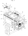
- Figure 1 is a perspective view of a wall-mounted type microwave oven, according to an embodiment of the present invention;
- Figure 2 is an enlarged perspective view of circular portion II of Figure 1;
- Figure 3 is a cross-sectional view taken along line III-III of Figure 2; and
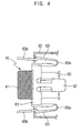
- Figure 4 is a cross-sectional view taken along line IV-IV of Figure 2.
-
- As shown in Figure 1, a wall-mounted type microwave oven according to an embodiment of the present invention is installed on a lower surface of a ceiling or a kitchen cabinet, which is positioned over a gas oven range (not shown). The wall-mounted type microwave oven is provided at an upper surface thereof with an outer duct (not shown), which is connected to the wall-mounted type microwave oven through the ceiling or the kitchen cabinet, so as to guide exhaust gas and food odors generated from the gas oven range positioned therebelow, to an outside.
- The wall-mounted type microwave oven includes an
outer cabinet 10 defining an outer appearance of the wall-mounted type microwave oven, and aninner cabinet 20 disposed in theouter cabinet 10 with a predetermined spacing therebetween, so as to allow air to flow in the predetermined spacing. - The
inner cabinet 20 is provided with acooking chamber 21 therein to cook foods in thecooking chamber 21, and anelectric component compartment 22 to receive various electric components, thecooking chamber 21 andelectric component compartment 22 being isolated from each other by apartition plate 23 disposed therebetween. Thecooking chamber 21 is opened and closed by adoor 24 hingedly coupled to a front surface of thecooking chamber 21. Theelectric component compartment 22 is provided at a front surface thereof with acontrol panel 25 to control various operations of the wall-mounted type microwave oven, and thecontrol panel 25 is positioned adjacent to thedoor 24. - The
electric component compartment 22 is provided therein with electric components, such as amagnetron 22a to generate high-frequency electromagnetic waves into thecooking chamber 21, and ahigh voltage transformer 22b to apply a high voltage to themagnetron 22a. Theelectric component compartment 22 is further provided therein with acooling fan 22c to cool the electric component compartment and to ventilate thecooking chamber 21, and afirst air inlet 26 provided on thecontrol panel 25 to allow indoor air to be introduced into theelectric component compartment 22. Further, afirst exhaust outlet 27 is provided on thedoor 24 to exhaust air discharged from thecooking chamber 21 to a room. - The
partition plate 23 is formed withfirst vent holes 23a to allow the air in theelectric component compartment 22 to be introduced into thecooking chamber 21. Atop panel 21b of thecooking chamber 21 is formed withsecond vent holes 21a to allow the air in the cooking chamber to be discharged through thetop panel 21b. Aguide duct 30 is provided over thesecond vent holes 21a to allow the air discharged through thesecond vent holes 21a to be guided to thefirst exhaust outlet 27. - The
guide duct 30 includes afirst guide part 31 having an area corresponding to an area on which thesecond vent holes 21a are formed in thetop panel 21b, to cover thesecond vent holes 21a, and asecond guide part 32 extending from thefirst guide part 31 and having a opening corresponding to thefirst exhaust outlet 27 to cover thefirst exhaust outlet 27. - Thus, when the
cooling fan 22c is operated, the air in the room is introduced into theelectric component compartment 22 through thefirst air inlet 26 so as to cool the electric components installed in theelectric component compartment 22. Further, the air in theelectric component compartment 22 is introduced into thecooking chamber 21 through thefirst vent holes 23a to ventilate thecooking chamber 21, and discharged to the room through thesecond vent holes 21a, theguide duct 30 and thefirst exhaust outlet 27. - Furthermore, the wall-mounted type microwave oven includes a structure to exhaust gas generated from the gas oven range positioned therebelow. That is, a bottom panel of the
outer cabinet 10, defining a lower surface of the wall-mounted type microwave oven, is provided at first and second sides with asecond air inlet 11, so as to allow the gas and the food odors generated from the gas oven range, to be introduced into theouter cabinet 10, and a top panel of theouter cabinet 10, defining an upper surface of the wall-mounted type microwave oven, is provided withsecond exhaust outlets 12, so as to allow the gas and odors introduced into theouter cabinet 10 to be exhausted to the outside. - An
inner duct 13 defined between theouter cabinet 10 and theinner cabinet 20 extends from under theinner cabinet 20 to thesecond exhaust outlets 12 through a rear surface of theinner cabinet 20, so as to guide the air introduced through thesecond air inlet 11 to thesecond exhaust outlets 12. Theouter cabinet 10 is provided at a rear and upper portion thereof with afan motor 14 to generate a rotating force, and a pair ofexhaust fans 15 are joined to first and second driving shafts of thefan motor 14 to generate a suction force. - Contaminated air, generated by the gas oven range, is introduced into the
outer cabinet 10 through thefirst air inlet 11 by the suction force provided by thefan motor 14 and theexhaust fans 15, and is guided to the outer duct (not shown) through theinner duct 13 and thesecond exhaust outlets 12 to allow the contaminated air to be exhausted to the outside. - The wall-mounted type microwave oven includes various kinds of sensors disposed in the flow path so as to check a temperature and an amount of humidity of air flowing in the flow path.
- A gas sensor may be installed in the
guide duct 30 to check the amount of humidity in the air and an amount of gas contained in the air flowing in theguide duct 30. - As shown in Figure 2, the
gas sensor 40 is installed in theguide duct 30. Theguide duct 30 is formed with acircular fitting hole 33, which is adapted to receive thegas sensor 40. Thegas sensor 40 is coupled to aterminal unit 50, so as to transmit electric power to thegas sensor 40 and to send signals generated from thegas sensor 40 to thecontrol panel 25. Thegas sensor 40 and theterminal unit 50 are fitted into asensor holder 60 to maintain thegas sensor 40 and theterminal unit 50 in a connected state and to allow thegas sensor 40 to be detachably installed to theguide duct 30. - The
gas sensor 40 includes acylindrical detector portion 41 to sense the gas, and aflange portion 42 having a diameter larger than that of thecylindrical detector portion 41 and provided at a side of thecylindrical detector portion 41 to enable thegas sensor 40 to be fitted into thesensor holder 60. Thegas sensor 40 further includes a plurality of connectingpins 43, provided at theflange portion 42, to allow thegas sensor 40 to be connected to theterminal unit 50. - The
terminal unit 50 is provided to transmit the electric power and electrical signals to thegas sensor 40, and includes a plurality of connectingterminals 51 into which the plurality of connectingpins 43 of thegas sensor 40 are fitted, thereby allowing thegas sensor 40 to be electrically connected to theterminal unit 50. - The
sensor holder 60 comprises aring portion 61 having a predetermined diameter to allow thecylindrical detector portion 41 to pass therethrough and to cause theflange portion 42 to be caught thereby, at least two firstelastic clips 62 extending from thering portion 61 to cause thegas sensor 40 and theterminal unit 50, which are connected to each other, to be held in thering portion 61, and at least two secondelastic clips 63 extending from thering portion 61 to cause thesensor holder 60 to be detachably fitted into thecircular fitting hole 33. - As shown in Figure 3, a pair of the first
elastic clips 62 symmetrically extends from thering portion 61 toward theterminal unit 50. The pair of firstelastic clips 62 is provided at inner facing surfaces thereof with bulginghooks 62a, respectively, to be engaged to theterminal unit 50. Theterminal unit 50 includes twoelastic pieces 52, which are adapted to be engaged to thebulging hooks 62a of the firstelastic clips 62. Thus, when thegas sensor 40 and theterminal unit 60, which are connected to each other, are inserted into thesensor holder 60, theflange portion 42 of thegas sensor 40 is fitted into thering portion 61 of thesensor holder 60, and theelastic pieces 52 of theterminal unit 50 are engaged to thebulging hooks 62a of thesensor holder 60. Therefore, thegas sensor 40 and theterminal unit 50 are detachably fitted into thesensor holder 60. - As shown in Figure 4, each of the second
elastic clips 63 includes a "U"-shapedelastic portion 63a extending from thering portion 61, and anextension portion 63b extending from a free end of the "U"-shapedelastic portion 63a with a stepped portion therebetween, so as to cause the stepped portion of each of the secondelastic clip 63 to be caught by thecircular fitting hole 33. For an engagement between each of the secondelastic clips 63 and the circularfitting hole 33, theguide duct 30 is formed with twocut portions 33a at diametrically opposite points on an edge of the circularfitting hole 33. Accordingly, when thesensor holder 60 is inserted into the circularfitting hole 33, the stepped portions of each of the secondelastic clips 63 are caught by thecut portions 33a of the circularfitting hole 33, thereby causing thesensor holder 60 to be detachably fitted into the circularfitting hole 33. - Although the
sensor holder 60 is used to hold thegas sensor 40, thesensor holder 60 may be used to hold other types of sensors than that of thegas sensor 40. - Furthermore, although the circular
fitting hole 33 is described as being formed at theguide duct 30, thefitting hole 33 may be formed at any portion of a wall defining the flow path. - An operation of fitting and detaching the
gas sensor 40 of the wall-mounted type microwave oven, according to the embodiment of the present invention will now be described with reference to the drawings. - First, an operation of installing the
gas sensor 40 to theguide duct 30 is described. Thegas sensor 40 is coupled to theterminal unit 50, and the coupledgas sensor 40 andterminal unit 50 are inserted into thesensor holder 60. - As the
gas sensor 40 and theterminal unit 50 are inserted into thesensor holder 60, theflange portion 42 of thegas sensor 40 is fitted into thering portion 61, and theelastic pieces 52 of theterminal unit 50 are engaged with the bulginghooks 62a of the first elastic clips 62. Therefore, thegas sensor 40 and theterminal unit 50 are firmly held in thesensor holder 60. - Further, the
sensor holder 60, in which thegas sensor 40 and theterminal unit 50 are held, is inserted into the circularfitting hole 33 of theguide duct 30. At this point, the stepped portions of the secondelastic clips 63 are caught by thecut portions 33a of the circularfitting hole 33, thereby causing thegas sensor 40 to be fitted in the circularfitting hole 33. - When a replacement of a
defective gas sensor 40 with a new one is needed, the secondelastic clips 63 of thesensor holder 60, which are fitted to theguide duct 30, are pushed toward each other by a user to disengage the stepped portions of the second elastic clips 63. Thereafter, thesensor holder 60 is forwardly pulled from theguide duct 30. - Subsequently, the pair of first
elastic clips 62 is outwardly deformed to allow thegas sensor 40 and theterminal unit 50 to be separated from thesensor holder 60. Thegas sensor 40 is detached from theterminal unit 50, and replaced with a new gas sensor. Accordingly, a major portion of an operation of installing and detaching thegas sensor 40 is performed outside theguide duct 30. - As is apparent from the above description, a wall-mounted type microwave oven with a sensor holder to hold a gas sensor and a terminal unit therein, the sensor holder being detachably fitted to a guide duct. Accordingly, only an operation of separating the sensor holder from the guide duct is performed in the guide duct, and an operation of pulling the gas sensor and the terminal unit out of the sensor holder and detaching the gas sensor from the terminal unit is performed outside the guide duct. Therefore, the wall-mounted type microwave oven enables the gas sensor to be easily fitted to and detached from the wall-mounted type microwave oven.
- Although a few preferred embodiments have been shown and described, it will be appreciated by those skilled in the art that various changes and modifications might be made without departing from the scope of the invention, as defined in the appended claims.
- Attention is directed to all papers and documents which are filed concurrently with or previous to this specification in connection with this application and which are open to public inspection with this specification, and the contents of all such papers and documents are incorporated herein by reference.
- All of the features disclosed in this specification (including any accompanying claims, abstract and drawings), and/or all of the steps of any method or process so disclosed, may be combined in any combination, except combinations where at least some of such features and/or steps are mutually exclusive.
- Each feature disclosed in this specification (including any accompanying claims, abstract and drawings) may be replaced by alternative features serving the same, equivalent or similar purpose, unless expressly stated otherwise. Thus, unless expressly stated otherwise, each feature disclosed is one example only of a generic series of equivalent or similar features.
- The invention is not restricted to the details of the foregoing embodiment(s). The invention extends to any novel one, or any novel combination, of the features disclosed in this specification (including any accompanying claims, abstract and drawings), or to any novel one, or any novel combination, of the steps of any method or process so disclosed.
Claims (34)
- A wall-mounted type microwave oven, comprising:an outer cabinet (10) defining an outer appearance of the wall-mounted-type microwave oven;an inner cabinet (20) disposed in the outer cabinet (10) to define a flow path (30) therebetween and including a cooking chamber (21) and an electric component compartment (22) therein;a sensor (40) disposed in the flow path (30) defined between the outer cabinet (10) and the inner cabinet (20) to check a condition of air flowing in the flow path (30);a terminal unit (50) connected to the sensor (40) to transmit electric power and control signals to the sensor (40);a fitting hole (33) provided at a wall defining the flow path (30) to hold the sensor (40) and the terminal unit (50) ; anda sensor holder (60) to hold the sensor (40) and the terminal unit (50) coupled to each other therein, and to be detachably fitted in the fitting hole (33) together with the sensor (40) and the terminal unit (50).
- The wall-mounted type microwave oven as set forth in claim 1, wherein:the sensor (40) comprises:a detector portion (41) to check the condition of the air flowing in the flow path (30); anda flange portion (42) radially enlarged from the detector portion (41) to engage with the sensor holder (60); andthe sensor holder (60) comprises:a ring portion (61) sized to allow the detector portion (41) to pass therethrough and to catch the flange portion (42) of the sensor (40) thereby; andat least two first elastic clips (62) extending from the ring portion (61) to elastically support the terminal unit (50) connected to the sensor (40).
- The wall-mounted type microwave oven as set forth in claim 2, wherein each of the first elastic clips comprises:a plurality of hooks (62a) provided at inner facing surfaces thereof, which protrude toward the terminal unit (50) to prevent the terminal unit (50) from separating from the ring portion (61) of the sensor holder (60).
- The wall-mounted type microwave oven as set forth in claim 3, wherein the terminal unit (50) comprises:a plurality of elastic pieces (52) provided at positions corresponding to the plurality of hooks (62a) of the first elastic clips to respectively engage with respective ones of the plurality of the hooks.
- The wall-mounted type microwave oven as set forth in claim 2, 3 or 4 wherein the sensor holder (60) further comprises:at least two second elastic clips (63) extending from the ring portion (61) of the sensor holder (60) to enable the sensor holder (60) to detachably fit in the fitting hole (33).
- The wall-mounted type microwave oven as set forth in claim 5, wherein:the wall defining the flow path (30) and having the fitting hole (33) is formed with cut portions (33a) at positions adjacent to the fitting hole (33) and corresponding to the at least two second elastic clips (63), so as to cause the at least two second elastic clips (63) to be caught by the cut portions (33a), respectively, each of the second elastic clips comprises:a "U"-shaped elastic portion (63a) extending from the ring portion (61) of the sensor holder (60);an extension portion (63b) extending from a free end of the "U"-shaped elastic portion (63a); anda stepped portion between the "U"-shaped elastic portion (63a) and the extension portion (63b).
- The wall-mounted type microwave oven as set forth in any preceding claim, wherein the sensor (40) comprises:a gas sensor (40) to check an amount of humidity in the air flowing in the flow path (30) and an amount of gas contained in the air flowing in the flow path (30).
- The wall-mounted type microwave oven as set forth in any preceding claim, further comprising;
a guide duct (30) disposed at an upper portion of the cooking chamber (21) to guide air discharged from the cooking chamber (21) to a front surface of the outer cabinet (10), wherein the fitting hole (33) is provided at the guide duct (30). - A wall-mounted type microwave oven having an exhaust path (30) to exhaust air therebelow, and a fitting hole (33) formed at a wall defining the exhaust path (30), comprising:a sensor (40) disposed in the exhaust path (30) to check a condition of air flowing in the exhaust path (30);a terminal unit (50) connected to the sensor (40) to provide electric power and control signals to the sensor (40); anda sensor holder (60) to hold the sensor (40) and the terminal unit (50) coupled to each other therein, and to detachably fit in the fitting hole (33) together with the sensor (40) and the terminal unit (50).
- The wall-mounted type microwave oven as set forth in claim 9, wherein:the sensor (40) comprises:a detector portion (41) to check the condition of the air flowing in the exhaust path (30), and a flange portion (42) larger in a radius thereof than that of the detector portion (41) to detachably engage with the sensor holder (60); andthe sensor holder (60) comprises:a ring portion (61) to allow the detector portion (41) to pass therethrough and to detachably engage with the flange portion (42) of the sensor (40), and two or more first clips extending from the ring portion (61) to elastically support the terminal unit (50) connected to the sensor (40).
- The wall-mounted type microwave oven as set forth in claim 10, wherein each of the first clips comprises:a plurality of hooks (62a) provided at inner facing surfaces thereof and protruding toward the terminal unit (50) to prevent the terminal unit (50) from separating from the ring portion (61) of the sensor holder (60).
- The wall-mounted type microwave oven as set forth in claim 11, wherein the terminal unit (50) comprises:a plurality of elastic pieces (52) provided at positions corresponding to the plurality of hooks (62a) of the first clips to respectively engage with the plurality of hooks (62a).
- The wall-mounted type microwave oven as set forth in claim 11 or 12, wherein the sensor holder (60) further comprises:two or more second clips extending from the ring portion (61) of the sensor holder (60) to detachably fit the sensor holder (60) into the fitting hole (33).
- The wall-mounted type microwave oven as set forth in claim 13, further comprising:a wall defining the exhaust path (30) formed with cut portions (33a) at positions adjacent to the fitting hole (33) and corresponding to the two or more second clips, so as engage with respective ones of the two or more second clips by the cut portions (33a).
- The wall-mounted type microwave oven as set forth in claim 13 or 14, wherein each of the second clips comprises:a "U"-shaped portion extending from the ring portion (61) of the sensor holder (60);an extension portion (63b) extending from a free end of the "U"-shaped portion; anda stepped portion between the "U"-shaped portion and the extension portion (63b).
- The wall-mounted type microwave oven as set forth in any of claims 9 to 15, wherein the sensor (40) comprises:a gas sensor (40) to check an amount of humidity in the air flowing in the exhaust path (30) and an amount of gas contained in the air flowing in the exhaust path (30).
- The wall-mounted type microwave oven as set forth in any of claims 9 to 16, further comprising;
a cooking chamber (21); and
a guide duct (30) disposed at an upper front surface of the wall-mounted type microwave oven to guide air discharged from the cooking chamber (21) such that the sensor (40) is provided in the guide duct (30). - The wall-mounted type microwave oven as set forth in claim 17, further comprising;
an inner cabinet (20) defining the cooking chamber (21) therein; and
an outer cabinet (10) defining an appearance of an exterior of the wall-mounted type microwave, wherein the exhaust path (30) is defined between the inner and outer cabinets. - The wall-mounted type microwave oven as set forth in any of claims 9 to 18, wherein the sensor (40) is provided to check one or more of a temperature, a humidity and a gas concentration in the exhaust path (30).
- The wall-mounted type microwave oven as set forth in any of claims 9 to 19, wherein:the flange portion (42) of the sensor (40) comprises:a plurality of connecting pins to detachably connect the sensor (40) to the terminal unit (50); andthe terminal unit (50) comprises:a plurality of connecting terminals into which respective ones of the plurality of connecting pins of the sensor (40) are fittable to electrically connect the sensor (40) to the terminal unit (50).
- The wall-mounted type microwave oven as set forth in any of claims 9 to 20, wherein:the sensor (40) is detachable from the terminal unit (50) outside of the wall mounted-type microwave oven.
- A sensor unit to fit to a wall of an exhaust path (30) of a wall-mounted type microwave oven, comprising:a sensor (40) disposed in the exhaust path (30) to check a condition of air flowing in the exhaust path (30);a terminal unit (50) connected to the sensor (40) to provide electric power and control signals to the sensor (40) ; anda sensor holder (60) to hold the sensor (40) and the terminal unit (50) coupled to each other therein, and to detachably attach to the wall of the exhaust path (30) together with the sensor (40) and the terminal unit (50).
- The sensor unit as set forth in claim 22, wherein:the sensor (40) comprises:a detector portion (41) to check the condition of the air flowing in the exhaust path (30), and a flange portion (42) larger in a radius thereof than that of the detector portion (41) to detachably engage with the sensor holder (60); andthe sensor holder (60) comprises:a ring portion (61) to allow the detector portion (41) to pass therethrough and to detachably engage with the flange portion (42) of the sensor (40); andtwo or more first clips extending from the ring portion (61) to elastically support the terminal unit (50) connected to the sensor (40).
- The sensor unit as set forth in claim 23, wherein each of the first clips comprises:a plurality of hooks (62a) provided at inner facing surfaces thereof and protruding toward the terminal unit (50) to prevent the terminal unit (50) from separating from the ring portion (61) of the sensor holder (60).
- The sensor unit as set forth in claim 24, wherein the terminal unit (50) comprises:a plurality of elastic pieces (52) provided at positions corresponding to the plurality of hooks (62a) of the first clips to respectively engage with the plurality of hooks (62a).
- The sensor unit as set forth in claim 24 or 25, wherein the sensor holder (60) further comprises:two or more second clips extending from the ring portion (61) of the sensor holder (60) to detachably fit the sensor holder (60) into the fitting hole (33).
- The sensor unit as set forth in claim 26, further comprising:a wall defining the exhaust path (30) formed with cut portions (33a) at positions adjacent to the fitting hole (33) and corresponding to the two or more second clips, so as engage with respective ones of the two or more second clips by the cut portions (33a).
- The sensor unit as set forth in claim 26 or 27, wherein each of the second clips comprises:a "U"-shaped portion extending from the ring portion (61) of the sensor holder (60);an extension portion (63b) extending from a free end of the "U"-shaped portion; anda stepped portion between the "U"-shaped portion and the extension portion (63b).
- The sensor unit as set forth in any of claims 22 to 28, wherein the sensor (40) comprises:a sensor (40) to check an amount of humidity in the air flowing in the exhaust path (30) and an amount of gas contained in the air flowing in the exhaust path (30).
- The sensor unit as set forth in any of claims 22 to 29, wherein:the flange portion (42) of the sensor (40) comprises:a plurality of connecting pins to detachably connect the sensor (40) to the terminal unit (50); andthe terminal unit (50) comprises:a plurality of connecting terminals into which respective ones of the plurality of connecting pins of the sensor (40) are fittable to electrically connect the sensor (40) to the terminal unit (50).
- The sensor unit as set forth in any of claims 22 to 30, wherein the sensor (40) is provided to check one or more of a temperature, a humidity and a gas concentration in the exhaust path (30).
- A wall-mounted type microwave oven, comprising:a sensor unit (40) as set forth in any of claims 22 to 31;a cooking chamber (21); anda guide duct (30) disposed at an upper front surface of the wall-mounted type microwave oven to guide air discharged from the cooking chamber (21) such that the sensor (40) is provided in the guide duct (30).
- The wall-mounted type microwave oven as set forth in claim 32, further comprising;
an inner cabinet (20) defining the cooking chamber (21) therein; and
an outer cabinet (10) defining an appearance of an exterior of the wall-mounted type microwave, wherein the exhaust path (30) is defined between the inner and outer cabinets. - A microwave oven having an exhaust path (30) to exhaust air, and a fitting hole (33) formed at a wall defining the exhaust path (30), comprising:a sensor (40) disposed in the exhaust path (30) to check a condition of air flowing in the exhaust path (30);a terminal unit (50) connected to the sensor (40) to provide electric power and control signals to the sensor (40); anda sensor holder (60) to hold the sensor (40) and the terminal unit (50) coupled to each other therein, and to detachably fit in the fitting hole (33) together with the sensor (40) and the terminal unit (50) such that a detachment of the sensor (40) from the terminal unit (50) occurs outside of the microwave oven.
Applications Claiming Priority (2)
| Application Number | Priority Date | Filing Date | Title |
|---|---|---|---|
| KR2003001436 | 2003-01-09 | ||
| KR10-2003-0001436A KR100499023B1 (en) | 2003-01-09 | 2003-01-09 | Wall-mounted type microwave oven |
Publications (2)
| Publication Number | Publication Date |
|---|---|
| EP1437925A1 true EP1437925A1 (en) | 2004-07-14 |
| EP1437925B1 EP1437925B1 (en) | 2006-06-21 |
Family
ID=36686667
Family Applications (1)
| Application Number | Title | Priority Date | Filing Date |
|---|---|---|---|
| EP03257320A Expired - Lifetime EP1437925B1 (en) | 2003-01-09 | 2003-11-19 | Wall-mounted type microwave oven |
Country Status (6)
| Country | Link |
|---|---|
| US (1) | US6852963B2 (en) |
| EP (1) | EP1437925B1 (en) |
| JP (1) | JP2004219047A (en) |
| KR (1) | KR100499023B1 (en) |
| CN (1) | CN1245590C (en) |
| DE (1) | DE60306322T2 (en) |
Cited By (2)
| Publication number | Priority date | Publication date | Assignee | Title |
|---|---|---|---|---|
| WO2018038882A1 (en) | 2016-08-26 | 2018-03-01 | Rosemount Inc. | Tool-less replaceable gas sensor module |
| WO2020099608A1 (en) * | 2018-11-15 | 2020-05-22 | Seb S.A. | Removable device for analysing the odours produced in an electrical household appliance, method for calibrating the removable device, and cooking method for an electrical household appliance equipped with the removable device |
Families Citing this family (13)
| Publication number | Priority date | Publication date | Assignee | Title |
|---|---|---|---|---|
| KR20060122128A (en) * | 2005-05-25 | 2006-11-30 | 삼성전자주식회사 | Cooling time control device of microwave oven and its method |
| DE102006005321B3 (en) * | 2006-02-06 | 2007-09-20 | Bleckmann Gmbh & Co. Kg | Schnappflansch |
| KR101138886B1 (en) * | 2007-02-28 | 2012-05-14 | 삼성전자주식회사 | Dish washer |
| WO2011028729A1 (en) | 2009-09-01 | 2011-03-10 | Manitowoc Foodservice Companies, Llc | Method and apparatus for an air inlet in a cooking device |
| JP5300930B2 (en) * | 2011-07-25 | 2013-09-25 | 三菱電機株式会社 | Cooker |
| US9052260B2 (en) * | 2012-06-18 | 2015-06-09 | Alan B. Powell | System, components, and methods for detecting moisture |
| KR101645822B1 (en) * | 2014-12-05 | 2016-08-04 | 동부대우전자 주식회사 | Over the range and method of use thereof |
| KR101686304B1 (en) * | 2014-12-05 | 2016-12-13 | 동부대우전자 주식회사 | Over the range and method of use thereof |
| EP3125645A1 (en) | 2015-07-31 | 2017-02-01 | Bleckmann GmbH & Co. KG | Flange assembly for securing a heating device to a fluid container |
| US11540363B2 (en) * | 2019-11-11 | 2022-12-27 | Haier Us Appliance Solutions, Inc. | Microwave appliance having a secondary cooking chamber |
| KR102276298B1 (en) * | 2020-07-10 | 2021-07-15 | 주식회사 에라토 | range hood with gas and dust detection |
| US12495471B2 (en) * | 2022-05-26 | 2025-12-09 | Honeywell Federal Manufacturing & Technologies, Llc | Butanedione sensor for microwave control |
| US20240302221A1 (en) * | 2023-03-10 | 2024-09-12 | David Kogut | Oven Device with Internal Meat Thermometer Device |
Citations (5)
| Publication number | Priority date | Publication date | Assignee | Title |
|---|---|---|---|---|
| US4295028A (en) * | 1979-02-23 | 1981-10-13 | Sharp Kabushiki Kaisha | Combination of gas sensor controlled cooking utensil and gas leak alarm |
| US4319110A (en) * | 1979-05-22 | 1982-03-09 | Sharp Kabushiki Kaisha | Microwave oven employing a gas sensor |
| US4463238A (en) * | 1979-03-06 | 1984-07-31 | Sharp Kabushiki Kaisha | Combined microwave and electric heating oven selectively controlled by gas sensor output and thermistor output |
| US4587393A (en) * | 1984-01-05 | 1986-05-06 | Matsushita Electric Industrial Co., Ltd. | Heating apparatus having a sensor for terminating operation |
| US6335518B1 (en) * | 2000-10-26 | 2002-01-01 | Samsung Electronics Co., Ltd. | Microwave oven with temperature sensor assembly |
Family Cites Families (7)
| Publication number | Priority date | Publication date | Assignee | Title |
|---|---|---|---|---|
| JPS611925A (en) * | 1984-06-13 | 1986-01-07 | Matsushita Electric Ind Co Ltd | Cooking device |
| IT1202546B (en) * | 1987-02-13 | 1989-02-09 | Eurodomestici Ind Riunite | IMPROVEMENTS IN MICROWAVE OVENS SUITABLE TO ALLOW THE AUTOMATIC HEATING OF FOOD |
| KR910007503Y1 (en) * | 1989-12-31 | 1991-09-27 | 대우전자부품 주식회사 | Humidity sensor for electronic range |
| KR930003478Y1 (en) * | 1991-06-28 | 1993-06-14 | 대우전자 주식회사 | Humidity sensor mounting structure of microwave oven |
| JPH0510912A (en) | 1991-07-03 | 1993-01-19 | Sharp Corp | Humidity sensor mounting device for high-frequency heating device |
| KR970044180U (en) * | 1995-12-29 | 1997-07-31 | Thermostat Mounting Structure | |
| KR19990017324U (en) * | 1997-10-31 | 1999-05-25 | 전주범 | Thermostat Bracket of High Voltage Transformer for Microwave Oven |
-
2003
- 2003-01-09 KR KR10-2003-0001436A patent/KR100499023B1/en not_active Expired - Lifetime
- 2003-07-02 US US10/610,528 patent/US6852963B2/en not_active Expired - Lifetime
- 2003-10-24 JP JP2003364998A patent/JP2004219047A/en active Pending
- 2003-11-06 CN CNB2003101036303A patent/CN1245590C/en not_active Expired - Fee Related
- 2003-11-19 DE DE60306322T patent/DE60306322T2/en not_active Expired - Lifetime
- 2003-11-19 EP EP03257320A patent/EP1437925B1/en not_active Expired - Lifetime
Patent Citations (5)
| Publication number | Priority date | Publication date | Assignee | Title |
|---|---|---|---|---|
| US4295028A (en) * | 1979-02-23 | 1981-10-13 | Sharp Kabushiki Kaisha | Combination of gas sensor controlled cooking utensil and gas leak alarm |
| US4463238A (en) * | 1979-03-06 | 1984-07-31 | Sharp Kabushiki Kaisha | Combined microwave and electric heating oven selectively controlled by gas sensor output and thermistor output |
| US4319110A (en) * | 1979-05-22 | 1982-03-09 | Sharp Kabushiki Kaisha | Microwave oven employing a gas sensor |
| US4587393A (en) * | 1984-01-05 | 1986-05-06 | Matsushita Electric Industrial Co., Ltd. | Heating apparatus having a sensor for terminating operation |
| US6335518B1 (en) * | 2000-10-26 | 2002-01-01 | Samsung Electronics Co., Ltd. | Microwave oven with temperature sensor assembly |
Cited By (4)
| Publication number | Priority date | Publication date | Assignee | Title |
|---|---|---|---|---|
| WO2018038882A1 (en) | 2016-08-26 | 2018-03-01 | Rosemount Inc. | Tool-less replaceable gas sensor module |
| EP3504536B1 (en) * | 2016-08-26 | 2023-03-15 | Rosemount Inc. | Tool-less replaceable gas sensor module |
| WO2020099608A1 (en) * | 2018-11-15 | 2020-05-22 | Seb S.A. | Removable device for analysing the odours produced in an electrical household appliance, method for calibrating the removable device, and cooking method for an electrical household appliance equipped with the removable device |
| FR3088726A1 (en) * | 2018-11-15 | 2020-05-22 | Seb S.A. | REMOVABLE DEVICE FOR ANALYZING ODORS GENERATED IN AN OVEN, METHOD FOR CALIBRATING THE REMOVABLE DEVICE, AND COOKING METHOD FOR AN OVEN EQUIPPED WITH THE REMOVABLE DEVICE. |
Also Published As
| Publication number | Publication date |
|---|---|
| CN1517599A (en) | 2004-08-04 |
| KR100499023B1 (en) | 2005-07-01 |
| US6852963B2 (en) | 2005-02-08 |
| US20040134901A1 (en) | 2004-07-15 |
| EP1437925B1 (en) | 2006-06-21 |
| KR20040064137A (en) | 2004-07-16 |
| DE60306322D1 (en) | 2006-08-03 |
| JP2004219047A (en) | 2004-08-05 |
| CN1245590C (en) | 2006-03-15 |
| DE60306322T2 (en) | 2007-06-06 |
Similar Documents
| Publication | Publication Date | Title |
|---|---|---|
| EP1437925B1 (en) | Wall-mounted type microwave oven | |
| EP1439740B1 (en) | Wall-mounted type microwave oven | |
| EP0965797B1 (en) | Combined microwave oven and extractor | |
| EP0866643B1 (en) | Microwave oven | |
| US12432825B2 (en) | Cooking apparatus | |
| CN109690193B (en) | Cooking utensil | |
| EP1542510B1 (en) | Wall mounted type microwave oven | |
| EP1437922B1 (en) | Cooking appliance and a motor mounting unit therefore | |
| KR20040052325A (en) | Wall mounting type microwave oven | |
| US6818874B2 (en) | Wall-mounted type microwave oven | |
| US6717122B2 (en) | Wall-mounted microwave oven and structure for removing magnetron | |
| EP1437924B1 (en) | Wall-mounted type microwave oven | |
| KR101625679B1 (en) | Microwave oven having hood | |
| US20240060652A1 (en) | Cooking equipment | |
| CN215838479U (en) | Cooking appliance with circulating air duct | |
| KR101652999B1 (en) | Microwave oven having hood | |
| EP0584933A1 (en) | Heating apparatus enclosed in a cabinet during its use | |
| KR100551489B1 (en) | Wall-mounted Microwave | |
| KR200143553Y1 (en) | Fixing device for mini manual for microwave oven | |
| KR19990041012U (en) | microwave | |
| KR100265644B1 (en) | Wall tapestry type microwave oven | |
| KR19980036834U (en) | Over the microwave thermostat installation structure | |
| KR20050036431A (en) | A lower passage of cavity for mocrowave oven | |
| KR19980067681A (en) | Fixture for duct for microwave | |
| KR19980050395U (en) | High installation lamp installation structure of over the microwave |
Legal Events
| Date | Code | Title | Description |
|---|---|---|---|
| PUAI | Public reference made under article 153(3) epc to a published international application that has entered the european phase |
Free format text: ORIGINAL CODE: 0009012 |
|
| 17P | Request for examination filed |
Effective date: 20031210 |
|
| AK | Designated contracting states |
Kind code of ref document: A1 Designated state(s): AT BE BG CH CY CZ DE DK EE ES FI FR GB GR HU IE IT LI LU MC NL PT RO SE SI SK TR |
|
| AX | Request for extension of the european patent |
Extension state: AL LT LV MK |
|
| AKX | Designation fees paid |
Designated state(s): DE FR GB |
|
| GRAP | Despatch of communication of intention to grant a patent |
Free format text: ORIGINAL CODE: EPIDOSNIGR1 |
|
| RIN1 | Information on inventor provided before grant (corrected) |
Inventor name: JEONG, SANG-JIN, 103-902 JOWONJOOKONGNEWTOWN |
|
| GRAS | Grant fee paid |
Free format text: ORIGINAL CODE: EPIDOSNIGR3 |
|
| GRAA | (expected) grant |
Free format text: ORIGINAL CODE: 0009210 |
|
| AK | Designated contracting states |
Kind code of ref document: B1 Designated state(s): DE FR GB |
|
| REG | Reference to a national code |
Ref country code: GB Ref legal event code: FG4D |
|
| REF | Corresponds to: |
Ref document number: 60306322 Country of ref document: DE Date of ref document: 20060803 Kind code of ref document: P |
|
| ET | Fr: translation filed | ||
| PLBE | No opposition filed within time limit |
Free format text: ORIGINAL CODE: 0009261 |
|
| STAA | Information on the status of an ep patent application or granted ep patent |
Free format text: STATUS: NO OPPOSITION FILED WITHIN TIME LIMIT |
|
| 26N | No opposition filed |
Effective date: 20070322 |
|
| REG | Reference to a national code |
Ref country code: FR Ref legal event code: PLFP Year of fee payment: 14 |
|
| REG | Reference to a national code |
Ref country code: FR Ref legal event code: PLFP Year of fee payment: 15 |
|
| REG | Reference to a national code |
Ref country code: FR Ref legal event code: PLFP Year of fee payment: 16 |
|
| PGFP | Annual fee paid to national office [announced via postgrant information from national office to epo] |
Ref country code: DE Payment date: 20181022 Year of fee payment: 16 |
|
| PGFP | Annual fee paid to national office [announced via postgrant information from national office to epo] |
Ref country code: GB Payment date: 20181023 Year of fee payment: 16 Ref country code: FR Payment date: 20181029 Year of fee payment: 16 |
|
| REG | Reference to a national code |
Ref country code: DE Ref legal event code: R082 Ref document number: 60306322 Country of ref document: DE Representative=s name: WUNDERLICH & HEIM PATENTANWAELTE PARTNERSCHAFT, DE |
|
| REG | Reference to a national code |
Ref country code: DE Ref legal event code: R119 Ref document number: 60306322 Country of ref document: DE |
|
| GBPC | Gb: european patent ceased through non-payment of renewal fee |
Effective date: 20191119 |
|
| PG25 | Lapsed in a contracting state [announced via postgrant information from national office to epo] |
Ref country code: DE Free format text: LAPSE BECAUSE OF NON-PAYMENT OF DUE FEES Effective date: 20200603 Ref country code: GB Free format text: LAPSE BECAUSE OF NON-PAYMENT OF DUE FEES Effective date: 20191119 Ref country code: FR Free format text: LAPSE BECAUSE OF NON-PAYMENT OF DUE FEES Effective date: 20191130 |