EP1437924A1 - Wall-mounted type microwave oven - Google Patents
Wall-mounted type microwave oven Download PDFInfo
- Publication number
- EP1437924A1 EP1437924A1 EP20030257319 EP03257319A EP1437924A1 EP 1437924 A1 EP1437924 A1 EP 1437924A1 EP 20030257319 EP20030257319 EP 20030257319 EP 03257319 A EP03257319 A EP 03257319A EP 1437924 A1 EP1437924 A1 EP 1437924A1
- Authority
- EP
- European Patent Office
- Prior art keywords
- wall
- microwave oven
- mounted type
- type microwave
- nut
- Prior art date
- Legal status (The legal status is an assumption and is not a legal conclusion. Google has not performed a legal analysis and makes no representation as to the accuracy of the status listed.)
- Granted
Links
Images

Classifications
-
- F—MECHANICAL ENGINEERING; LIGHTING; HEATING; WEAPONS; BLASTING
- F24—HEATING; RANGES; VENTILATING
- F24C—DOMESTIC STOVES OR RANGES ; DETAILS OF DOMESTIC STOVES OR RANGES, OF GENERAL APPLICATION
- F24C15/00—Details
- F24C15/08—Foundations or supports plates; Legs or pillars; Casings; Wheels
-
- H—ELECTRICITY
- H05—ELECTRIC TECHNIQUES NOT OTHERWISE PROVIDED FOR
- H05B—ELECTRIC HEATING; ELECTRIC LIGHT SOURCES NOT OTHERWISE PROVIDED FOR; CIRCUIT ARRANGEMENTS FOR ELECTRIC LIGHT SOURCES, IN GENERAL
- H05B6/00—Heating by electric, magnetic or electromagnetic fields
- H05B6/64—Heating using microwaves
- H05B6/6426—Aspects relating to the exterior of the microwave heating apparatus, e.g. metal casing, power cord
- H05B6/6429—Aspects relating to mounting assemblies of wall-mounted microwave ovens
Definitions
- the present invention relates to a wall-mounted type microwave oven, and more particularly, to a wall-mounted type microwave oven, which is adapted to prevent a deformation and a drooping of an outer cabinet thereof.
- a microwave oven is a cooking appliance which is intended to cook foods by intermolecular frictional heating of the foods, which is generated by repeatedly agitating water molecules of the foods with high-frequency electromagnetic energy.
- a microwave oven which is fixedly installed over a cooking device, such as a gas oven range, to serve as a hood to exhaust contaminated air to an outside, is usually referred as a wall-mounted type microwave oven.
- a conventional wall-mounted type microwave oven is generally installed over the gas oven range in a kitchen, and performs an operation of exhausting, for example, exhaust gas and fumes generated from the gas oven range disposed therebelow, to the outside, as well as a cooking operation as in a conventional wall-mounted type microwave oven.
- the wall-mounted type microwave oven includes an outer cabinet defining an outer appearance of the wall-mounted type microwave oven, and an inner cabinet disposed in the outer cabinet with a predetermined spacing therebetween, so as to enable the predetermined spacing to serve as a duct to guide contaminated air.
- the inner cabinet is provided therein with a cooking chamber to cook foods therein, and an electric component compartment to receive various electric components, the cooking chamber and electric component compartment being isolated from each other.
- the wall-mounted type microwave oven includes an upper panel having an upper surface of the outer cabinet, which is securely attached to a lower surface of an installation base, such as a ceiling of the kitchen or a kitchen cabinet, by fasteners such as bolts and nuts and is thereby suspended.
- an installation base such as a ceiling of the kitchen or a kitchen cabinet
- fasteners such as bolts and nuts and is thereby suspended.
- the nuts are first held by additional nut holders attached to a lower surface of the upper panel, and the bolts are passed through the installation base and the outer cabinet and engaged with the nuts.
- the outer cabinet of the conventional wall-mounted type microwave oven is comprised of thin plate material, the upper panel of the outer cabinet may be deformed or may droop by a weight of the wall-mounted type microwave oven over time.
- Another aim is to provide a wall-mounted type microwave oven, which reduces a number of associated components, thereby decreasing production cost.
- a wall-mounted type microwave oven including an outer cabinet defining an outer appearance of the wall-mounted type microwave oven, an inner cabinet disposed in the outer cabinet with a predetermined spacing therebetween, and having a cooking chamber to cook foods therein and an electric component compartment to receive electric components.
- the cooking chamber and the electric component compartments are isolated from each other.
- a hanger member extends from the inner cabinet to allow the inner cabinet to be secured to an installation base in a kitchen, and a fastening device secures the hanger member to the installation base.
- the fastening device includes a bolt and a nut.
- the bolt passes through the installation base, the outer cabinet and the hanger member.
- the nut is disposed under the hanger member and engages with the bolt.
- the hanger member includes a seat piece on which the nut is seated, and a resilient hook piece to allow the nut to be seated on the seat piece and to prevent the nut from separating from the seat piece.
- the seat piece is downwardly extended from a lower surface of the hanger member and laterally bent to have an "L"-shaped section, so as to allow the nut to be seated on the bent portion, and the resilient hook piece is positioned at an opening side of the seat piece to prevent the nut from separating from the seat piece.
- the nut has a square shape, which is in contact with the seat piece and the resilient hook piece at sides thereof, so as not to allow the nut to rotate when the bolt engages therewith.
- the hanger member extends from a partition plate, which is attached to an upper and front portion of the inner cabinet defining the electric component compartment, to define a flow path to cool the electric component compartment.
- the wall-mounted type microwave oven As shown in Figures 1 and 2, the wall-mounted type microwave oven according to the embodiment of the present invention is installed to a lower surface of an installation base "I" provided at a ceiling or a kitchen cabinet, which is positioned over a gas oven range (not shown).
- the wall-mounted type microwave oven is located at an upper surface thereof with an outer duct D, which is connected to the wall-mounted type microwave oven through the ceiling or the kitchen cabinet, so as to guide exhaust gas and food odors generated from the gas oven range positioned therebelow, to the outside.
- the wall-mounted type microwave oven includes an outer cabinet 10 defining an outer appearance of the wall-mounted type microwave oven, and an inner cabinet 20 disposed in the outer cabinet 10 with a predetermined spacing therebetween, so as to enable the predetermined spacing to serve as an inner duct 30 to guide contaminated air therethrough.
- the inner cabinet 20 includes a cooking chamber 21 to cook foods therein, and an electric component compartment 22 to receive various electric components, the cooking chamber 21 and the electric component compartment 22 being isolated from each other.
- the cooking chamber 21 is opened and closed by a door 23 hingedly coupled to a front surface of the cooking chamber 21.
- the electric component compartment 22 includes at a front surface thereof a control panel 24 to control various operations of the wall-mounted type microwave oven, which is positioned adjacent to the door 23.
- the electric component compartment 22 includes electric components such as a magnetron 22a to generate high-frequency electromagnetic waves into the cooking chamber 21, a high voltage transformer 22b to apply high voltage to the magnetron 22a, and a cooling fan 22c to cool the electric components received in the electric component compartment 22.
- electric components such as a magnetron 22a to generate high-frequency electromagnetic waves into the cooking chamber 21, a high voltage transformer 22b to apply high voltage to the magnetron 22a, and a cooling fan 22c to cool the electric components received in the electric component compartment 22.
- a lower panel, which defines a lower surface of the outer cabinet 10, includes at sides thereof intake ports 11, so as to introduce the contaminated air containing exhaust gas and the food odors generated from the gas oven range positioned therebelow, into the outer cabinet 10.
- An upper panel, which defines an upper surface of the outer cabinet 10, includes an exhaust port 12, so as to exhaust the contaminated air introduced into the outer cabinet 10, to the outside.
- the inner duct 30 defined between the outer cabinet 10 and the inner cabinet 20 extends from under the inner cabinet 20 to the exhaust port 12 through a rear surface of the inner cabinet 20, so as to guide the contaminated air introduced through the intake port 11 to the exhaust port 12.
- the outer cabinet 10 is provided at a rear and upper portion thereof with a fan motor 13 to generate a turning force, and a pair of exhaust fans 14 joined to driving shafts of the fan motor 13 to generate a suction force.
- the contaminated air generated from the gas oven range, is introduced into the outer cabinet 10 through the intake port 11 by the suction force caused by the fan motor 13 and the exhaust fans 14, and is guided to the outer duct D through the inner duct 30 and the exhaust port 12, thereby allowing the contaminated air to be exhausted to the outside.
- the inner cabinet 20 is provided at an upper surface thereof with a hanger member 40, which laterally extends parallel to the installation base I. Furthermore, the wall-mounted type microwave oven includes a fastening device 50 to secure the hanger member 40 to the installation base I.
- the hanger member 40 secures the inner cabinet 20 to the installation base I together with the outer cabinet 10.
- the hanger member 40 extends rearwardly from an upper end of a partition plate 25, which is located at an upper portion of the electric component compartment 22 to guide air introduced into the outer cabinet 10 toward the electric component compartment 22.
- the fastening device 50 comprises a bolt 51 which sequentially passes through the installation base I, the outer cabinet 10 and the hanger member 40, and a nut 52 which is disposed on a lower surface of the hanger member 40 and engages with the bolt 51 to secure the hanger member 40 and the outer cabinet 10 to the installation base I.
- the outer cabinet 10 is formed with a first through hole 15, and the hanger member 40 is formed with a second through hole 43.
- the hanger member 40 includes a seat piece 41 extending downwardly from the hanger member to allow the nut 52 to be placed thereon, and a resilient hook piece 42 to allow the nut 52 to be precisely seated on the seat piece 41 and to prevent the nut seated on the seat piece 41 from being separated therefrom.
- the seat piece 41 extends downwardly from the hanger member 40 and is laterally bent to have an "L"-shaped form, so that an end of the seat piece 41 is spaced from the resilient hook piece 42.
- the seat piece 41 is formed at about its midpoint with a cut portion 41a, so as to allow the bolt 51 to pass through the seat piece 41.
- the resilient hook piece 42 is positioned at an opening side of the seat piece 41 to allow the nut 52 to be stably disposed therebetween.
- the nut 52 may comprise a square nut to prevent the nut 52 from rotating with respect to the seat piece 41 and the resilient hook piece 42.
- the resilient hook piece 42 is resiliently deformed and then restored to a normal state thereof, thereby holding the nut 52 in place.
- the nut 52 engages with the bolt 51 passed through the installation base I, the outer cabinet 10, and the hanger member 40.
- the outer cabinet 10 and the inner cabinet 20 is firmly securable to the installation base I in a suspended state.
- hanger member 40 is integrally formed with and extends upwardly from the inner cabinet 20, the hanger member 40 may extend from various parts provided on the upper surface of the inner cabinet 20.
- the resilient hook piece 42 is resiliently deformed. After the nut 52 is stably seated on the seat piece 41, the resilient hook piece 42 is resiliently restored to the normal position thereof, thereby preventing the nut 52 from being separated from the seat piece 41.
- the wall-mounted type microwave oven is positioned under the installation base I.
- the bolt 51 is passed through the first through holes 15 of the installation base I and the outer cabinet 10 and the second through hole 43 of the hanger member 40, and then is rotated to engage with the nut 52 disposed on the seat piece 41. Since the nut 52 is formed into a square shape to cause opposite sides thereof to be in contact with the seat piece 41 and the resilient hook piece 42, a rotation of the nut 52 is prevented.
- the bolt 51 rotates, the bolt 51 is tightly fastened to the nut 52. Therefore, the inner cabinet 20 as well as the outer cabinet 10 is firmly secured to the installation base I by the hanger member 40 and the fastening device 50.
- a wall-mounted type microwave oven having a hanger member enables an inner cabinet as well as an outer cabinet of the wall-mounted type microwave oven to be secured to an installation area in a kitchen. Therefore, since a weight of the wall-mounted type microwave oven is evenly distributed to the inner and outer cabinets, a deformation of the outer cabinet is prevented.
- the wall-mounted type microwave oven enables a nut to be held on a hanger member extending from a partition plate defining a flow path to cool an electric component compartment without additional parts, a production cost of the wall-mounted type microwave oven is reduced.
Landscapes
- Physics & Mathematics (AREA)
- Electromagnetism (AREA)
- Engineering & Computer Science (AREA)
- Chemical & Material Sciences (AREA)
- Combustion & Propulsion (AREA)
- Mechanical Engineering (AREA)
- General Engineering & Computer Science (AREA)
- Electric Ovens (AREA)
- Combinations Of Kitchen Furniture (AREA)
Abstract
Description
- The present invention relates to a wall-mounted type microwave oven, and more particularly, to a wall-mounted type microwave oven, which is adapted to prevent a deformation and a drooping of an outer cabinet thereof.
- In general, a microwave oven is a cooking appliance which is intended to cook foods by intermolecular frictional heating of the foods, which is generated by repeatedly agitating water molecules of the foods with high-frequency electromagnetic energy. Among such microwave ovens, a microwave oven, which is fixedly installed over a cooking device, such as a gas oven range, to serve as a hood to exhaust contaminated air to an outside, is usually referred as a wall-mounted type microwave oven.
- A conventional wall-mounted type microwave oven is generally installed over the gas oven range in a kitchen, and performs an operation of exhausting, for example, exhaust gas and fumes generated from the gas oven range disposed therebelow, to the outside, as well as a cooking operation as in a conventional wall-mounted type microwave oven.
- The wall-mounted type microwave oven includes an outer cabinet defining an outer appearance of the wall-mounted type microwave oven, and an inner cabinet disposed in the outer cabinet with a predetermined spacing therebetween, so as to enable the predetermined spacing to serve as a duct to guide contaminated air. The inner cabinet is provided therein with a cooking chamber to cook foods therein, and an electric component compartment to receive various electric components, the cooking chamber and electric component compartment being isolated from each other.
- The wall-mounted type microwave oven includes an upper panel having an upper surface of the outer cabinet, which is securely attached to a lower surface of an installation base, such as a ceiling of the kitchen or a kitchen cabinet, by fasteners such as bolts and nuts and is thereby suspended. In an operation of installing the wall-mounted type microwave oven to the installation base, the nuts are first held by additional nut holders attached to a lower surface of the upper panel, and the bolts are passed through the installation base and the outer cabinet and engaged with the nuts.
- However, since the outer cabinet of the conventional wall-mounted type microwave oven is comprised of thin plate material, the upper panel of the outer cabinet may be deformed or may droop by a weight of the wall-mounted type microwave oven over time.
- Furthermore, since the additional nut holders are needed to hold nuts on the upper panel, production cost is increased.
- It is an aim of the present invention to provide a wall-mounted type microwave oven, which prevents a deformation and a drooping of an outer cabinet thereof.
- Another aim is to provide a wall-mounted type microwave oven, which reduces a number of associated components, thereby decreasing production cost.
- Other aims and/or advantages of the invention will be set forth in part in the description which follows and, in part, will be obvious from the description, or may be learned by practice of the invention.
- According to the present invention there is provided an apparatus and method as set forth in the appended claims. Preferred features of the invention will be apparent from the dependent claims, and the description which follows.
- In one aspect of the present invention there is provided a wall-mounted type microwave oven including an outer cabinet defining an outer appearance of the wall-mounted type microwave oven, an inner cabinet disposed in the outer cabinet with a predetermined spacing therebetween, and having a cooking chamber to cook foods therein and an electric component compartment to receive electric components. The cooking chamber and the electric component compartments are isolated from each other. A hanger member extends from the inner cabinet to allow the inner cabinet to be secured to an installation base in a kitchen, and a fastening device secures the hanger member to the installation base.
- Preferably, the fastening device includes a bolt and a nut. The bolt passes through the installation base, the outer cabinet and the hanger member. The nut is disposed under the hanger member and engages with the bolt.
- The hanger member includes a seat piece on which the nut is seated, and a resilient hook piece to allow the nut to be seated on the seat piece and to prevent the nut from separating from the seat piece.
- The seat piece is downwardly extended from a lower surface of the hanger member and laterally bent to have an "L"-shaped section, so as to allow the nut to be seated on the bent portion, and the resilient hook piece is positioned at an opening side of the seat piece to prevent the nut from separating from the seat piece.
- The nut has a square shape, which is in contact with the seat piece and the resilient hook piece at sides thereof, so as not to allow the nut to rotate when the bolt engages therewith.
- The hanger member extends from a partition plate, which is attached to an upper and front portion of the inner cabinet defining the electric component compartment, to define a flow path to cool the electric component compartment.
- For a better understanding of the invention, and to show how embodiments of the same may be carried into effect, reference will now be made, by way of example, to the accompanying diagrammatic drawings in which:
- Figure 1 is a perspective view of a wall-mounted type microwave oven, according to an embodiment of the present invention;
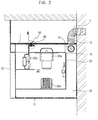
- Figure 2 is a cross-sectional view of the wall-mounted type microwave oven shown in Figure 1, which is installed to a wall in a kitchen;
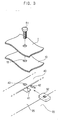
- Figure 3 is an exploded perspective view of portion III of Figure 2; and
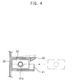
- Figure 4 is a plan cross-sectional view of a seat piece, a hook piece and a nut, according to the embodiment of the present invention.
-
- As shown in Figures 1 and 2, the wall-mounted type microwave oven according to the embodiment of the present invention is installed to a lower surface of an installation base "I" provided at a ceiling or a kitchen cabinet, which is positioned over a gas oven range (not shown). The wall-mounted type microwave oven is located at an upper surface thereof with an outer duct D, which is connected to the wall-mounted type microwave oven through the ceiling or the kitchen cabinet, so as to guide exhaust gas and food odors generated from the gas oven range positioned therebelow, to the outside.
- The wall-mounted type microwave oven includes an
outer cabinet 10 defining an outer appearance of the wall-mounted type microwave oven, and aninner cabinet 20 disposed in theouter cabinet 10 with a predetermined spacing therebetween, so as to enable the predetermined spacing to serve as aninner duct 30 to guide contaminated air therethrough. - The
inner cabinet 20 includes a cooking chamber 21 to cook foods therein, and anelectric component compartment 22 to receive various electric components, the cooking chamber 21 and theelectric component compartment 22 being isolated from each other. The cooking chamber 21 is opened and closed by adoor 23 hingedly coupled to a front surface of the cooking chamber 21. Theelectric component compartment 22 includes at a front surface thereof acontrol panel 24 to control various operations of the wall-mounted type microwave oven, which is positioned adjacent to thedoor 23. - The
electric component compartment 22 includes electric components such as amagnetron 22a to generate high-frequency electromagnetic waves into the cooking chamber 21, ahigh voltage transformer 22b to apply high voltage to themagnetron 22a, and acooling fan 22c to cool the electric components received in theelectric component compartment 22. - A lower panel, which defines a lower surface of the
outer cabinet 10, includes at sides thereofintake ports 11, so as to introduce the contaminated air containing exhaust gas and the food odors generated from the gas oven range positioned therebelow, into theouter cabinet 10. An upper panel, which defines an upper surface of theouter cabinet 10, includes anexhaust port 12, so as to exhaust the contaminated air introduced into theouter cabinet 10, to the outside. - The
inner duct 30 defined between theouter cabinet 10 and theinner cabinet 20 extends from under theinner cabinet 20 to theexhaust port 12 through a rear surface of theinner cabinet 20, so as to guide the contaminated air introduced through theintake port 11 to theexhaust port 12. Theouter cabinet 10 is provided at a rear and upper portion thereof with afan motor 13 to generate a turning force, and a pair ofexhaust fans 14 joined to driving shafts of thefan motor 13 to generate a suction force. - Thus the contaminated air, generated from the gas oven range, is introduced into the
outer cabinet 10 through theintake port 11 by the suction force caused by thefan motor 13 and theexhaust fans 14, and is guided to the outer duct D through theinner duct 30 and theexhaust port 12, thereby allowing the contaminated air to be exhausted to the outside. - As shown in Figure 3, to install the wall-mounted type microwave oven to the installation base I provided at a ceiling or a cabinet, for example, in a kitchen, the
inner cabinet 20 is provided at an upper surface thereof with ahanger member 40, which laterally extends parallel to the installation base I. Furthermore, the wall-mounted type microwave oven includes afastening device 50 to secure thehanger member 40 to the installation base I. - The
hanger member 40 secures theinner cabinet 20 to the installation base I together with theouter cabinet 10. Thehanger member 40 extends rearwardly from an upper end of apartition plate 25, which is located at an upper portion of theelectric component compartment 22 to guide air introduced into theouter cabinet 10 toward theelectric component compartment 22. - The
fastening device 50 comprises abolt 51 which sequentially passes through the installation base I, theouter cabinet 10 and thehanger member 40, and anut 52 which is disposed on a lower surface of thehanger member 40 and engages with thebolt 51 to secure thehanger member 40 and theouter cabinet 10 to the installation base I. To allow thebolt 51 to pass through theouter cabinet 10, theouter cabinet 10 is formed with a first throughhole 15, and thehanger member 40 is formed with a second throughhole 43. - The
hanger member 40 includes aseat piece 41 extending downwardly from the hanger member to allow thenut 52 to be placed thereon, and aresilient hook piece 42 to allow thenut 52 to be precisely seated on theseat piece 41 and to prevent the nut seated on theseat piece 41 from being separated therefrom. - The
seat piece 41 extends downwardly from thehanger member 40 and is laterally bent to have an "L"-shaped form, so that an end of theseat piece 41 is spaced from theresilient hook piece 42. Theseat piece 41 is formed at about its midpoint with acut portion 41a, so as to allow thebolt 51 to pass through theseat piece 41. Theresilient hook piece 42 is positioned at an opening side of theseat piece 41 to allow thenut 52 to be stably disposed therebetween. - The
nut 52 may comprise a square nut to prevent thenut 52 from rotating with respect to theseat piece 41 and theresilient hook piece 42. - Accordingly, when the
nut 52, which is square, is inserted between theseat piece 41 and theresilient hook piece 42 by an external force, theresilient hook piece 42 is resiliently deformed and then restored to a normal state thereof, thereby holding thenut 52 in place. After thenut 52 is completely inserted between theseat piece 41 and theresilient hook piece 42, thenut 52 cannot be separated from theseat piece 41. In this state, thenut 52 engages with thebolt 51 passed through the installation base I, theouter cabinet 10, and thehanger member 40. Thus, theouter cabinet 10 and theinner cabinet 20 is firmly securable to the installation base I in a suspended state. - Although the
hanger member 40 is integrally formed with and extends upwardly from theinner cabinet 20, thehanger member 40 may extend from various parts provided on the upper surface of theinner cabinet 20. - An operation of installing the wall-mounted type microwave oven according to the embodiment of the present invention will now be described in detail.
- First, when the
nut 52 is inserted between theseat piece 41 and theresilient hook piece 42 by the external force, theresilient hook piece 42 is resiliently deformed. After thenut 52 is stably seated on theseat piece 41, theresilient hook piece 42 is resiliently restored to the normal position thereof, thereby preventing thenut 52 from being separated from theseat piece 41. - Subsequently, the wall-mounted type microwave oven is positioned under the installation base I. The
bolt 51 is passed through the first throughholes 15 of the installation base I and theouter cabinet 10 and the second throughhole 43 of thehanger member 40, and then is rotated to engage with thenut 52 disposed on theseat piece 41. Since thenut 52 is formed into a square shape to cause opposite sides thereof to be in contact with theseat piece 41 and theresilient hook piece 42, a rotation of thenut 52 is prevented. As thebolt 51 rotates, thebolt 51 is tightly fastened to thenut 52. Therefore, theinner cabinet 20 as well as theouter cabinet 10 is firmly secured to the installation base I by thehanger member 40 and thefastening device 50. - As is apparent from the above description, a wall-mounted type microwave oven having a hanger member enables an inner cabinet as well as an outer cabinet of the wall-mounted type microwave oven to be secured to an installation area in a kitchen. Therefore, since a weight of the wall-mounted type microwave oven is evenly distributed to the inner and outer cabinets, a deformation of the outer cabinet is prevented.
- In addition, since the wall-mounted type microwave oven enables a nut to be held on a hanger member extending from a partition plate defining a flow path to cool an electric component compartment without additional parts, a production cost of the wall-mounted type microwave oven is reduced.
- Although a few preferred embodiments have been shown and described, it will be appreciated by those skilled in the art that various changes and modifications might be made without departing from the scope of the invention, as defined in the appended claims.
- Attention is directed to all papers and documents which are filed concurrently with or previous to this specification in connection with this application and which are open to public inspection with this specification, and the contents of all such papers and documents are incorporated herein by reference.
- All of the features disclosed in this specification (including any accompanying claims, abstract and drawings), and/or all of the steps of any method or process so disclosed, may be combined in any combination, except combinations where at least some of such features and/or steps are mutually exclusive.
- Each feature disclosed in this specification (including any accompanying claims, abstract and drawings) may be replaced by alternative features serving the same, equivalent or similar purpose, unless expressly stated otherwise. Thus, unless expressly stated otherwise, each feature disclosed is one example only of a generic series of equivalent or similar features.
- The invention is not restricted to the details of the foregoing embodiment(s). The invention extends to any novel one, or any novel combination, of the features disclosed in this specification (including any accompanying claims, abstract and drawings), or to any novel one, or any novel combination, of the steps of any method or process so disclosed.
Claims (23)
- A wall-mounted type microwave oven to be secured to an installation base, comprising:an outer cabinet (10) defining an outer appearance of the wall-mounted type microwave oven;an inner cabinet (20) disposed in the outer cabinet (10) with a predetermined spacing therebetween, and including a cooking chamber to cook foods therein and an electric component compartment to receive electric components, the cooking chamber and the electric component compartment being isolated from each other;a hanger member (40) extending from the inner cabinet (20) to allow the inner cabinet (20) to be secured to the installation base; anda fastening device (50) to secure the hanger member (40) to the installation base.
- The wall-mounted type microwave oven as set forth in claim 1, wherein the fastening device (50) comprises:a nut (52); anda bolt (51) passing through the installation base, the outer cabinet (10) and the hanger member (40), in sequence and the nut (52) engaging with the bolt (51).
- The wall-mounted type microwave oven as set forth in claim 2, wherein the hanger member (40) comprises:a seat piece (41) on which the nut (52) is seated; anda resilient hook piece (42) to allow the nut (52) to be seated on the seat piece (41) and to prevent the nut (52) from separating from the seat piece (41).
- The wall-mounted type microwave oven as set forth in claim 3, wherein the seat piece (41) extends downwardly from a lower surface of the hanger member (40) and is laterally bent to have an "L"-shaped section, as a bent portion, such that the nut (52) is seatable on the bent portion, and wherein the resilient hook piece (42) is positioned at an opening side of the seat piece (41) to prevent the nut (52) from separating from the seat piece (41).
- The wall-mounted type microwave oven as set forth in claim 4, wherein the nut (52) has a square shape, which is in contact with the seat piece (41) and the resilient hook piece (42) at sides thereof, so as to prevent the nut (52) from rotating when the bolt (51) engages therewith.
- The wall-mounted type microwave oven as set forth in any preceding claim, further comprising:wherein the hanger member (40) extends from the partition plate (25), which is attached to an upper and front portion of the inner cabinet (20) defining the electric component compartment (22) to define a flow path to cool the electric component compartment (22).a partition plate (25);
- A wall-mounted type microwave oven mountable to an installation base, comprising:an outer cabinet (10) defining an outer appearance of the wall-mounted type microwave oven;an inner cabinet (20) disposed in the outer cabinet (10) with a predetermined spacing therebetween; anda hanger unit (40) attaching to the inner and outer cabinets and the installation base to prevent a deformation of the outer cabinet (10).
- A wall-mounted type microwave oven mountable to an installation base, comprising:an outer cabinet (10) defining an outer appearance of the wall-mounted type microwave oven;an inner cabinet (20) disposed in the outer cabinet (10) with a predetermined spacing therebetween; anda hanger unit (40) attaching directly to the inner cabinet (20) and the installation base to prevent a deformation of the outer cabinet (10).
- The wall-mounted type microwave oven as set forth in claim 8, wherein the hanger unit (40) comprises:a hanger member (40) extending from the inner cabinet (20) to allow the inner cabinet (20) to be secured to the installation base; anda fastening device (50) to secure the hanger member (40) to the installation base.
- The wall-mounted type microwave oven as set forth in claim 9, wherein the fastening device (50) comprises:a nut (52); anda bolt (51) passing through the installation base, the outer cabinet (10) and the hanger member (40), in sequence and the nut (52) engaging with the bolt (51).
- The wall-mounted type microwave oven as set forth in claim 10, wherein the hanger member (40) comprises:a seat piece (41) on which the nut (52) is seated; anda hook piece to position the nut (52) on the seat piece (41) and to prevent the nut (52) from separating from the seat piece (41).
- The wall-mounted type microwave oven as set forth in claim 11, wherein the seat piece (41) extends from a lower surface of the hanger member (40) to seat the nut (52) thereon, and the hook piece is positioned adjacent to the nut (52) when the nut (52) is seated on the seat piece (41) and the nut (52) has at least one flat side communicating with the hook piece to prevent the nut (52) from rotating when the nut (52) is seated on the seat piece (41).
- The wall-mounted type microwave oven as set forth in claim 12, wherein the nut (52) has a non-circular shape, which is in contact with the seat piece (41) and the hook piece at sides thereof, so as to prevent the nut (52) from rotating when the bolt (51) engages therewith.
- The wall-mounted type microwave oven as set forth in any of claims 9 to 13, wherein the hanger unit (40) further comprises:a partition plate (25), wherein the hanger member (40) extends from the partition plate (25), which is attached to an upper and front portion of the inner cabinet (20).
- The wall-mounted type microwave oven as set forth in any of claims 9 to 14, wherein the hanger member (40) laterally extends parallel to the installation base.
- The wall-mounted type microwave oven as set forth in any of claims 9 to 15, wherein:the inner cabinet (20) comprises:an electric component compartment (22); andthe hanger member (40) secures the inner cabinet (20) to the installation base together with the outer cabinet (10) and guides air introduced into the outer cabinet (10) toward the electric component compartment (22).
- The wall-mounted type microwave oven as set forth in any of claims 11 to 16 wherein the seat piece (41) is an "L"-shaped section.
- The wall-mounted type microwave oven as set forth in any of claims 11 to 17 wherein the seat piece (41) is formed at about a midpoint thereof with a cut portion so as to allow the bolt (51) to pass through the seat piece (41).
- The wall-mounted type microwave oven as set forth in any of claims 9 to 18, wherein the hanger member (40) is integrally formed with and extends from the inner cabinet (20).
- The wall-mounted type microwave oven as set forth in any of claims 9 to 19, wherein the hanger member (40) extends upwardly from an upper surface of the inner cabinet (20).
- A wall-mounted type microwave oven mountable to an installation base, comprising:an outer cabinet (10) defining an outer appearance of the wall-mounted type microwave oven;an inner cabinet (20) disposed in the outer cabinet (10); anda hanger unit (40) attaching between the installation base and the inner cabinet (20) such that a weight of the wall-mounted type microwave oven is evenly distributed to the inner and outer cabinets.
- A wall-mounted type microwave oven mountable to an installation base, comprising:an outer cabinet (10) defining an outer appearance of the wall-mounted type microwave oven;an inner cabinet (20) disposed in the outer cabinet (10) with a predetermined spacing therebetween;an electric component compartment (22) including electric components therein to supply microwaves thereby;a partition plate (25) disposed between the inner and outer cabinets and defining a flow path to cool the electric components in the electric component compartment (22);a fastener; anda hanger member (40) extending from and fastened to the partition plate (25) by the fastener and attached to the installation base.
- A wall-mounted type microwave oven mountable to an installation base, comprising:outer enclosure means for defining an outer appearance of the wall-mounted type microwave oven;inner enclosure means disposed in the outer enclosure means with a predetermined spacing therebetween for cooking food therein; andhanger means for attaching directly to the inner enclosure means and the installation base to prevent a deformation of the outer enclosure means.
Applications Claiming Priority (2)
| Application Number | Priority Date | Filing Date | Title |
|---|---|---|---|
| KR2003001429 | 2003-01-09 | ||
| KR10-2003-0001429A KR100487159B1 (en) | 2003-01-09 | 2003-01-09 | Wall-mounted type microwave oven |
Publications (2)
| Publication Number | Publication Date |
|---|---|
| EP1437924A1 true EP1437924A1 (en) | 2004-07-14 |
| EP1437924B1 EP1437924B1 (en) | 2006-12-20 |
Family
ID=32501489
Family Applications (1)
| Application Number | Title | Priority Date | Filing Date |
|---|---|---|---|
| EP03257319A Expired - Lifetime EP1437924B1 (en) | 2003-01-09 | 2003-11-19 | Wall-mounted type microwave oven |
Country Status (6)
| Country | Link |
|---|---|
| US (1) | US6894259B2 (en) |
| EP (1) | EP1437924B1 (en) |
| JP (1) | JP3798399B2 (en) |
| KR (1) | KR100487159B1 (en) |
| CN (1) | CN1242210C (en) |
| DE (1) | DE60310516T2 (en) |
Families Citing this family (6)
| Publication number | Priority date | Publication date | Assignee | Title |
|---|---|---|---|---|
| KR20040036090A (en) * | 2002-10-23 | 2004-04-30 | 한라공조주식회사 | Structure for mounting nut of front end module in vehicle |
| CN111671322B (en) * | 2020-06-22 | 2022-03-22 | 广东美的厨房电器制造有限公司 | Baking oven |
| US11864296B2 (en) | 2020-11-04 | 2024-01-02 | Midea Group Co., Ltd. | Mounting arrangement for over-the-range cooking appliance |
| US12064033B2 (en) | 2021-06-21 | 2024-08-20 | Midea Group Co., Ltd. | Mounting bracket assembly for appliance |
| US12366365B2 (en) | 2021-06-21 | 2025-07-22 | Midea Group Co., Ltd. | Mounting bracket for over-the-range cooking appliance |
| US12121147B2 (en) | 2021-06-21 | 2024-10-22 | Midea Group Co., Ltd. | Mounting bracket for over-the-range cooking appliance with drill guide |
Citations (3)
| Publication number | Priority date | Publication date | Assignee | Title |
|---|---|---|---|---|
| US4666113A (en) * | 1985-04-03 | 1987-05-19 | Sanyo Electric Co. Ltd. | Device for mounting cooking apparatus |
| US6222171B1 (en) * | 1998-10-08 | 2001-04-24 | Sanyo Electric Co., Ltd. | Cooking appliance that can be easily installed by small man labor |
| US20020050491A1 (en) * | 2000-10-26 | 2002-05-02 | Kim An-Sik | Wall-mounted microwave oven |
Family Cites Families (8)
| Publication number | Priority date | Publication date | Assignee | Title |
|---|---|---|---|---|
| JPS54153064U (en) * | 1978-04-18 | 1979-10-24 | ||
| US4313043A (en) * | 1978-08-21 | 1982-01-26 | General Electric Company | Combination microwave oven and exhaust vent and installation mounting method therefor |
| JPS62143113U (en) * | 1986-03-04 | 1987-09-09 | ||
| JPS6349409U (en) * | 1986-09-12 | 1988-04-04 | ||
| JP2831879B2 (en) * | 1992-07-21 | 1998-12-02 | 株式会社東芝 | Mounting device and mounting method for cooking device |
| US5286940A (en) * | 1992-08-28 | 1994-02-15 | Leeds Harlan S | Microwave oven break away element trim kit |
| US5967634A (en) * | 1997-07-14 | 1999-10-19 | Whirlpool Corporation | Support base for a built-in oven |
| KR19990032462A (en) * | 1997-10-18 | 1999-05-15 | 윤종용 | Suspension Microwave Support Device |
-
2003
- 2003-01-09 KR KR10-2003-0001429A patent/KR100487159B1/en not_active Expired - Fee Related
- 2003-07-24 US US10/625,555 patent/US6894259B2/en not_active Expired - Fee Related
- 2003-11-06 CN CNB2003101036430A patent/CN1242210C/en not_active Expired - Fee Related
- 2003-11-13 JP JP2003384240A patent/JP3798399B2/en not_active Expired - Fee Related
- 2003-11-19 DE DE60310516T patent/DE60310516T2/en not_active Expired - Lifetime
- 2003-11-19 EP EP03257319A patent/EP1437924B1/en not_active Expired - Lifetime
Patent Citations (3)
| Publication number | Priority date | Publication date | Assignee | Title |
|---|---|---|---|---|
| US4666113A (en) * | 1985-04-03 | 1987-05-19 | Sanyo Electric Co. Ltd. | Device for mounting cooking apparatus |
| US6222171B1 (en) * | 1998-10-08 | 2001-04-24 | Sanyo Electric Co., Ltd. | Cooking appliance that can be easily installed by small man labor |
| US20020050491A1 (en) * | 2000-10-26 | 2002-05-02 | Kim An-Sik | Wall-mounted microwave oven |
Also Published As
| Publication number | Publication date |
|---|---|
| JP3798399B2 (en) | 2006-07-19 |
| CN1517601A (en) | 2004-08-04 |
| JP2004219056A (en) | 2004-08-05 |
| KR20040064130A (en) | 2004-07-16 |
| DE60310516D1 (en) | 2007-02-01 |
| CN1242210C (en) | 2006-02-15 |
| KR100487159B1 (en) | 2005-05-04 |
| EP1437924B1 (en) | 2006-12-20 |
| US6894259B2 (en) | 2005-05-17 |
| US20040134909A1 (en) | 2004-07-15 |
| DE60310516T2 (en) | 2007-09-27 |
Similar Documents
| Publication | Publication Date | Title |
|---|---|---|
| US4313043A (en) | Combination microwave oven and exhaust vent and installation mounting method therefor | |
| EP3479027B1 (en) | Cooking appliance | |
| US20100229847A1 (en) | Convection cooking appliance with circular air flow system | |
| CN1517593A (en) | Micro-wave oven | |
| US20240015859A1 (en) | Cooking device | |
| US6852963B2 (en) | Wall-mounted type microwave oven | |
| US20020050491A1 (en) | Wall-mounted microwave oven | |
| EP1437924B1 (en) | Wall-mounted type microwave oven | |
| US6737622B1 (en) | Wall-mounted type microwave oven | |
| EP1437922B1 (en) | Cooking appliance and a motor mounting unit therefore | |
| KR20050074676A (en) | Wall mounted type microwave oven | |
| US6717122B2 (en) | Wall-mounted microwave oven and structure for removing magnetron | |
| US20240353111A1 (en) | Brace for an oven appliance | |
| US7271373B2 (en) | Microwave oven | |
| JPH0674470A (en) | Heating cooker | |
| EP1437923A2 (en) | Microwave oven | |
| KR101652999B1 (en) | Microwave oven having hood | |
| KR200386253Y1 (en) | Microwave oven with hood | |
| JPS60105841A (en) | Composite heating cooker | |
| KR19980036834U (en) | Over the microwave thermostat installation structure | |
| KR19980067681A (en) | Fixture for duct for microwave | |
| KR19990014041U (en) | Locking device installation structure of microwave oven | |
| KR20080002115A (en) | Microwave | |
| KR20050076214A (en) | Wall mounting type microwave oven | |
| KR19990033948A (en) | Fixing Device for High Voltage Capacitor for Microwave Oven |
Legal Events
| Date | Code | Title | Description |
|---|---|---|---|
| PUAI | Public reference made under article 153(3) epc to a published international application that has entered the european phase |
Free format text: ORIGINAL CODE: 0009012 |
|
| 17P | Request for examination filed |
Effective date: 20031210 |
|
| AK | Designated contracting states |
Kind code of ref document: A1 Designated state(s): AT BE BG CH CY CZ DE DK EE ES FI FR GB GR HU IE IT LI LU MC NL PT RO SE SI SK TR |
|
| AX | Request for extension of the european patent |
Extension state: AL LT LV MK |
|
| AKX | Designation fees paid |
Designated state(s): DE FR GB |
|
| GRAP | Despatch of communication of intention to grant a patent |
Free format text: ORIGINAL CODE: EPIDOSNIGR1 |
|
| GRAS | Grant fee paid |
Free format text: ORIGINAL CODE: EPIDOSNIGR3 |
|
| GRAA | (expected) grant |
Free format text: ORIGINAL CODE: 0009210 |
|
| AK | Designated contracting states |
Kind code of ref document: B1 Designated state(s): DE FR GB |
|
| REG | Reference to a national code |
Ref country code: GB Ref legal event code: FG4D |
|
| REF | Corresponds to: |
Ref document number: 60310516 Country of ref document: DE Date of ref document: 20070201 Kind code of ref document: P |
|
| ET | Fr: translation filed | ||
| PLBE | No opposition filed within time limit |
Free format text: ORIGINAL CODE: 0009261 |
|
| STAA | Information on the status of an ep patent application or granted ep patent |
Free format text: STATUS: NO OPPOSITION FILED WITHIN TIME LIMIT |
|
| 26N | No opposition filed |
Effective date: 20070921 |
|
| PGFP | Annual fee paid to national office [announced via postgrant information from national office to epo] |
Ref country code: FR Payment date: 20141023 Year of fee payment: 12 Ref country code: DE Payment date: 20141021 Year of fee payment: 12 Ref country code: GB Payment date: 20141021 Year of fee payment: 12 |
|
| REG | Reference to a national code |
Ref country code: DE Ref legal event code: R119 Ref document number: 60310516 Country of ref document: DE |
|
| GBPC | Gb: european patent ceased through non-payment of renewal fee |
Effective date: 20151119 |
|
| REG | Reference to a national code |
Ref country code: FR Ref legal event code: ST Effective date: 20160729 |
|
| PG25 | Lapsed in a contracting state [announced via postgrant information from national office to epo] |
Ref country code: DE Free format text: LAPSE BECAUSE OF NON-PAYMENT OF DUE FEES Effective date: 20160601 Ref country code: GB Free format text: LAPSE BECAUSE OF NON-PAYMENT OF DUE FEES Effective date: 20151119 |
|
| PG25 | Lapsed in a contracting state [announced via postgrant information from national office to epo] |
Ref country code: FR Free format text: LAPSE BECAUSE OF NON-PAYMENT OF DUE FEES Effective date: 20151130 |