EP1437899A2 - Method and device for transmitting information in mobile communication mode - Google Patents
Method and device for transmitting information in mobile communication mode Download PDFInfo
- Publication number
- EP1437899A2 EP1437899A2 EP02768234A EP02768234A EP1437899A2 EP 1437899 A2 EP1437899 A2 EP 1437899A2 EP 02768234 A EP02768234 A EP 02768234A EP 02768234 A EP02768234 A EP 02768234A EP 1437899 A2 EP1437899 A2 EP 1437899A2
- Authority
- EP
- European Patent Office
- Prior art keywords
- mobile
- repeater
- communication means
- mobile communication
- radiation
- Prior art date
- Legal status (The legal status is an assumption and is not a legal conclusion. Google has not performed a legal analysis and makes no representation as to the accuracy of the status listed.)
- Granted
Links
Images


Classifications
-
- H—ELECTRICITY
- H04—ELECTRIC COMMUNICATION TECHNIQUE
- H04B—TRANSMISSION
- H04B7/00—Radio transmission systems, i.e. using radiation field
-
- H—ELECTRICITY
- H04—ELECTRIC COMMUNICATION TECHNIQUE
- H04W—WIRELESS COMMUNICATION NETWORKS
- H04W4/00—Services specially adapted for wireless communication networks; Facilities therefor
- H04W4/12—Messaging; Mailboxes; Announcements
-
- H—ELECTRICITY
- H04—ELECTRIC COMMUNICATION TECHNIQUE
- H04W—WIRELESS COMMUNICATION NETWORKS
- H04W88/00—Devices specially adapted for wireless communication networks, e.g. terminals, base stations or access point devices
- H04W88/02—Terminal devices
-
- H—ELECTRICITY
- H04—ELECTRIC COMMUNICATION TECHNIQUE
- H04W—WIRELESS COMMUNICATION NETWORKS
- H04W88/00—Devices specially adapted for wireless communication networks, e.g. terminals, base stations or access point devices
- H04W88/02—Terminal devices
- H04W88/04—Terminal devices adapted for relaying to or from another terminal or user
Definitions
- the invention relates to wireless communications in general and particularly to personal radio communications, and is applicable in a mobile telephone communications system.
- Most of conventional apparatuses for transmitting a message in a mobile communications system comprise a transceiver coupled to a control unit and including an emitter, such as a transceiver antenna (US Patent No. 5,530,736 A, IPC H04Q 7/20, 1994).
- an emitter such as a transceiver antenna
- a disadvantage of the mentioned and similar radiotelephones is that the electromagnetic radiation affects the user's (subscriber) health, and in particular the radiation acts on his/her head causing, in particular, cancer diseases.
- decimeter range frequency (900-1800 MHz), which frequency, at a radiation power of about one Watt and practically a zero distance between a mobile communication means, such as a radiotelephone, and the user's head, is capable of creating in the temporal bone area a power density 10-100 times exceeding the permitted values.
- a method of transmitting a message in a mobile communications system including: transmitting, by a mobile communication means, such as a radiotelephone having a first subscriber or identification number and an input device and a display, an electromagnetic radiation encoded by the message, e.g.
- said electromagnetic radiation having predetermined values of electromagnetic radiation parameters, and receiving, by the mobile communication means from a base transceiving station coupled with a first subscriber or identification number logging means, an electromagnetic energy flux having predetermined parameters and modulated by transmitted data; generating, in the mobile communication means, a message-encoded auxiliary radiation, and using, for each mobile communication means, at least one mobile repeater having a memory; said repeater receiving and processing the auxiliary radiation for predetermined values of quality estimates of communication between the mobile communication means and the mobile repeater, or between the mobile repeater and the base transceiving station, and generating and transmitting said message-encoded electromagnetic radiation, and exchanging control and clock signals between the mobile communication means and the base transceiving station (PCT Application WO 00/18040, March 30, 2000).
- the method is implemented in an apparatus for transmitting a message in a mobile communications system, including one or more base transceiving stations and a mobile communication means.
- the mobile communication means includes, coupled to a central controller, a radiotelephone transceiver and an auxiliary radiation transceiver matched over auxiliary communication channels with a mobile repeater including a repeater controller coupled to an internal memory of the mobile repeater, the mobile repeater being a bilateral mobile repeater whose internal memory stores a subscriber number of the mobile repeater, the mobile repeater comprising, coupled to the repeater controller, at least one bilateral radiotelephone transceiver and one bilateral auxiliary radiation transceiver, each of them being matched by its parameters with the base transceiving station and the auxiliary radiation transceiver of the mobile communication means, respectively.
- the object of the present invention is to eliminate impact of the additional delay on reliability of the system operation.
- the object is attained in accordance with the invention by transmitting, by a mobile communication means, such as a radiotelephone having a first subscriber or identification number and an input device and a display, an electromagnetic radiation encoded by the message, e.g. by modulation, said electromagnetic radiation having predetermined values of electromagnetic radiation parameters; and receiving, by the mobile communication means from a base transceiving station coupled with a first subscriber or identification number logging means, an electromagnetic energy flux having predetermined parameters and modulated by transmitted data; generating, in the mobile communication means, a message-encoded auxiliary radiation; and using for each mobile communication means at least one mobile repeater having a memory; said mobile repeater receiving and processing the auxiliary radiation for predetermined values of quality estimates of communication between the mobile communication means and the mobile repeater, or between the mobile repeater and the base transceiving station, and generating and transmitting said message-encoded electromagnetic radiation; exchanging control and clock signals between the mobile communication means and the base transceiving station; storing, in the mobile repeater memory, a
- the method can be implemented in an apparatus having one or more base transceiving stations and comprising a mobile communication means including, coupled to a central controller, a radiotelephone transceiver and an auxiliary radiation transceiver matched, over auxiliary communication channels, with a mobile repeater including a repeater controller coupled to an internal memory of the mobile repeater, said mobile repeater being a bilateral mobile repeater whose internal memory stores a subscriber or identification number of the mobile repeater, the mobile repeater comprising, coupled to the repeater controller, at least one bilateral radiotelephone transceiver and one bilateral auxiliary radiation transceiver, each of them being matched by its parameters with the base transceiving station and the auxiliary radiation transceiver of the mobile communication means, respectively.
- the method in accordance with the present invention first, eliminates the impact exerted on individual's health by a mobile communication means operating jointly with base transceiving stations and, second, improves quality of communication.
- Fig.1 represents a structural block diagram of a first embodiment of a mobile communications system wherein an apparatus for transmitting a message includes a mobile communication means 1, such as a mobile telephone having a transceiver antenna 2, and a bilateral mobile repeater 3 having a transceiver antenna 4, a receiver 5 for receiving an auxiliary radiation flux 6 emitted by the mobile communication means 1, and an emitter 7 of an additional auxiliary radiation flux 8.
- the additional auxiliary radiation can be generated by the bilateral mobile repeater 3 as a light, infrared or ultrasonic radiation modulated by the transmitted data.
- the system further includes one or more base transceiving stations (BTS) 9 having an antenna 10.
- BTS base transceiving stations
- the bilateral communication feature of the mobile repeater 3 provides the ability of retransmitting a message both from the mobile communication means 1 to the BTS 9, and from the BTS to the mobile communication means 1.
- the base transceiving station 9 is coupled with a first subscriber number logging means (not shown), such as any conventional means, e.g. Mobile Switching Center (MSC) comprising Home Location Registers (HLR) for GSM, and another devices.
- MSC Mobile Switching Center
- HLR Home Location Registers
- the bilateral mobile repeater 3 is implemented as a portable device located near a subscriber who has the mobile communication means 1, and intended to retransmit the auxiliary radiation flux 6, as well as the additional auxiliary radiation 8 from the bilateral mobile repeater. Process of transmission of a message-encoded, e.g.
- Fig.2 shows a structural block diagram of a mobile communications system wherein the auxiliary radiation is an electromagnetic radiation 15, and the additional auxiliary radiation is an electromagnetic radiation 16.
- the mobile communication means 1 has an additional antenna 17, and the bilateral mobile repeater 3 has an additional antenna 18.
- a similar repeater design is described in US Patent No. 4,539,706, and the system can use several mobile repeaters 3, each having a subscriber number of its own.
- two common transceiving antennas 19, 20 can be used (Fig.3).
- a duplex filter - a device for dividing a reception and transmission band - can be used.
- channels 11, 12, 13 and 14 are physical channels (representing e.g. a combination of time and frequency division channels and defined as a sequence of radio frequency channels with frequency hopping and time slots) and can also include logical control and clock channels (control signal transmission channels, common control channels, individual control channels, frequency control channel, multiple access channel, etc.) on which control and lock signals are exchanged between the BTS 9 and the mobile communication means 1 (channels 11, 12), or between the BTS 9 and the bilateral mobile repeater 3 (channels 13, 14). All of the signals are generated in a base station controller (BSC) coupled to the BTS 9.
- BSC base station controller
- Fig.4 shows functional block diagrams of a mobile communication means 1, such as a mobile radiotelephone, and a bilateral mobile repeater 3.
- the mobile radiotelephone comprises, connected via an interface 21 to a central controller 22, one or more transceivers 23, at least two of which are a radiotelephone transceiver and an auxiliary radiation transceiver.
- Each of the transceivers 23 includes at least an output unit (radio circuitry) 24 connected to an individual or common antenna 25.
- CPU central processor unit
- the bilateral mobile repeater 3 comprises, connected via an interface 28 to a repeater controller 29, one or more transceivers 30, at least two of which are a bilateral radiotelephone transceiver and a bilateral auxiliary radiation transceiver, each of then being matched by its parameters with the base transceiving station 9 and a respective auxiliary radiation transceiver 23, respectively.
- the aforementioned bilateral communication ability of a respective transceiver provides the capability of data reception from and transmission to only one of said means 1, 9.
- Each radio transmitter 30 includes at least an output unit 31 (radio circuitry) coupled to an individual or common antenna 32.
- a repeater controller 29, in turn, comprises a central logic unit (CLU) 33 connected to an internal memory 24 of the bilateral mobile repeater.
- CLU central logic unit
- Some embodiments can comprise electronic identification card reading means 35 coupled to the repeater controller.
- a similar means for reading from an identification card comprising e.g. a first subscriber or identification number can be included in the mobile communication means 1.
- the bilateral mobile repeater can further comprise an additional identification card reading means 36 coupled to the repeater controller 29.
- the identification card can be either a detachable or built-in unit.
- a respective bilateral auxiliary radiation transceiver can be a bilateral transceiver of light, infrared or ultrasonic radiation, and furthermore, one bilateral mobile repeater 3 can operate with several mobile communication means 1; a respective auxiliary radiation transceiver 23 of each mobile communication means 1 should shall be matched with a respective bilateral auxiliary radiation transceiver 30.
- channels 15 and 16 could be provided by such wireless communication standards as DECT, NTT Digital Cordless, CT2, Bluetooth.
- additional repeater controllers 29 suitable for the corresponding system, e.g. DECT system.
- An additional interface would be also needed to couple the DECT system to the standard used in the mobile repeater, e.g. GSM.
- Fig.5 is a flow chart illustrating how the apparatus functions. Reference numerals in blocks shown in the flow chart correspond to the following steps. 38 denotes the step “Generate and transmit enable signal”; 39 denotes the step “Establish connection”; 40 denotes the step “Estimate communication quality”; 41 denotes the decision step “Communication quality satisfies?"; 42 denotes the step “Indicate”; 43 denotes the step “Establish connection”; 44 denotes the decision step “Communication quality satisfies?”; 45 denotes the decision step “Repeater enabled?”; 46 denotes the step “Indicate”; 47 denotes the step “Generate instruction”; 48 denotes the step “Generate instruction”, 49 denotes the step “Generate instruction”; 50 denotes the decision step “Repeater enabled”?; 51 denotes the step “Indicate”; 52 denotes the step “Generate instruction”; 53 denotes the step "
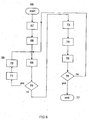
- Fig.6 is a flow chart illustrating how the radiotelephone can be disabled. Reference numerals in blocks shown in the flow chart correspond to the following steps. 67 denotes the step “Enter disable code”; 68 denotes the step “Enable radiotelephone”; 69 denotes the step “Make measurement”; 70 denotes the decision step “Radiation level exceeds the specified value?"; 71 denotes the step “Disable”; 72 denotes the step “Indicate”; 73 denotes the step “Indicate”; 74 denotes the step “Establish connection”; 75 denotes the step “Conversation”; 76 denotes the decision step "Conversation completed?”.
- the apparatus for transmitting a message in a mobile communications system operates in accordance with the algorithms shown in Figs.5 and 6.
- the algorithms are implemented using dedicated software stored both in the mobile communications system itself and in memory of the mobile means 1, 3.
- the operation starts (block 37) from enabling a mobile communication means 1. If the latter is a radiotelephone, step 37 comprises its enabling to generate and transmit a signal to enable a bilateral repeater 3 or to leave the stand-by mode (block 38).
- the signal can be transmitted by one of transceivers 23.
- connection is established (block 29) with a bilateral mobile repeater 3 using auxiliary radiations 6, 8, 15, 16.
- quality of communication over auxiliary radiation is estimated (block 40), and, if required, the bilateral mobile repeater parameters are shown on the display of the mobile communication means 1 (status of power supply of the bilateral mobile repeater, its location, etc.).
- Estimation of communication quality and transmission of above parameters can be accomplished by generating, in the mobile repeater 3, a specific signal which either transmits quality data of the signal received from the mobile communication means on the channel using auxiliary radiation, or is a signal per se, by which the communication quality is judged, but in the mobile communication means in this case.
- Estimation of signal quality is performed, as will be shown below, by standard methods using dedicated software after the signal has passed through an A/D converter which can be included in the central controller 22.
- a signal level is a standard function inherent in numerous mobile systems, e.g. CDMA and GSM mobile telephone communications systems. Signal is generally estimated after its detection and calculation of the signal-to-noise ratio integrated for a predetermined time period.
- the central controller 22 In the absence of the above transmission and reception processes shown by broken arrows 13 and 14 ("No" at the decision step 45) and when the quality estimate of the channels 6, 8, 14, 15 using auxiliary radiations is unsatisfactory (“No” at the decision step 40) the central controller 22 generates an instruction (step 47) to establish connection between the mobile communication means 1 and the BTS 9 on communication channels 11, 12 (step 58).
- quality estimate values of communication between the mobile communication means 1 and mobile repeater 3 are specified so that e.g. a message is received by the mobile communication means 1 from the base transceiving station by receiving an electromagnetic energy flux having predetermined parameters and modulated by transmitted data.
- the method of transmitting a message in a mobile communications system comprises: transmitting (broken dash arrow 11), by a mobile communication means having a first subscriber or identification number, an electromagnetic radiation encoded by the message, e.g. by modulation, the electromagnetic radiation having predetermined values of electromagnetic radiation parameters, and receiving (broken dash arrow 12), by the mobile communication means 1 from the base transceiving station 9 linked with first subscriber number logging means, an electromagnetic energy flux having predetermined parameters and modulated by transmitted data. If communication quality estimate on channels 11, 12 is unsatisfactory ("No" at the decision step 59) and if desired to repeat attempt to establish connection ("Yes" at the decision step 61), either the signal is retransmitted (step 38) or the communication is completed (step 64).
- Step 63 provides, first, transmission and reception of a message (e.g. as a conversation in duplex mode) on communication channels 11, 12, and step 62 provides communication of control and clock signals between the mobile communication means 1 and base transceiving station 9. If the quality estimate of channels 6, 8, 15, 16 using auxiliary radiations is satisfactory ("Yes" at the decision step 41), the repeater controller 29 generates instructions (step 43) to establish connection between the bilateral mobile repeater 3 and the BTS 9 on communication channels 13, 14.
- the channel quality estimate values for communication between the mobile communication means 1 and the mobile repeater 3 are specified so that messages are received by the mobile communication means by receiving from the mobile repeater an additional auxiliary radiation modulated by transmitted data.
- the central controller 22 generates an instruction (step 52) to establish connection between the mobile communication means 1 and the BTS 9 on communication channels 11, 12.
- step 55 the bilateral mobile repeater 3 receives from the base transceiving station 9 an electromagnetic energy flux having predetermined parameters and modulated by transmitted data, and the message is received by the mobile communication means by receiving from the mobile repeater 3 an additional auxiliary radiation 8, 16 modulated by transmitted data.
- BSS base station software
- step 56 can be performed to describe or re-address the 'call, or simply log a second subscriber number in a respective logging means connected to the BTS 9.
- connection is established automatically or by operator with the mobile repeater 3, with which control and clock signals are exchanged and through which the message is exchanged with radiotelephone 1.
- All of the above steps (re-addressing of the call, logging of a second number, etc.) associated with subscriber numbers can be also performed with other numbers used in a respective mobile communications system.
- such numbers include International Mobile Subscriber Identity (IMSI), International Mobile Equipment Identifier (IMEI), ISDN subscriber number.
- IMSI International Mobile Subscriber Identity
- IMEI International Mobile Equipment Identifier
- ISDN subscriber number The use of one of such numbers is possible, in particular when a unified subscriber number is assigned to the user.
- the mobile repeater can simultaneously generate another signals (steps 49, 54) instructing the controller 22 to perform the steps 47 and 52.
- Most of the aforementioned conditions can be indicated on the radiotelephone display, e.g. indication of respective modes (quality status of communication between the mobile communication means and the mobile repeater, quality status of communication between the mobile repeater and the base transceiving station, etc.) shown in Fig.5 in blocks 42, 46, 51 and 60.
- some mobile communication means and mobile repeaters can include the following additional functions or elements: a mobile repeater can provide audible or light signals (to locate the mobile repeater) when a corresponding key is pressed on the mobile communication means or when the mobile communication means outputs ring signal; a mobile repeater can provide audible or light signals when communication is unsatisfactory between the mobile repeater and the mobile communication means; direction towards the mobile repeater location can be indicated on the mobile communication means; a mobile repeater can be equipped with directional antennas 4, 18, 20 and systems for automatically orienting the antennas in the optimal direction; audible message can be sent to the user of the mobile communication means about status of a mobile repeater (battery discharge alarm, mobile repeater location signaling, signal of presence of shielding objects between the mobile repeater and the radiotelephone).
- An important service function provided by the invention is the ability of disabling the radiotelephone when power of electromagnetic radiation 11 exceeds a predetermined value.
- This function can be used e.g. by parents whose children may neglect the mobile repeater when talking over the radiotelephone.
- the level of electromagnetic radiation 11 having predetermined parameter values will be measured (step 69).
- the radiotelephone will be disabled (step 71) and appropriate indication will appear on its display (step 72). If the radiation level is smaller than the predetermined value ("No" at the decision step 70), appropriate indication is displayed (step 73) and connection is established with the BTS 9 (step 74) to accomplish conversation and communication of control and clock data; in this case during the conversation over the radiotelephone (step 75) the electromagnetic radiation level is tracked ("No" at the decision step 76), (step 69).
- the invention can be suitably used in particular in such communication fields as mobile telephone communication of all known standards (GSM, TDMA, JDC, CDMA, etc), trunking radiotelephone communications system; personal wireless communication radio stations.
- GSM Global System for Mobile Communications
- TDMA Time Division Multiple Access
- JDC JDC
- CDMA Code Division Multiple Access
- This invention can find its wide use also in the public places where persons using a mobile telephone communication can be present. In this case, such places are provided with multichannel mobile repeaters, each comprising, for example, a plurality of subscriber numbers and increased radiation power.
- multichannel mobile repeaters each comprising, for example, a plurality of subscriber numbers and increased radiation power.
Landscapes
- Engineering & Computer Science (AREA)
- Computer Networks & Wireless Communication (AREA)
- Signal Processing (AREA)
- Mobile Radio Communication Systems (AREA)
- Radio Relay Systems (AREA)
- Nitrogen And Oxygen Or Sulfur-Condensed Heterocyclic Ring Systems (AREA)
Abstract
Description
Claims (16)
- A method of transmitting a message in a mobile communications system, including the steps of:wherein the message being received by the mobile communication means by receiving from the mobile repeater an additional auxiliary radiation modulated by the transmitted data, and said exchanging of the control and clock signals being performed between the mobile repeater and the base transceiving station.transmitting by a mobile communication means, such as a radiotelephone having a first subscriber or identification number and an input device and a display, an electromagnetic radiation encoded by the message, for example by modulation, and having predetermined values of electromagnetic radiation parameters; andreceiving, by the mobile communication means from a base transceiving station coupled with a first subscriber or identification number logging means, an electromagnetic energy flux having predetermined parameters and modulated by transmitted data;generating, by the mobile communication means, a message-encoded auxiliary radiation; andusing, for each mobile communication means, at least one mobile repeater having a memory, said mobile repeater receiving and processing the auxiliary radiation for predetermined values of quality estimates of communication between the mobile communication means and the mobile repeater, or between the mobile repeater and the base transceiving station, and generating and transmitting said message-encoded electromagnetic radiation; andexchanging control and clock signals between the mobile communication means and the base transceiving station;storing, in the mobile repeater memory, a second subscriber or identification number, and connecting, for a predetermined value of said communication quality estimate, the mobile repeater to the base transceiving station, then receiving by the mobile repeater from the base transceiving station the electromagnetic energy flux having the predetermined parameters and modulated by the transmitted data;
- The method as claimed in claim 1, wherein a second subscriber or identification number is logged in said logging means for the predetermined value of said communication quality estimate.
- The method as claimed in claim 1, further comprising generating, by the mobile repeater, an additional auxiliary radiation as light or infrared radiation modulated by the transmitted data.
- The method as claimed in claim 1, further comprising generating, by the mobile repeater, an additional auxiliary radiation as ultrasound radiation modulated by the transmitted data.
- The method as claimed in claim 1, further comprising specifying such quality estimate values of communication between the mobile communication means and the mobile repeater, at which values the message is received by the mobile communication means by receiving from the repeater an additional auxiliary radiation modulated by the transmitted data.
- The method as claimed in claim 1, further comprising specifying such quality estimate values of communication between the mobile communication means and the mobile repeater, at which values the message is received by the mobile communication means by receiving from the base transceiving station the electromagnetic energy flux having the predetermined parameters and modulated by the transmitted data.
- The method as claimed in claim 1, further comprising disabling the transmission of the electromagnetic radiation having the predetermined values of the electromagnetic radiation parameters by entering a disable code in the mobile communication means via the input device.
- The method as claimed in claim 7, further comprising disabling the transmission of the electromagnetic radiation if the radiation level exceeds a predetermined value.
- The method as claimed in any one of claims 1 to 8, further comprising specifying such quality estimate values of the communication between the mobile communication means and the mobile repeater, or between the mobile repeater and the base transceiving station, at which values a signal is generated in the mobile repeater, after receiving the signal by the base transceiving station the message is received by the mobile communication means from the base transceiving station by receiving the electromagnetic energy flux with the predetermined parameters and modulated by the transmitted data.
- The method as claimed in any one of claims 1 to 8, further comprising indicating on the display of the mobile communication means, a quality status of communication between the mobile communication means and the mobile repeater.
- The method as claimed in any one of claims 1 to 8, further comprising indicating on the display of the mobile communication means, a quality status of communication between the mobile repeater and the base transceiving station.
- An apparatus for transmitting a message in a mobile communications system comprising one or more base transceiving stations and a mobile communication means, including, connected to a central controller, a radiotelephone transceiver and an auxiliary radiation transceiver matched, over auxiliary communication channels, with a mobile repeater including a repeater controller coupled to an internal memory of the mobile repeater, wherein the mobile repeater is a bilateral mobile repeater whose internal memory stores a subscriber or identification number of the mobile repeater, the mobile repeater comprising, connected to the repeater controller, at least one bilateral radiotelephone transceiver and one bilateral auxiliary radiation transceiver, each of them being matched by its parameters with the base transceiving station and with the auxiliary radiation transceiver of the mobile communication means, respectively.
- The apparatus as claimed in claim 12, wherein the bilateral auxiliary radiation transceiver is one of a bilateral light, an infrared or an ultrasonic radiation transceiver.
- The apparatus as claimed in claim 12, wherein the bilateral mobile repeater comprises an electronic identification card reading means connected to the repeater controller.
- The apparatus as claimed in claims 12, wherein the bilateral mobile repeater comprises an additional electronic identification card reading means connected to the repeater controller.
- The apparatus as claimed in any one of claims 12 to 15, comprising two or more mobile communication means, each having an auxiliary radiation transceiver matched with the bilateral auxiliary radiation transceiver.
Priority Applications (1)
| Application Number | Priority Date | Filing Date | Title |
|---|---|---|---|
| CY20131100360T CY1114876T1 (en) | 2001-09-12 | 2013-04-30 | METHOD AND APPLIANCE FOR TRANSFER OF INFORMATION IN MOBILE COMMUNICATION OPERATION |
Applications Claiming Priority (3)
| Application Number | Priority Date | Filing Date | Title |
|---|---|---|---|
| RU2001124924/09A RU2206959C2 (en) | 2001-09-12 | 2001-09-12 | Method and device for transmitting messages in mobile communication system |
| RU2001124924 | 2001-09-12 | ||
| PCT/RU2002/000424 WO2003024124A2 (en) | 2001-09-12 | 2002-09-12 | Method and device for transmitting information in mobile communication mode |
Publications (3)
| Publication Number | Publication Date |
|---|---|
| EP1437899A2 true EP1437899A2 (en) | 2004-07-14 |
| EP1437899A4 EP1437899A4 (en) | 2010-09-29 |
| EP1437899B1 EP1437899B1 (en) | 2013-01-30 |
Family
ID=20253093
Family Applications (1)
| Application Number | Title | Priority Date | Filing Date |
|---|---|---|---|
| EP02768234A Expired - Lifetime EP1437899B1 (en) | 2001-09-12 | 2002-09-12 | Method and device for transmitting information in mobile communication mode |
Country Status (11)
| Country | Link |
|---|---|
| US (1) | US7444116B2 (en) |
| EP (1) | EP1437899B1 (en) |
| KR (1) | KR100945885B1 (en) |
| AU (1) | AU2002332208A1 (en) |
| CY (1) | CY1114876T1 (en) |
| DK (1) | DK1437899T3 (en) |
| EA (1) | EA005556B1 (en) |
| ES (1) | ES2419163T3 (en) |
| PT (1) | PT1437899E (en) |
| RU (1) | RU2206959C2 (en) |
| WO (1) | WO2003024124A2 (en) |
Cited By (1)
| Publication number | Priority date | Publication date | Assignee | Title |
|---|---|---|---|---|
| CN104756417A (en) * | 2012-08-29 | 2015-07-01 | 瓦列里·菲利普维奇·伊凡诺夫 | Mobile communication method using mobile repeater |
Families Citing this family (40)
| Publication number | Priority date | Publication date | Assignee | Title |
|---|---|---|---|---|
| JP2003318810A (en) * | 2002-04-26 | 2003-11-07 | Kobe Steel Ltd | Radio data collection system and radio data repeater |
| JP2003324383A (en) * | 2002-05-07 | 2003-11-14 | Kddi Corp | Repeater device for wireless system |
| US7333829B2 (en) * | 2003-03-24 | 2008-02-19 | Quorum Systems | Multi-mode wireless bridge system and method using a single-radio transceiver |
| CN100551142C (en) * | 2003-08-11 | 2009-10-14 | 摩托罗拉公司 | A kind of method and device thereof that is used for from the wireless device forwarding information |
| US20090258639A1 (en) * | 2003-12-19 | 2009-10-15 | Nystroem Johan | Method, system and device for providing a robust wireless connection |
| EP1601213B1 (en) * | 2004-05-19 | 2006-05-03 | Swisscom Mobile AG | Method and system for automatic call forwarding |
| KR100617731B1 (en) * | 2004-06-19 | 2006-08-28 | 삼성전자주식회사 | Apparatus and method for transmitting and receiving a traffic notification message in a communication system |
| US8238287B1 (en) | 2004-10-06 | 2012-08-07 | Marvell International Ltd. | Method and apparatus for providing quality of service (QoS) in a wireless local area network |
| US8131209B1 (en) * | 2004-10-08 | 2012-03-06 | Marvell International Ltd. | Repeater configuration and management |
| US7233770B2 (en) * | 2005-03-07 | 2007-06-19 | Harris Corporation | Communications system using separate receive and transmit frequency hopping hopsets |
| RU2309544C2 (en) * | 2005-03-22 | 2007-10-27 | Игорь Владимирович Федоров | Device for transferring messages in mobile communication system |
| US8478262B2 (en) * | 2005-06-29 | 2013-07-02 | Koninklijke Philips Electronics, N.V. | Method and apparatus for delegating signal quality handover measuring of a user equipment in wireless communication to a neighbouring user equipment |
| JP2007028176A (en) * | 2005-07-15 | 2007-02-01 | Oki Electric Ind Co Ltd | Communication method and repeating device |
| JP4662353B2 (en) * | 2005-08-12 | 2011-03-30 | キヤノン株式会社 | Communication system, communication apparatus, communication control device, control program, and control method |
| IL170435B (en) * | 2005-08-22 | 2021-03-25 | Sela Nisim | Cellular communication system for reducing the effects of radiation emitted from cellular phone antennas |
| KR101128800B1 (en) * | 2005-11-11 | 2012-03-23 | 엘지전자 주식회사 | Method of Controlling Relay Communication |
| WO2007055544A2 (en) | 2005-11-11 | 2007-05-18 | Lg Electronics Inc. | Method of controlling relay communication |
| TWI313138B (en) * | 2005-12-08 | 2009-08-01 | Method, system and computer readable medium therefor adapted for wireless communication system | |
| ES2313232T3 (en) * | 2005-12-27 | 2009-03-01 | TCL & ALCATEL MOBILE PHONES LIMITED | PORTABLE COMMUNICATIONS EQUIPMENT FOR TELEPHONE AND MOBILE TELEVISION AND CORRESPONDING ACCESSORY. |
| US7570951B2 (en) * | 2006-02-06 | 2009-08-04 | Motorola, Inc. | Neighbor-assisted handover in mobile communications systems |
| JP5045029B2 (en) * | 2006-08-21 | 2012-10-10 | 富士通株式会社 | Wireless base station |
| US7990255B2 (en) * | 2006-11-02 | 2011-08-02 | Audiovox Corporation | Range extending positive repeater |
| US20080167072A1 (en) * | 2007-01-04 | 2008-07-10 | Viktors Berstis | System and method for providing telephone service access via a gateway telephone |
| KR101400715B1 (en) * | 2008-04-02 | 2014-05-29 | 연세대학교 산학협력단 | Apparatus and method for communication using cooperative tranmission and network coding transmission |
| US9351654B2 (en) | 2010-06-08 | 2016-05-31 | Alivecor, Inc. | Two electrode apparatus and methods for twelve lead ECG |
| US8509882B2 (en) | 2010-06-08 | 2013-08-13 | Alivecor, Inc. | Heart monitoring system usable with a smartphone or computer |
| GB201012865D0 (en) * | 2010-07-30 | 2010-09-15 | Freewave Ltd | Personal communications device |
| WO2014036436A1 (en) | 2012-08-30 | 2014-03-06 | Alivecor, Inc. | Cardiac performance monitoring system for use with mobile communications devices |
| WO2014074913A1 (en) | 2012-11-08 | 2014-05-15 | Alivecor, Inc. | Electrocardiogram signal detection |
| US9220430B2 (en) | 2013-01-07 | 2015-12-29 | Alivecor, Inc. | Methods and systems for electrode placement |
| WO2014145927A1 (en) | 2013-03-15 | 2014-09-18 | Alivecor, Inc. | Systems and methods for processing and analyzing medical data |
| RU2013128386A (en) * | 2013-06-21 | 2014-12-27 | Юрий Борисович Соколов | SECURE MOBILE COMMUNICATION DEVICE |
| US9247911B2 (en) | 2013-07-10 | 2016-02-02 | Alivecor, Inc. | Devices and methods for real-time denoising of electrocardiograms |
| WO2015089484A1 (en) | 2013-12-12 | 2015-06-18 | Alivecor, Inc. | Methods and systems for arrhythmia tracking and scoring |
| CN103906168A (en) * | 2014-04-11 | 2014-07-02 | 中广核工程有限公司 | Composite mobile communication method, terminal and system for nuclear power station |
| WO2016183515A1 (en) | 2015-05-13 | 2016-11-17 | Alivecor, Inc. | Discordance monitoring |
| US20180199326A1 (en) * | 2017-01-10 | 2018-07-12 | Nextivity, Inc. | Real time adaptation of a mobile repeater antenna pattern |
| RU2720351C1 (en) * | 2019-06-05 | 2020-04-29 | Общество с ограниченной ответственностью "ДиС ПЛЮС" | Mobile communication device, mobile repeater and method of using them |
| RU2734282C1 (en) * | 2020-03-24 | 2020-10-14 | Федеральное государственное бюджетное образовательное учреждение высшего образования "Владивостокский государственный университет экономики и сервиса" (ВГУЭС) | Cellular communication system |
| CN117396931A (en) | 2021-04-19 | 2024-01-12 | 米沃奇电动工具公司 | Systems and methods for tool signal expansion |
Family Cites Families (19)
| Publication number | Priority date | Publication date | Assignee | Title |
|---|---|---|---|---|
| US4012597A (en) * | 1975-11-24 | 1977-03-15 | Motorola, Inc. | Transmission trunk multichannel dispatch system with priority queuing |
| US4539706A (en) * | 1983-02-03 | 1985-09-03 | General Electric Company | Mobile vehicular repeater system which provides up-link acknowledgement signal to portable transceiver at end of transceiver transmission |
| US4882765A (en) | 1987-05-22 | 1989-11-21 | Maxwell Ray F | Data transmission system |
| SU1522417A1 (en) * | 1987-10-09 | 1989-11-15 | Предприятие П/Я Р-6120 | Communication system with message-relaying |
| SU1555881A1 (en) * | 1988-04-22 | 1990-04-07 | Московский энергетический институт | Communication device of ground stations |
| US5020091A (en) * | 1989-12-26 | 1991-05-28 | Motorola Inc. | Automatic new radiotelephone system registration notification |
| US5090051A (en) * | 1990-02-22 | 1992-02-18 | Motorola, Inc. | Radio communication system and method for connecting an incoming call to a wireless telephone |
| US5297142A (en) * | 1991-07-18 | 1994-03-22 | Motorola, Inc. | Data transfer method and apparatus for communication between a peripheral and a master |
| JPH05276098A (en) * | 1992-03-30 | 1993-10-22 | Casio Comput Co Ltd | Cordless phone base unit |
| US5371781A (en) * | 1993-09-30 | 1994-12-06 | At&T Corp. | System and method for identifying the incoming directory number when multiple directory numbers are assigned to one wireless device |
| GB2291564B (en) * | 1994-07-13 | 1999-02-10 | Nec Corp | Mobile communication for a mobile station near the boundary of or outside a service area of a base station |
| US5530736A (en) * | 1994-07-20 | 1996-06-25 | Bellsouth Corporation | Radiotelephone with multiple simultaneous telephone number identities |
| US6035178A (en) * | 1996-05-09 | 2000-03-07 | Ericsson Inc. | Satellite communication system for local-area coverage |
| FI111674B (en) * | 1996-10-31 | 2003-08-29 | Nokia Corp | User Connection |
| US6052558A (en) * | 1997-04-28 | 2000-04-18 | Motorola, Inc. | Networked repeater |
| US6285857B1 (en) * | 1997-05-01 | 2001-09-04 | At&T Corp. | Multi-hop telecommunications system and method |
| WO2000018040A1 (en) * | 1998-09-21 | 2000-03-30 | Valery Filippovich Ivanov | Method and device for transmitting a message in a mobile communication system |
| US6570858B1 (en) * | 1999-11-01 | 2003-05-27 | Motorola, Inc. | Satellite-based communications system with terrestrial repeater and method therefor |
| JP4573422B2 (en) * | 1999-11-30 | 2010-11-04 | シャープ株式会社 | Data communication apparatus, data communication system, and machine-readable recording medium storing program for realizing data communication method |
-
2001
- 2001-09-12 RU RU2001124924/09A patent/RU2206959C2/en active IP Right Revival
-
2002
- 2002-09-12 EA EA200400429A patent/EA005556B1/en not_active IP Right Cessation
- 2002-09-12 AU AU2002332208A patent/AU2002332208A1/en not_active Abandoned
- 2002-09-12 WO PCT/RU2002/000424 patent/WO2003024124A2/en not_active Ceased
- 2002-09-12 PT PT2768234T patent/PT1437899E/en unknown
- 2002-09-12 ES ES02768234T patent/ES2419163T3/en not_active Expired - Lifetime
- 2002-09-12 KR KR1020047003777A patent/KR100945885B1/en not_active Expired - Fee Related
- 2002-09-12 US US10/489,375 patent/US7444116B2/en not_active Expired - Lifetime
- 2002-09-12 DK DK02768234.3T patent/DK1437899T3/en active
- 2002-09-12 EP EP02768234A patent/EP1437899B1/en not_active Expired - Lifetime
-
2013
- 2013-04-30 CY CY20131100360T patent/CY1114876T1/en unknown
Cited By (1)
| Publication number | Priority date | Publication date | Assignee | Title |
|---|---|---|---|---|
| CN104756417A (en) * | 2012-08-29 | 2015-07-01 | 瓦列里·菲利普维奇·伊凡诺夫 | Mobile communication method using mobile repeater |
Also Published As
| Publication number | Publication date |
|---|---|
| RU2206959C2 (en) | 2003-06-20 |
| EP1437899B1 (en) | 2013-01-30 |
| CY1114876T1 (en) | 2016-12-14 |
| ES2419163T3 (en) | 2013-08-19 |
| WO2003024124A3 (en) | 2003-06-26 |
| AU2002332208A1 (en) | 2003-03-24 |
| US7444116B2 (en) | 2008-10-28 |
| WO2003024124A2 (en) | 2003-03-20 |
| US20040266340A1 (en) | 2004-12-30 |
| PT1437899E (en) | 2013-05-07 |
| DK1437899T3 (en) | 2013-05-13 |
| EP1437899A4 (en) | 2010-09-29 |
| KR20040044922A (en) | 2004-05-31 |
| EA200400429A1 (en) | 2004-08-26 |
| EA005556B1 (en) | 2005-04-28 |
| KR100945885B1 (en) | 2010-03-05 |
Similar Documents
| Publication | Publication Date | Title |
|---|---|---|
| US7444116B2 (en) | Method of transmitting a message in a mobile communications system using a mobile repeater | |
| US6292471B1 (en) | Power control for mobile wireless communication system | |
| US6987978B2 (en) | Wireless communication restriction device, repeater and base station | |
| KR100484466B1 (en) | Cellular telephone with simultaneous radio and cellular communication | |
| JP4971375B2 (en) | Method for operating mobile radio system in restricted local area, radio station, mobile radio terminal device and mobile radio system | |
| US6477384B2 (en) | Checking the presence of mobile stations communicating on a direct mode channel | |
| WO1994016530A1 (en) | Radio link parameter monitoring in a wireless communications system | |
| US20040203762A1 (en) | Operating an ad-hoc wireless network in one or more regulatory regions | |
| US20020115455A1 (en) | Extended range cordless telephone system and method | |
| EP0913957A1 (en) | Power control for mobile wireless communication system | |
| EP1143641B1 (en) | Method and device for transmitting a message in a mobile communication system | |
| US20150280808A1 (en) | Method of mobile communication using mobile repeater | |
| EP1605608A1 (en) | Mobile communication system for use on board a ship using a satellite link. | |
| US20070258423A1 (en) | Method of Operating Radio Communications Systems Using Sdr (Software Defined Radio) Radio Stations | |
| JPH0332122A (en) | Transmission output control system for mobile communication terminal equipment | |
| JPH07336758A (en) | Mobile communication system | |
| JP2003143032A (en) | Personal wireless device | |
| Malaric et al. | Measurement of GSM phone emission | |
| JP2002300663A (en) | Emergency report device and emergency report method | |
| JP3282319B2 (en) | Mobile communication system, its radio base station, and mobile terminal | |
| KR100900457B1 (en) | Terrestrial Elvis Repeater | |
| JP2000316181A (en) | Other station radio wave interrupting device | |
| JPH11146448A (en) | Portable telephone communication method and system | |
| JPH11145895A (en) | Mobile radio communication system and radio communication terminal | |
| JPH09294100A (en) | Wireless communication device and wireless communication method |
Legal Events
| Date | Code | Title | Description |
|---|---|---|---|
| PUAI | Public reference made under article 153(3) epc to a published international application that has entered the european phase |
Free format text: ORIGINAL CODE: 0009012 |
|
| 17P | Request for examination filed |
Effective date: 20040407 |
|
| AK | Designated contracting states |
Kind code of ref document: A2 Designated state(s): AT BE BG CH CY CZ DE DK EE ES FI FR GB GR IE IT LI LU MC NL PT SE SK TR |
|
| AX | Request for extension of the european patent |
Extension state: AL LT LV MK RO SI |
|
| A4 | Supplementary search report drawn up and despatched |
Effective date: 20100826 |
|
| 17Q | First examination report despatched |
Effective date: 20101104 |
|
| REG | Reference to a national code |
Ref country code: DE Ref legal event code: R079 Ref document number: 60244478 Country of ref document: DE Free format text: PREVIOUS MAIN CLASS: H04Q0001000000 Ipc: H04B0007000000 |
|
| RIC1 | Information provided on ipc code assigned before grant |
Ipc: H04B 7/00 20060101AFI20120709BHEP Ipc: H04W 88/04 20090101ALI20120709BHEP Ipc: H04W 88/02 20090101ALI20120709BHEP |
|
| GRAP | Despatch of communication of intention to grant a patent |
Free format text: ORIGINAL CODE: EPIDOSNIGR1 |
|
| GRAS | Grant fee paid |
Free format text: ORIGINAL CODE: EPIDOSNIGR3 |
|
| GRAA | (expected) grant |
Free format text: ORIGINAL CODE: 0009210 |
|
| AK | Designated contracting states |
Kind code of ref document: B1 Designated state(s): AT BE BG CH CY CZ DE DK EE ES FI FR GB GR IE IT LI LU MC NL PT SE SK TR |
|
| REG | Reference to a national code |
Ref country code: GB Ref legal event code: FG4D |
|
| REG | Reference to a national code |
Ref country code: CH Ref legal event code: EP |
|
| REG | Reference to a national code |
Ref country code: AT Ref legal event code: REF Ref document number: 595876 Country of ref document: AT Kind code of ref document: T Effective date: 20130215 Ref country code: CH Ref legal event code: EP |
|
| REG | Reference to a national code |
Ref country code: IE Ref legal event code: FG4D |
|
| REG | Reference to a national code |
Ref country code: DE Ref legal event code: R096 Ref document number: 60244478 Country of ref document: DE Effective date: 20130328 |
|
| REG | Reference to a national code |
Ref country code: PT Ref legal event code: SC4A Free format text: AVAILABILITY OF NATIONAL TRANSLATION Effective date: 20130429 |
|
| REG | Reference to a national code |
Ref country code: DK Ref legal event code: T3 |
|
| RAP2 | Party data changed (patent owner data changed or rights of a patent transferred) |
Owner name: SAFETEL LTD. |
|
| REG | Reference to a national code |
Ref country code: SE Ref legal event code: TRGR |
|
| REG | Reference to a national code |
Ref country code: GR Ref legal event code: EP Ref document number: 20130400862 Country of ref document: GR Effective date: 20130517 |
|
| REG | Reference to a national code |
Ref country code: NL Ref legal event code: T3 |
|
| REG | Reference to a national code |
Ref country code: CH Ref legal event code: NV Representative=s name: FIAMMENGHI-FIAMMENGHI, CH |
|
| REG | Reference to a national code |
Ref country code: DE Ref legal event code: R081 Ref document number: 60244478 Country of ref document: DE Owner name: SAFETEL LTD., CY Free format text: FORMER OWNER: OBSCHESTVO S OGRANICHENNOI OTVETSTVENNOSTIJU "SIVERA", MOSKAU/MOSCOW, RU Effective date: 20130130 Ref country code: DE Ref legal event code: R081 Ref document number: 60244478 Country of ref document: DE Owner name: SAFETEL LTD., CY Free format text: FORMER OWNER: OBSCHESTVO S OGRANICHENNOI OTVETSTVENNOSTIJU "SIVERA", MOSKAU/MOSCOW, RU Effective date: 20130621 Ref country code: PT Ref legal event code: PC4A Owner name: SAFETEL LTD., CY Effective date: 20130808 |
|
| REG | Reference to a national code |
Ref country code: ES Ref legal event code: FG2A Ref document number: 2419163 Country of ref document: ES Kind code of ref document: T3 Effective date: 20130819 |
|
| REG | Reference to a national code |
Ref country code: SK Ref legal event code: T3 Ref document number: E 14767 Country of ref document: SK |
|
| PGFP | Annual fee paid to national office [announced via postgrant information from national office to epo] |
Ref country code: TR Payment date: 20130912 Year of fee payment: 12 |
|
| PLBE | No opposition filed within time limit |
Free format text: ORIGINAL CODE: 0009261 |
|
| STAA | Information on the status of an ep patent application or granted ep patent |
Free format text: STATUS: NO OPPOSITION FILED WITHIN TIME LIMIT |
|
| REG | Reference to a national code |
Ref country code: EE Ref legal event code: FG4A Ref document number: E008598 Country of ref document: EE Effective date: 20130430 |
|
| 26N | No opposition filed |
Effective date: 20131031 |
|
| REG | Reference to a national code |
Ref country code: CH Ref legal event code: PUE Owner name: SAFETEL LTD., CY Free format text: FORMER OWNER: OBSCHESTVO S OGRANICHENNOI OTVETSTVENNOSTIJU "SIVERA", RU |
|
| REG | Reference to a national code |
Ref country code: DE Ref legal event code: R097 Ref document number: 60244478 Country of ref document: DE Effective date: 20131031 |
|
| REG | Reference to a national code |
Ref country code: GB Ref legal event code: 732E Free format text: REGISTERED BETWEEN 20140313 AND 20140319 |
|
| PGFP | Annual fee paid to national office [announced via postgrant information from national office to epo] |
Ref country code: FI Payment date: 20140911 Year of fee payment: 13 Ref country code: GR Payment date: 20140919 Year of fee payment: 13 Ref country code: MC Payment date: 20140912 Year of fee payment: 13 Ref country code: IE Payment date: 20140918 Year of fee payment: 13 Ref country code: CZ Payment date: 20140905 Year of fee payment: 13 Ref country code: BG Payment date: 20140911 Year of fee payment: 13 Ref country code: EE Payment date: 20140911 Year of fee payment: 13 Ref country code: DK Payment date: 20140919 Year of fee payment: 13 Ref country code: CH Payment date: 20140919 Year of fee payment: 13 |
|
| PGFP | Annual fee paid to national office [announced via postgrant information from national office to epo] |
Ref country code: LU Payment date: 20141001 Year of fee payment: 13 Ref country code: ES Payment date: 20140926 Year of fee payment: 13 Ref country code: SK Payment date: 20140910 Year of fee payment: 13 Ref country code: AT Payment date: 20140911 Year of fee payment: 13 Ref country code: SE Payment date: 20140918 Year of fee payment: 13 |
|
| PGFP | Annual fee paid to national office [announced via postgrant information from national office to epo] |
Ref country code: PT Payment date: 20140312 Year of fee payment: 13 |
|
| PGFP | Annual fee paid to national office [announced via postgrant information from national office to epo] |
Ref country code: NL Payment date: 20140918 Year of fee payment: 13 Ref country code: CY Payment date: 20140903 Year of fee payment: 13 |
|
| PGFP | Annual fee paid to national office [announced via postgrant information from national office to epo] |
Ref country code: IT Payment date: 20140929 Year of fee payment: 13 |
|
| PGFP | Annual fee paid to national office [announced via postgrant information from national office to epo] |
Ref country code: BE Payment date: 20140919 Year of fee payment: 13 |
|
| REG | Reference to a national code |
Ref country code: FR Ref legal event code: PLFP Year of fee payment: 14 |
|
| REG | Reference to a national code |
Ref country code: PT Ref legal event code: MM4A Free format text: LAPSE DUE TO NON-PAYMENT OF FEES Effective date: 20160314 |
|
| REG | Reference to a national code |
Ref country code: DK Ref legal event code: EBP Effective date: 20150930 |
|
| PG25 | Lapsed in a contracting state [announced via postgrant information from national office to epo] |
Ref country code: CY Free format text: LAPSE BECAUSE OF NON-PAYMENT OF DUE FEES Effective date: 20150912 Ref country code: CZ Free format text: LAPSE BECAUSE OF NON-PAYMENT OF DUE FEES Effective date: 20150912 Ref country code: IT Free format text: LAPSE BECAUSE OF NON-PAYMENT OF DUE FEES Effective date: 20150912 Ref country code: MC Free format text: LAPSE BECAUSE OF NON-PAYMENT OF DUE FEES Effective date: 20150930 Ref country code: LU Free format text: LAPSE BECAUSE OF NON-PAYMENT OF DUE FEES Effective date: 20150912 |
|
| REG | Reference to a national code |
Ref country code: CH Ref legal event code: PL |
|
| REG | Reference to a national code |
Ref country code: SE Ref legal event code: EUG |
|
| REG | Reference to a national code |
Ref country code: AT Ref legal event code: MM01 Ref document number: 595876 Country of ref document: AT Kind code of ref document: T Effective date: 20150912 |
|
| REG | Reference to a national code |
Ref country code: EE Ref legal event code: MM4A Ref document number: E008598 Country of ref document: EE Effective date: 20150930 |
|
| PG25 | Lapsed in a contracting state [announced via postgrant information from national office to epo] |
Ref country code: FI Free format text: LAPSE BECAUSE OF NON-PAYMENT OF DUE FEES Effective date: 20150912 Ref country code: SE Free format text: LAPSE BECAUSE OF NON-PAYMENT OF DUE FEES Effective date: 20150913 Ref country code: PT Free format text: LAPSE BECAUSE OF NON-PAYMENT OF DUE FEES Effective date: 20160314 |
|
| REG | Reference to a national code |
Ref country code: SK Ref legal event code: MM4A Ref document number: E 14767 Country of ref document: SK Effective date: 20150912 Ref country code: NL Ref legal event code: MM Effective date: 20151001 |
|
| REG | Reference to a national code |
Ref country code: GR Ref legal event code: ML Ref document number: 20130400862 Country of ref document: GR Effective date: 20160405 |
|
| REG | Reference to a national code |
Ref country code: IE Ref legal event code: MM4A |
|
| PG25 | Lapsed in a contracting state [announced via postgrant information from national office to epo] |
Ref country code: LI Free format text: LAPSE BECAUSE OF NON-PAYMENT OF DUE FEES Effective date: 20150930 Ref country code: GR Free format text: LAPSE BECAUSE OF NON-PAYMENT OF DUE FEES Effective date: 20160405 Ref country code: CH Free format text: LAPSE BECAUSE OF NON-PAYMENT OF DUE FEES Effective date: 20150930 Ref country code: IE Free format text: LAPSE BECAUSE OF NON-PAYMENT OF DUE FEES Effective date: 20150912 |
|
| PG25 | Lapsed in a contracting state [announced via postgrant information from national office to epo] |
Ref country code: EE Free format text: LAPSE BECAUSE OF NON-PAYMENT OF DUE FEES Effective date: 20150930 Ref country code: NL Free format text: LAPSE BECAUSE OF NON-PAYMENT OF DUE FEES Effective date: 20151001 Ref country code: AT Free format text: LAPSE BECAUSE OF NON-PAYMENT OF DUE FEES Effective date: 20150912 Ref country code: SK Free format text: LAPSE BECAUSE OF NON-PAYMENT OF DUE FEES Effective date: 20150912 |
|
| REG | Reference to a national code |
Ref country code: ES Ref legal event code: FD2A Effective date: 20161027 |
|
| PG25 | Lapsed in a contracting state [announced via postgrant information from national office to epo] |
Ref country code: BG Free format text: LAPSE BECAUSE OF NON-PAYMENT OF DUE FEES Effective date: 20160630 Ref country code: DK Free format text: LAPSE BECAUSE OF NON-PAYMENT OF DUE FEES Effective date: 20150930 |
|
| PG25 | Lapsed in a contracting state [announced via postgrant information from national office to epo] |
Ref country code: ES Free format text: LAPSE BECAUSE OF NON-PAYMENT OF DUE FEES Effective date: 20150913 |
|
| REG | Reference to a national code |
Ref country code: FR Ref legal event code: PLFP Year of fee payment: 15 |
|
| PG25 | Lapsed in a contracting state [announced via postgrant information from national office to epo] |
Ref country code: BE Free format text: LAPSE BECAUSE OF NON-PAYMENT OF DUE FEES Effective date: 20150930 |
|
| PG25 | Lapsed in a contracting state [announced via postgrant information from national office to epo] |
Ref country code: TR Free format text: LAPSE BECAUSE OF NON-PAYMENT OF DUE FEES Effective date: 20150912 |
|
| REG | Reference to a national code |
Ref country code: FR Ref legal event code: PLFP Year of fee payment: 16 |
|
| GBPC | Gb: european patent ceased through non-payment of renewal fee |
Effective date: 20170912 |
|
| REG | Reference to a national code |
Ref country code: GB Ref legal event code: S28 Free format text: APPLICATION FILED |
|
| REG | Reference to a national code |
Ref country code: GB Ref legal event code: S28 Free format text: RESTORATION ALLOWED Effective date: 20180626 |
|
| PG25 | Lapsed in a contracting state [announced via postgrant information from national office to epo] |
Ref country code: GB Free format text: LAPSE BECAUSE OF NON-PAYMENT OF DUE FEES Effective date: 20170912 |
|
| REG | Reference to a national code |
Ref country code: FR Ref legal event code: PLFP Year of fee payment: 17 |
|
| PGFP | Annual fee paid to national office [announced via postgrant information from national office to epo] |
Ref country code: FR Payment date: 20201127 Year of fee payment: 19 Ref country code: GB Payment date: 20201123 Year of fee payment: 19 Ref country code: DE Payment date: 20201118 Year of fee payment: 19 |
|
| REG | Reference to a national code |
Ref country code: DE Ref legal event code: R119 Ref document number: 60244478 Country of ref document: DE |
|
| GBPC | Gb: european patent ceased through non-payment of renewal fee |
Effective date: 20210912 |
|
| PG25 | Lapsed in a contracting state [announced via postgrant information from national office to epo] |
Ref country code: GB Free format text: LAPSE BECAUSE OF NON-PAYMENT OF DUE FEES Effective date: 20210912 Ref country code: FR Free format text: LAPSE BECAUSE OF NON-PAYMENT OF DUE FEES Effective date: 20210930 Ref country code: DE Free format text: LAPSE BECAUSE OF NON-PAYMENT OF DUE FEES Effective date: 20220401 |