EP1437840A2 - Submarine cable branching unit - Google Patents
Submarine cable branching unit Download PDFInfo
- Publication number
- EP1437840A2 EP1437840A2 EP03293008A EP03293008A EP1437840A2 EP 1437840 A2 EP1437840 A2 EP 1437840A2 EP 03293008 A EP03293008 A EP 03293008A EP 03293008 A EP03293008 A EP 03293008A EP 1437840 A2 EP1437840 A2 EP 1437840A2
- Authority
- EP
- European Patent Office
- Prior art keywords
- zener diodes
- bridge rectifier
- rectifier circuit
- predetermined number
- power supply
- Prior art date
- Legal status (The legal status is an assumption and is not a legal conclusion. Google has not performed a legal analysis and makes no representation as to the accuracy of the status listed.)
- Granted
Links
- 230000005540 biological transmission Effects 0.000 claims abstract description 7
- 230000003287 optical effect Effects 0.000 claims abstract description 7
- 230000002441 reversible effect Effects 0.000 claims abstract description 6
- 239000000835 fiber Substances 0.000 description 15
- 239000013307 optical fiber Substances 0.000 description 7
- 230000000694 effects Effects 0.000 description 1
Images


Classifications
-
- H—ELECTRICITY
- H04—ELECTRIC COMMUNICATION TECHNIQUE
- H04B—TRANSMISSION
- H04B3/00—Line transmission systems
- H04B3/02—Details
- H04B3/44—Arrangements for feeding power to a repeater along the transmission line
Definitions
- the present invention relates to submarine cable systems in submarine telecommunications. More particularly the invention relates to the use of internal power re-routing by reverse powering to overcome fault scenarios in submarine cable systems.
- submarine telecommunication systems use cable in order to supply power to the equipment used along a transmission line where the transmission is usually performed on optical fibers.
- a fairly substantial longitude of these cables is laid down in deep sea.
- Repeaters or regenerators are used to receive line currents and in turn supply voltage to be fed to optical fibers carrying telecommunication traffic signals.
- the submarine cables can be damaged by external causes giving rise to power fault in the system as a whole or in a part thereof.
- the power fault causes in turn loss of traffic on the optical fibers associated to the faulty power feed.
- the damage When the damage is located in deep sea, the task of repair become substantially difficult and costly. Nevertheless it is usually desired that the traffic is restored as soon as possible.
- the supply voltage of a long submarine system can be up to 18kV.
- the voltage is supplied by two power supply units, one at each end of the system.
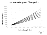
- Figure 1 shows the voltage requirements of a typical submarine system in terms of system voltage as a function of system length and number of fiber pairs.
- various graphs 1, 2, 3, 4, 5 and 6 are shown, each of these graphs correspond to the voltage requirements when the number of fiber pairs used is 1, 2, 3, 4, 5 and 6 respectively.
- the voltage requirements can be as high as about 18kV.
- the voltage requirements for the system are reduced as well. For example, it is readily appreciated that by using 2 fiber pairs, the voltage requirements of the system can be reduced to about 12kV for the same distance of 8000 km.
- a fault occurs such as a power supply failure or a shunt fault in the cable, then a single 12kV power supply is not capable of powering the complete system giving rise to the loss of the traffic in the whole system.
- the present invention proposes the use of a combination of Bridge rectification and forward biasing of Zener diodes usually used in reverse bias mode to reduce the system voltage requirements.
- a system for re-routing power for reducing a voltage requirement in a submarine transmission system comprising at least one power supply for supplying current to a bridge rectifier circuit the latter being adapted to bias a plurality of Zener diodes, each Zener diode being connected in parallel arrangement with a respective optical amplifier, characterized in that said bridge rectifier circuit is adapted for biasing a first predetermined number of Zener diodes in forward bias direction.
- the bridge rectifier circuit is adapted for biasing a second predetermined number of Zener diodes in reverse or powering direction.
- the second predetermined number of Zener diodes comprises two Zener diodes.
- Another object of the present invention is that of providing a method for re-routing power for reducing a voltage requirement in a submarine transmission system, the system comprising at least one power supply for supplying current to a bridge rectifier circuit the latter biasing a plurality of Zener diodes, each Zener diode being connected in parallel arrangement with a respective optical amplifier, characterized in that said bridge rectifier circuit biases a first predetermined number of Zener diodes in forward bias direction.
- the power supply voltage requirements will also drop. For example if at 8000km the 6 fiber pair system can be reduced to a 2 fiber pair system then the power supply requirement can be reduced to below 12kv as represented by graph 2 allowing single end power feeding as the voltage capacity of a conventional power supply is about this level.
- FIG 2 a conventional repeater for supplying power to 6 fiber pairs is shown.
- the line current is represented by I Line with an arrow showing the normal direction of current flow in operating conditions.
- a rectifier bridge 10 is connected to the line current, I Line, at the input and output thereof and connected to 6 Zener diodes 11, 12, 13, 14, 15, 16 at the bridge ports thereof, the Zener diodes being connected in series arrangement.
- Each of the Zener diodes 11, 12, 13, 14, 15, 16 is connected in parallel arrangement to a respective optical amplifier pair 21, 22, 23, 24, 25, 26 which usually comprise a pair of optical fibers.
- the power supply for each amplifier pair is derived from the respective Zener diode connected thereto as it can be seen in figure 2.
- Zener diodes 11 and 12 associated with amplifier pairs 21 and 22 are normally biased as they are inside the bridge rectifier 10. All of the remaining Zener diodes 13, 14, 15, 16 will be forward conducting, hence acting as normal diodes with a low voltage drop.
- the number of optical fiber pairs active in the system has been reduced to 2 pairs 11 and 12, which according to the graphs shown in figure 1 would have reduced voltage requirements in comparison to the 6 fiber pair arrangements. Therefore the two fiber pairs 11 and 12 can be powered with only one power supply and thus the traffic can be restored on the two active optical fiber pairs 11 and 12. It is to be noted that the solution proposed by the present invention requires that the power supply polarity be reversed.
- the bridge can be arranged to encompass any number of fiber pairs according to the conditions and requirement of the system, up to the total number within the repeaters.
Landscapes
- Engineering & Computer Science (AREA)
- Computer Networks & Wireless Communication (AREA)
- Signal Processing (AREA)
- Cable Transmission Systems, Equalization Of Radio And Reduction Of Echo (AREA)
- Optical Communication System (AREA)
- Laying Of Electric Cables Or Lines Outside (AREA)
- Insulated Conductors (AREA)
Abstract
Description
Claims (4)
- System for re-routing power for reducing a voltage requirement in a submarine transmission system, the system comprising at least one power supply for supplying current to a bridge rectifier circuit (10) the latter being adapted to bias a plurality of Zener diodes (11; 12; 13; 14; 15; 16), each Zener diode being connected in parallel arrangement with a respective optical amplifier (21; 22; 23; 24; 25; 26), characterized in that said bridge rectifier circuit (10) is adapted for biasing a first predetermined number of Zener diodes (23; 24; 25; 26) in forward bias direction.
- System according to claim 1, wherein the bridge rectifier circuit (10) is adapted for biasing a second predetermined number of Zener diodes (21; 22) in reverse bias or powering direction.
- System according to claim 2, wherein the second predetermined number of Zener diodes comprises two Zener diodes.
- Method for re-routing power for reducing a voltage requirement in a submarine transmission system, the system comprising at least one power supply for supplying current to a bridge rectifier circuit (10) the latter biasing a plurality of Zener diodes (11; 12; 13; 14; 15; 16), each Zener diode being connected in parallel arrangement with a respective optical amplifier (21; 22; 23; 24; 25; 26), characterized in that said bridge rectifier circuit (10) biases a first predetermined number of Zener diodes (23; 24; 25; 26) in forward bias direction.
Applications Claiming Priority (2)
| Application Number | Priority Date | Filing Date | Title |
|---|---|---|---|
| GB0229980A GB2396499A (en) | 2002-12-21 | 2002-12-21 | Power re-routing system for optical fibre submarine cable |
| GB0229980 | 2002-12-21 |
Publications (3)
| Publication Number | Publication Date |
|---|---|
| EP1437840A2 true EP1437840A2 (en) | 2004-07-14 |
| EP1437840A3 EP1437840A3 (en) | 2004-07-21 |
| EP1437840B1 EP1437840B1 (en) | 2011-09-14 |
Family
ID=9950291
Family Applications (1)
| Application Number | Title | Priority Date | Filing Date |
|---|---|---|---|
| EP03293008A Expired - Lifetime EP1437840B1 (en) | 2002-12-21 | 2003-12-02 | Submarine cable branching unit |
Country Status (5)
| Country | Link |
|---|---|
| US (1) | US7245046B2 (en) |
| EP (1) | EP1437840B1 (en) |
| JP (1) | JP4592279B2 (en) |
| AT (1) | ATE524881T1 (en) |
| GB (1) | GB2396499A (en) |
Families Citing this family (2)
| Publication number | Priority date | Publication date | Assignee | Title |
|---|---|---|---|---|
| EP3926436A4 (en) * | 2019-02-15 | 2022-05-04 | NEC Corporation | Power supply circuit and method for controlling power supply circuit |
| JP7424487B2 (en) | 2020-06-17 | 2024-01-30 | 日本電気株式会社 | Working cable protection monitoring system, working cable protection monitoring method, and working cable protection monitoring program |
Citations (2)
| Publication number | Priority date | Publication date | Assignee | Title |
|---|---|---|---|---|
| JPS60214640A (en) | 1984-04-10 | 1985-10-26 | Fujitsu Ltd | Feeding system for submarine transmission line |
| US5517383A (en) | 1993-03-03 | 1996-05-14 | Stc Submarine Systems Limited | Branching unit for submarine systems |
Family Cites Families (7)
| Publication number | Priority date | Publication date | Assignee | Title |
|---|---|---|---|---|
| GB2280279B (en) * | 1993-07-22 | 1996-06-26 | Northern Telecom Ltd | Branching unit for submarine telecommunications systems |
| JP2571002B2 (en) * | 1993-11-25 | 1997-01-16 | 日本電気株式会社 | Underwater branching device |
| JP3694053B2 (en) * | 1994-03-05 | 2005-09-14 | エステイーシー・サブマリン・システムズ・リミテッド | Branch device for submarine communication system |
| GB9516158D0 (en) * | 1995-08-07 | 1995-10-04 | Stc Submarine Systems Ltd | Switching control circuit for branching units |
| GB9925866D0 (en) * | 1999-11-01 | 1999-12-29 | Cit Alcatel | Branching unit and system for underwater optical communication |
| US6600643B2 (en) * | 2000-12-27 | 2003-07-29 | Pirelli Cavi E Sistemi S.P.A. | Submarine cable branching unit with double-coil relays |
| US7067940B2 (en) * | 2001-12-19 | 2006-06-27 | Pirelli Cavi E Sistemi S.P.A. | Submarine branching unit having asymmetrical architecture |
-
2002
- 2002-12-21 GB GB0229980A patent/GB2396499A/en not_active Withdrawn
-
2003
- 2003-12-02 AT AT03293008T patent/ATE524881T1/en not_active IP Right Cessation
- 2003-12-02 EP EP03293008A patent/EP1437840B1/en not_active Expired - Lifetime
- 2003-12-04 JP JP2003405811A patent/JP4592279B2/en not_active Expired - Lifetime
- 2003-12-18 US US10/737,902 patent/US7245046B2/en not_active Expired - Lifetime
Patent Citations (2)
| Publication number | Priority date | Publication date | Assignee | Title |
|---|---|---|---|---|
| JPS60214640A (en) | 1984-04-10 | 1985-10-26 | Fujitsu Ltd | Feeding system for submarine transmission line |
| US5517383A (en) | 1993-03-03 | 1996-05-14 | Stc Submarine Systems Limited | Branching unit for submarine systems |
Also Published As
| Publication number | Publication date |
|---|---|
| US7245046B2 (en) | 2007-07-17 |
| ATE524881T1 (en) | 2011-09-15 |
| US20040160127A1 (en) | 2004-08-19 |
| EP1437840A3 (en) | 2004-07-21 |
| JP4592279B2 (en) | 2010-12-01 |
| EP1437840B1 (en) | 2011-09-14 |
| GB2396499A (en) | 2004-06-23 |
| JP2004208287A (en) | 2004-07-22 |
| GB0229980D0 (en) | 2003-01-29 |
Similar Documents
| Publication | Publication Date | Title |
|---|---|---|
| US5459328A (en) | Driver circuit for light emitting elements connected in series and an optical amplifying repeater using the same | |
| KR102113452B1 (en) | Subsi Optical Communication Network | |
| US10110321B2 (en) | Techniques for providing adaptive power distribution using a multi-node network of power feed branching units (PFBUs) and an undersea optical communication system using same | |
| KR20130033391A (en) | System and method for transmitting power at the seabed and providing fiber optic communications | |
| US5719693A (en) | Power feeding system for an optical transmission system | |
| CN107534461A (en) | Supply path switching device, supply path switching system and supply path switching method | |
| US5109296A (en) | Transmission line switching system | |
| US7245046B2 (en) | Internal power re-routing by reverse powering to overcome fault scenarios in submarine cable systems | |
| US5532478A (en) | Underwater branching device | |
| JP6825695B2 (en) | Optical submarine cable system and optical submarine relay device | |
| EP3692658B1 (en) | Power delivery in submarine optical communication systems using power feed converters | |
| US7269353B2 (en) | Branching unit for an optical transmission system | |
| EP4572058A1 (en) | Fiber optic cable power in repeatered systems | |
| WO2021124789A1 (en) | Undersea device, energization method, and recording medium | |
| JPS6212217A (en) | Optical communication method | |
| JPS59176936A (en) | Optical repeater | |
| Lilly et al. | Submarine cable systems-recent developments | |
| JPS61273026A (en) | Feeding branch circuit | |
| WO1998001990A2 (en) | Power supply system for telephone line wires | |
| JPH0282675A (en) | Circuit for detecting deterioration of laser diode |
Legal Events
| Date | Code | Title | Description |
|---|---|---|---|
| PUAI | Public reference made under article 153(3) epc to a published international application that has entered the european phase |
Free format text: ORIGINAL CODE: 0009012 |
|
| PUAL | Search report despatched |
Free format text: ORIGINAL CODE: 0009013 |
|
| AK | Designated contracting states |
Kind code of ref document: A2 Designated state(s): AT BE BG CH CY CZ DE DK EE ES FI FR GB GR HU IE IT LI LU MC NL PT RO SE SI SK TR |
|
| AX | Request for extension of the european patent |
Extension state: AL LT LV MK |
|
| AK | Designated contracting states |
Kind code of ref document: A3 Designated state(s): AT BE BG CH CY CZ DE DK EE ES FI FR GB GR HU IE IT LI LU MC NL PT RO SE SI SK TR |
|
| AX | Request for extension of the european patent |
Extension state: AL LT LV MK |
|
| 17P | Request for examination filed |
Effective date: 20041216 |
|
| AKX | Designation fees paid |
Designated state(s): AT BE BG CH CY CZ DE DK EE ES FI FR GB GR HU IE IT LI LU MC NL PT RO SE SI SK TR |
|
| 17Q | First examination report despatched |
Effective date: 20070228 |
|
| RAP1 | Party data changed (applicant data changed or rights of an application transferred) |
Owner name: ALCATEL LUCENT |
|
| GRAC | Information related to communication of intention to grant a patent modified |
Free format text: ORIGINAL CODE: EPIDOSCIGR1 |
|
| GRAP | Despatch of communication of intention to grant a patent |
Free format text: ORIGINAL CODE: EPIDOSNIGR1 |
|
| GRAS | Grant fee paid |
Free format text: ORIGINAL CODE: EPIDOSNIGR3 |
|
| GRAA | (expected) grant |
Free format text: ORIGINAL CODE: 0009210 |
|
| AK | Designated contracting states |
Kind code of ref document: B1 Designated state(s): AT BE BG CH CY CZ DE DK EE ES FI FR GB GR HU IE IT LI LU MC NL PT RO SE SI SK TR |
|
| REG | Reference to a national code |
Ref country code: GB Ref legal event code: FG4D |
|
| REG | Reference to a national code |
Ref country code: CH Ref legal event code: EP |
|
| REG | Reference to a national code |
Ref country code: IE Ref legal event code: FG4D |
|
| REG | Reference to a national code |
Ref country code: DE Ref legal event code: R096 Ref document number: 60338349 Country of ref document: DE Effective date: 20111201 |
|
| REG | Reference to a national code |
Ref country code: NL Ref legal event code: VDEP Effective date: 20110914 |
|
| PG25 | Lapsed in a contracting state [announced via postgrant information from national office to epo] |
Ref country code: SE Free format text: LAPSE BECAUSE OF FAILURE TO SUBMIT A TRANSLATION OF THE DESCRIPTION OR TO PAY THE FEE WITHIN THE PRESCRIBED TIME-LIMIT Effective date: 20110914 Ref country code: FI Free format text: LAPSE BECAUSE OF FAILURE TO SUBMIT A TRANSLATION OF THE DESCRIPTION OR TO PAY THE FEE WITHIN THE PRESCRIBED TIME-LIMIT Effective date: 20110914 |
|
| RAP2 | Party data changed (patent owner data changed or rights of a patent transferred) |
Owner name: ALCATEL LUCENT |
|
| PG25 | Lapsed in a contracting state [announced via postgrant information from national office to epo] |
Ref country code: SI Free format text: LAPSE BECAUSE OF FAILURE TO SUBMIT A TRANSLATION OF THE DESCRIPTION OR TO PAY THE FEE WITHIN THE PRESCRIBED TIME-LIMIT Effective date: 20110914 Ref country code: GR Free format text: LAPSE BECAUSE OF FAILURE TO SUBMIT A TRANSLATION OF THE DESCRIPTION OR TO PAY THE FEE WITHIN THE PRESCRIBED TIME-LIMIT Effective date: 20111215 Ref country code: CY Free format text: LAPSE BECAUSE OF FAILURE TO SUBMIT A TRANSLATION OF THE DESCRIPTION OR TO PAY THE FEE WITHIN THE PRESCRIBED TIME-LIMIT Effective date: 20110914 Ref country code: AT Free format text: LAPSE BECAUSE OF FAILURE TO SUBMIT A TRANSLATION OF THE DESCRIPTION OR TO PAY THE FEE WITHIN THE PRESCRIBED TIME-LIMIT Effective date: 20110914 |
|
| REG | Reference to a national code |
Ref country code: CH Ref legal event code: PCOW Free format text: ALCATEL LUCENT;3, AVENUE OCTAVE GREARD;75007 PARIS (FR) |
|
| REG | Reference to a national code |
Ref country code: AT Ref legal event code: MK05 Ref document number: 524881 Country of ref document: AT Kind code of ref document: T Effective date: 20110914 |
|
| PG25 | Lapsed in a contracting state [announced via postgrant information from national office to epo] |
Ref country code: BE Free format text: LAPSE BECAUSE OF FAILURE TO SUBMIT A TRANSLATION OF THE DESCRIPTION OR TO PAY THE FEE WITHIN THE PRESCRIBED TIME-LIMIT Effective date: 20110914 |
|
| PG25 | Lapsed in a contracting state [announced via postgrant information from national office to epo] |
Ref country code: SK Free format text: LAPSE BECAUSE OF FAILURE TO SUBMIT A TRANSLATION OF THE DESCRIPTION OR TO PAY THE FEE WITHIN THE PRESCRIBED TIME-LIMIT Effective date: 20110914 Ref country code: CZ Free format text: LAPSE BECAUSE OF FAILURE TO SUBMIT A TRANSLATION OF THE DESCRIPTION OR TO PAY THE FEE WITHIN THE PRESCRIBED TIME-LIMIT Effective date: 20110914 |
|
| PG25 | Lapsed in a contracting state [announced via postgrant information from national office to epo] |
Ref country code: EE Free format text: LAPSE BECAUSE OF FAILURE TO SUBMIT A TRANSLATION OF THE DESCRIPTION OR TO PAY THE FEE WITHIN THE PRESCRIBED TIME-LIMIT Effective date: 20110914 Ref country code: IT Free format text: LAPSE BECAUSE OF FAILURE TO SUBMIT A TRANSLATION OF THE DESCRIPTION OR TO PAY THE FEE WITHIN THE PRESCRIBED TIME-LIMIT Effective date: 20110914 Ref country code: RO Free format text: LAPSE BECAUSE OF FAILURE TO SUBMIT A TRANSLATION OF THE DESCRIPTION OR TO PAY THE FEE WITHIN THE PRESCRIBED TIME-LIMIT Effective date: 20110914 Ref country code: PT Free format text: LAPSE BECAUSE OF FAILURE TO SUBMIT A TRANSLATION OF THE DESCRIPTION OR TO PAY THE FEE WITHIN THE PRESCRIBED TIME-LIMIT Effective date: 20120116 Ref country code: NL Free format text: LAPSE BECAUSE OF FAILURE TO SUBMIT A TRANSLATION OF THE DESCRIPTION OR TO PAY THE FEE WITHIN THE PRESCRIBED TIME-LIMIT Effective date: 20110914 |
|
| PLBE | No opposition filed within time limit |
Free format text: ORIGINAL CODE: 0009261 |
|
| STAA | Information on the status of an ep patent application or granted ep patent |
Free format text: STATUS: NO OPPOSITION FILED WITHIN TIME LIMIT |
|
| PG25 | Lapsed in a contracting state [announced via postgrant information from national office to epo] |
Ref country code: MC Free format text: LAPSE BECAUSE OF NON-PAYMENT OF DUE FEES Effective date: 20111231 Ref country code: DK Free format text: LAPSE BECAUSE OF FAILURE TO SUBMIT A TRANSLATION OF THE DESCRIPTION OR TO PAY THE FEE WITHIN THE PRESCRIBED TIME-LIMIT Effective date: 20110914 |
|
| REG | Reference to a national code |
Ref country code: CH Ref legal event code: PL |
|
| 26N | No opposition filed |
Effective date: 20120615 |
|
| REG | Reference to a national code |
Ref country code: IE Ref legal event code: MM4A |
|
| REG | Reference to a national code |
Ref country code: DE Ref legal event code: R097 Ref document number: 60338349 Country of ref document: DE Effective date: 20120615 |
|
| PG25 | Lapsed in a contracting state [announced via postgrant information from national office to epo] |
Ref country code: CH Free format text: LAPSE BECAUSE OF NON-PAYMENT OF DUE FEES Effective date: 20111231 Ref country code: LI Free format text: LAPSE BECAUSE OF NON-PAYMENT OF DUE FEES Effective date: 20111231 Ref country code: IE Free format text: LAPSE BECAUSE OF NON-PAYMENT OF DUE FEES Effective date: 20111202 |
|
| PG25 | Lapsed in a contracting state [announced via postgrant information from national office to epo] |
Ref country code: ES Free format text: LAPSE BECAUSE OF FAILURE TO SUBMIT A TRANSLATION OF THE DESCRIPTION OR TO PAY THE FEE WITHIN THE PRESCRIBED TIME-LIMIT Effective date: 20111225 |
|
| PG25 | Lapsed in a contracting state [announced via postgrant information from national office to epo] |
Ref country code: LU Free format text: LAPSE BECAUSE OF NON-PAYMENT OF DUE FEES Effective date: 20111202 |
|
| PG25 | Lapsed in a contracting state [announced via postgrant information from national office to epo] |
Ref country code: BG Free format text: LAPSE BECAUSE OF FAILURE TO SUBMIT A TRANSLATION OF THE DESCRIPTION OR TO PAY THE FEE WITHIN THE PRESCRIBED TIME-LIMIT Effective date: 20111214 |
|
| PG25 | Lapsed in a contracting state [announced via postgrant information from national office to epo] |
Ref country code: TR Free format text: LAPSE BECAUSE OF FAILURE TO SUBMIT A TRANSLATION OF THE DESCRIPTION OR TO PAY THE FEE WITHIN THE PRESCRIBED TIME-LIMIT Effective date: 20110914 |
|
| PG25 | Lapsed in a contracting state [announced via postgrant information from national office to epo] |
Ref country code: HU Free format text: LAPSE BECAUSE OF FAILURE TO SUBMIT A TRANSLATION OF THE DESCRIPTION OR TO PAY THE FEE WITHIN THE PRESCRIBED TIME-LIMIT Effective date: 20110914 |
|
| REG | Reference to a national code |
Ref country code: FR Ref legal event code: GC Effective date: 20131018 |
|
| REG | Reference to a national code |
Ref country code: FR Ref legal event code: RG Effective date: 20141016 |
|
| REG | Reference to a national code |
Ref country code: FR Ref legal event code: PLFP Year of fee payment: 13 |
|
| REG | Reference to a national code |
Ref country code: FR Ref legal event code: PLFP Year of fee payment: 14 |
|
| REG | Reference to a national code |
Ref country code: FR Ref legal event code: PLFP Year of fee payment: 15 |
|
| PGFP | Annual fee paid to national office [announced via postgrant information from national office to epo] |
Ref country code: GB Payment date: 20221103 Year of fee payment: 20 Ref country code: FR Payment date: 20221110 Year of fee payment: 20 Ref country code: DE Payment date: 20221102 Year of fee payment: 20 |
|
| P01 | Opt-out of the competence of the unified patent court (upc) registered |
Effective date: 20230527 |
|
| REG | Reference to a national code |
Ref country code: DE Ref legal event code: R071 Ref document number: 60338349 Country of ref document: DE |
|
| REG | Reference to a national code |
Ref country code: GB Ref legal event code: PE20 Expiry date: 20231201 |
|
| PG25 | Lapsed in a contracting state [announced via postgrant information from national office to epo] |
Ref country code: GB Free format text: LAPSE BECAUSE OF EXPIRATION OF PROTECTION Effective date: 20231201 |
|
| PG25 | Lapsed in a contracting state [announced via postgrant information from national office to epo] |
Ref country code: GB Free format text: LAPSE BECAUSE OF EXPIRATION OF PROTECTION Effective date: 20231201 |