EP1437797A1 - Antenna coupling device for mobile terminal - Google Patents
Antenna coupling device for mobile terminal Download PDFInfo
- Publication number
- EP1437797A1 EP1437797A1 EP20030029821 EP03029821A EP1437797A1 EP 1437797 A1 EP1437797 A1 EP 1437797A1 EP 20030029821 EP20030029821 EP 20030029821 EP 03029821 A EP03029821 A EP 03029821A EP 1437797 A1 EP1437797 A1 EP 1437797A1
- Authority
- EP
- European Patent Office
- Prior art keywords
- antenna
- coupling member
- antenna coupling
- stopper
- rod
- Prior art date
- Legal status (The legal status is an assumption and is not a legal conclusion. Google has not performed a legal analysis and makes no representation as to the accuracy of the status listed.)
- Granted
Links
Images




Classifications
-
- H—ELECTRICITY
- H04—ELECTRIC COMMUNICATION TECHNIQUE
- H04B—TRANSMISSION
- H04B1/00—Details of transmission systems, not covered by a single one of groups H04B3/00 - H04B13/00; Details of transmission systems not characterised by the medium used for transmission
- H04B1/38—Transceivers, i.e. devices in which transmitter and receiver form a structural unit and in which at least one part is used for functions of transmitting and receiving
-
- H—ELECTRICITY
- H01—ELECTRIC ELEMENTS
- H01Q—ANTENNAS, i.e. RADIO AERIALS
- H01Q1/00—Details of, or arrangements associated with, antennas
- H01Q1/08—Means for collapsing antennas or parts thereof
- H01Q1/088—Quick-releasable antenna elements
-
- H—ELECTRICITY
- H01—ELECTRIC ELEMENTS
- H01Q—ANTENNAS, i.e. RADIO AERIALS
- H01Q1/00—Details of, or arrangements associated with, antennas
- H01Q1/12—Supports; Mounting means
- H01Q1/22—Supports; Mounting means by structural association with other equipment or articles
- H01Q1/24—Supports; Mounting means by structural association with other equipment or articles with receiving set
- H01Q1/241—Supports; Mounting means by structural association with other equipment or articles with receiving set used in mobile communications, e.g. GSM
- H01Q1/242—Supports; Mounting means by structural association with other equipment or articles with receiving set used in mobile communications, e.g. GSM specially adapted for hand-held use
- H01Q1/243—Supports; Mounting means by structural association with other equipment or articles with receiving set used in mobile communications, e.g. GSM specially adapted for hand-held use with built-in antennas
- H01Q1/244—Supports; Mounting means by structural association with other equipment or articles with receiving set used in mobile communications, e.g. GSM specially adapted for hand-held use with built-in antennas extendable from a housing along a given path
Definitions
- the present invention relates to an antenna coupling device for a mobile terminal, and more particularly to an antenna coupling device for a mobile terminal which is configured to selectively restrain an antenna coupling member fitted in an antenna housing to rotate the antenna coupling member by rotation of an antenna of the mobile terminal.
- a “mobile communication terminal” is a device adapted to allow the user to conduct wireless communication with a counterpart.
- a mobile communication terminal includes a hand held phone (HHP), a cordless telephone 2 (CT-2), a cellular phone, a digital phone, a personal communication system (PCS) phone, a personal digital assistant (PDA), etc.
- HHP hand held phone
- CT-2 cordless telephone 2
- PCS personal communication system
- PDA personal digital assistant
- These mobile wireless terminals are classified into a bar type, a flip type, and a folder type in terms of their outer structures.
- Such conventional mobile terminals are essentially equipped with an antenna unit, a data input/output unit, and a data transmitting/receiving unit.
- a liquid crystal display LCD
- a key pad or touch screen is commonly used.
- the keypad used to input data has an arrangement of a plurality of keys including a conversation start button, that is, a send (SND) key, a cancel key, a correction or clear (CLR) key, numeral keys, character keys, an end (END) key, function keys, a power (PWR) key, etc.
- a conversation start button that is, a send (SND) key, a cancel key, a correction or clear (CLR) key, numeral keys, character keys, an end (END) key, function keys, a power (PWR) key, etc.
- the antenna unit is mounted to a desired portion of a terminal body in the mobile terminal in order to receive a signal transmitted to the terminal.
- a retractable antenna is mainly used which is a combination of a whip antenna and a helical antenna.
- An example of such a retractable antenna is illustrated in Fig. 1.
- the retractable antenna includes a whip antenna 4 having a dummy rod 4a, a rod antenna 4b, and an antenna stopper 4c, and a helical antenna 5 having an antenna housing 5a internally provided with helical coils, and an antenna coupling member 5b coupled to an antenna bushing 2a fixed to a lower case frame 2 included in a terminal body 1 of a mobile terminal.
- the rod antenna 4b extends through the antenna housing 5a and antenna coupling member 5b such that it is extendable from and retractable into the terminal body 1.
- the first type antenna coupling device is used.
- the configuration of this first type antenna coupling device is shown in Fig. 2.
- the antenna coupling member 5b is formed at the antenna housing 5a such that it is integral with the antenna housing 5a, as shown in Fig. 2.
- the antenna coupling member 5b is adapted to be threadedly coupled with the antenna bushing 2a fixed to the lower case frame 2.
- the antenna has a circular cross-section, as shown in Fig. 3.
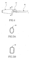
- the second type antenna coupling device is illustrated in Fig. 4.
- a hook-shaped coupling member 51 is formed at an antenna housing 50 such that it is integral with the antenna housing 50, as shown in Fig. 4.
- the hook-shaped coupling member 51 is adapted to be engaged, in a hooking fashion, with a rib (not shown) formed at the lower case frame 2.
- the antenna may have an oval or rectangular cross-section, as shown in Fig. 5a or 5b.
- the antenna housing having a circular cross-section can be reliably coupled with the antenna bushing in accordance with its rotation during assembly.
- the antenna housing has an oval or rectangular cross-section a problem arises because it is necessary to use the second type antenna coupling device using the hooking method.
- the rib may be easily damaged, or the hook coupling member may be inaccurately engaged with the rib.
- An aspect of the invention is to provide an antenna coupling device for a mobile terminal which includes an antenna coupling member separate from the antenna housing of an antenna unit, enabling disassembly of the antenna housing and antenna coupling member when the antenna unit is damaged, so that only the damaged element of the antenna unit can be replaced with a new one, thereby reducing maintenance costs.
- Another aspect of the invention is to provide an antenna coupling device for a mobile terminal which includes an annular reinforcing member adapted to reinforce the coupling between the antenna housing of an antenna unit and an antenna coupling member, thereby enhancing the coupling force of the antenna unit, so that it is possible to prevent deformation of the antenna unit during use while avoiding formation of a clearance space at a terminal body of the mobile terminal.
- an antenna coupling device for a mobile terminal adapted to couple, to a terminal body of the mobile terminal, an antenna unit including an antenna housing adapted to be coupled to the terminal body, and an antenna extending through the antenna housing into the terminal body at an inner end thereof, comprising: an antenna coupling member rotatably fitted in the antenna housing at one end of the antenna housing facing the terminal body; and restraining means for selectively engaging the antenna with the antenna coupling member to restrain the antenna coupling member by the antenna, thereby causing the antenna coupling member to be coupled to an antenna bushing provided at the terminal body by rotation of the antenna.
- an antenna unit for a mobile terminal which includes an antenna coupling device according to an embodiment of the present invention.
- the antenna unit includes an antenna housing 100 internally provided with a helical antenna 1000 consisting of helical coils, an antenna 200, a hollow antenna coupling member 400, and restraining means 500.
- the antenna coupling member 400 is arranged at a lower end of the antenna housing 100 such that it is rotatable for coupling to a terminal body.
- the antenna coupling member 400 is separate from the antenna housing 100.
- the restraining means 500 serves to selectively engage the antenna 200 with the antenna coupling member 400, thereby allowing the antenna coupling member 400 to be rotated along with rotation of the antenna 200.
- the restraining means 500 comprises an engaging element provided at a portion of the antenna 200 positioned near an antenna stopper 201 formed at an inner end of the antenna 200 received in the terminal body 1, and another engaging element provided at one end of the antenna coupling member 400 fitted in the antenna housing 100.
- the antenna coupling member 400 protrudes from the antenna housing 100 at the other end thereof.
- the antenna coupling member 400 is provided at the other end thereof with threads so that it can be threadedly coupled with an antenna bushing 2a fixed to a lower case frame 2 of the mobile terminal.
- the antenna coupling member 400 is preferably made of a metal material, taking into consideration the frequency characteristics of the antenna unit.
- An annular reinforcing member 300 is interposed between the antenna housing 100 and the antenna coupling member 400.
- a stopper 401 radially protrudes from the outer circumferential surface of the antenna coupling member 400 near one end of the antenna coupling member 400, so as to prevent the antenna coupling member 400 from being separated from the annular reinforcing member 300, and thus, the antenna housing 100.
- the antenna coupling member 400 is rotatable within the annular reinforcing member 300.
- the annular reinforcing member 300 is also preferably made of a metal material, taking into consideration the frequency characteristics of the antenna unit.
- the antenna coupling member 400 is coupled with the annular reinforcing member 300 and then, the stopper 201 which is the ending portion of the antenna 200 is forcibly pushed or inserted to the antenna coupling member 400 to be thereby coupled with the antenna 200 by punching operation.
- the restraining means 500 comprises, for the engaging elements thereof, a rod-shaped stopper 501 provided at a portion of the antenna 200 positioned near the antenna stopper 201 and preferably has a polygonal cross-section.
- the restraining means 500 further comprises a stopper bore 502 formed at one end of the antenna coupling member 400, which also preferably has a polygonal cross-section corresponding to that of the rod-shaped stopper 501.
- the stopper bore 502 preferably has a regular hexagonal shape.
- the rod-shaped stopper 501 has a size such that its diameter of its circumscribed circle is larger than the diameter of the antenna 200.
- the antenna coupling member 400 has a circular bore 800 extending axially from the stopper bore 502 through the antenna coupling member 400. The circular bore 800 serves to receive the rod-shaped stopper 501 separated from the stopper bore 502 when the antenna 200 is retracted into the terminal body 1.
- the circular bore 800 has a diameter larger than the diameter of the circumscribed circle of the rod-shaped stopper 501 so as to prevent the antenna coupling member 400 from being restrained by the antenna 200.
- a guide tube 600 (Fig. 10) is connected to the circular bore 800 in order to guide a sliding movement of the antenna 200 therethrough.
- the restraining means 500 comprises a rod-shaped stopper 501' extending from the inner end of the antenna 200 received in the terminal body.
- the rod-shaped stopper 501' is provided at a circumferential surface thereof with a plurality of first protrusions 501a extending longitudinally along the rod-shaped stopper 501', and a plurality of first grooves 501b each extending longitudinally along the rod-shaped stopper 501' while being arranged between adjacent ones of the first protrusions 501a.
- the rod-shaped stopper 501' may have one first protrusion 501a, and one first groove 501b.
- the restraining means 500 also comprises a stopper bore 502' formed at one end of the antenna coupling member 400, and adapted to engage with the rod-shaped stopper 501'.
- the stopper bore 502' is provided at a circumferential surface thereof with a plurality of second protrusions 502a extending longitudinally along the stopper bore 502', and a plurality of second grooves 502b each extending longitudinally along the stopper bore 502' while being arranged between adjacent ones of the second protrusions 502a.
- the stopper bore 502' may have one second protrusion 502a, and one second groove 502b.
- the first protrusions and grooves 501a and 501b are engagable with the second grooves and protrusions 502b and 502a, respectively.
- the rod-shaped stopper 501' has a star shape.
- the protrusions and grooves 502a and 502b of the stopper bore 502' are symmetrically arranged.
- the rod-shaped stopper 501' faces the helical antenna 100.
- the rod-shaped stopper 501' has a size such that the diameter of its circumscribed circle is larger than the diameter of the antenna 200.
- the antenna coupling member 400 has a circular bore 800 extending axially from the stopper bore 502' through the antenna coupling member 400.
- the circular bore 800 serves to receive the rod-shaped stopper 501' separated from the stopper bore 502' when the antenna 200 is retracted into the terminal body 1.
- the circular bore 800 has a diameter larger than the diameter of the circumscribed circle of the rod-shaped stopper 501' so as to prevent the antenna coupling member 400 from being restrained by the antenna 200.
- a guide tube 600 is connected to the circular bore 800 in order to guide a sliding movement of the antenna 200 therethrough.
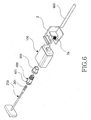
- the antenna coupling member 400 is first mounted to the lower end of the antenna housing 100, as shown in Figs. 6 and 9.
- the annular reinforcing member 300 adapted to reinforce the coupling force of the antenna coupling member 400 is interposed between the antenna housing 100 and the antenna coupling member 400. That is, the antenna coupling member 400 is fitted in the annular reinforcing member 300 such that it is simultaneously rotatable.
- the antenna 200 is inserted into the antenna coupling member 400 such that it extends through the antenna housing 100.
- the restraining means 500 can operate to engage the antenna 200 with the antenna coupling member 400. That is, when the antenna 200 completely protrudes from the antenna housing 100, the rod-shaped stopper 501, which extends from the inner end of the antenna 200 to a desired length while having a polygonal cross-section, as shown in Figs. 13 and 14, is engaged with the polygonal stopper bore 502 formed at one end of the antenna coupling member 400. Accordingly, the antenna coupling member 400 is restrained by the antenna 200.
- the antenna coupling member 400 When the antenna 200 rotates in this state, the antenna coupling member 400 is rotated, as shown in Figs. 10 and 11. At this time, the antenna housing 100 is maintained at a fixed state. Since the antenna coupling member 400 is provided with threads at the other end thereof protruded from the annular reinforcing member 300, it can be threadedly coupled with the antenna bushing 2a by the threads in accordance with the rotation of the antenna coupling member 400.
- the rod-shaped stopper 501 When the antenna 200 is retracted through the antenna housing 100 into the terminal body 1 in the state in which the antenna coupling member 400 is threadedly coupled with the antenna bushing 2a, the rod-shaped stopper 501 is separated from the stopper bore 502, as shown in Fig. 12. The rod-shaped stopper 501 is then introduced into the circular bore 800 having a diameter larger than the diameter of the circumscribed circle of the rod-shaped stopper 501, as shown in Fig. 19. Accordingly, the antenna can be freely rotated, and the restraint of the antenna coupling member 400 by the antenna is released. Thus, the coupling of the antenna unit to the terminal body is completed.
- the restraining means 500 comprises the rod-shaped stopper 501' extending from the inner end of the antenna 200 while being provided at a circumferential surface thereof with the first protrusions and grooves 501a and 501b extending longitudinally along the rod-shaped stopper 501', and the stopper bore 502' formed at one end of the antenna coupling member 400 while being provided at a circumferential surface thereof with the second protrusions and grooves 502a and 502b extending longitudinally along the stopper bore 502'.
- the antenna coupling member 400 is restrained by the antenna 200.
- the antenna coupling member 400 is rotated.
- the antenna housing 100 is maintained at a fixed state. Accordingly, the antenna coupling member 400 can be threadedly coupled with the antenna bushing 2a by the threads formed at the other. end of the antenna coupling member 400, in accordance with the rotation of the antenna coupling member 400.
- the first protrusions and grooves 501a and 501b of the rod-shaped stopper 501' are disengaged from the second grooves and protrusions 502b and 502a of the stopper bore 502', respectively.
- the rod-shaped stopper 501 is then introduced into the circular bore 800 having a diameter larger than the diameter of the circumscribed circle of the rod-shaped stopper 501, as shown in Fig. 19. Accordingly, the antenna can be freely rotated, and the restraint of the antenna coupling member 400 by the antenna is released. Thus, the coupling of the antenna unit to the terminal body is completed.
- the antenna coupling member is restrained by the antenna in accordance with the configuration of the restraining means. Accordingly, it is possible to easily couple the antenna unit to the terminal body while achieving an enhancement in coupling force.
Landscapes
- Engineering & Computer Science (AREA)
- Computer Networks & Wireless Communication (AREA)
- Signal Processing (AREA)
- Support Of Aerials (AREA)
- Telephone Set Structure (AREA)
- Details Of Aerials (AREA)
Abstract
Description
- The present invention relates to an antenna coupling device for a mobile terminal, and more particularly to an antenna coupling device for a mobile terminal which is configured to selectively restrain an antenna coupling member fitted in an antenna housing to rotate the antenna coupling member by rotation of an antenna of the mobile terminal.
- Generally, a "mobile communication terminal" is a device adapted to allow the user to conduct wireless communication with a counterpart. Such a mobile communication terminal includes a hand held phone (HHP), a cordless telephone 2 (CT-2), a cellular phone, a digital phone, a personal communication system (PCS) phone, a personal digital assistant (PDA), etc. These mobile wireless terminals are classified into a bar type, a flip type, and a folder type in terms of their outer structures. Such conventional mobile terminals are essentially equipped with an antenna unit, a data input/output unit, and a data transmitting/receiving unit. For the data input/output unit, a liquid crystal display (LCD) is commonly used. For the data input/output unit, a key pad or touch screen is commonly used. Basically, the keypad used to input data has an arrangement of a plurality of keys including a conversation start button, that is, a send (SND) key, a cancel key, a correction or clear (CLR) key, numeral keys, character keys, an end (END) key, function keys, a power (PWR) key, etc.
- The antenna unit is mounted to a desired portion of a terminal body in the mobile terminal in order to receive a signal transmitted to the terminal. For such an antenna unit, a retractable antenna is mainly used which is a combination of a whip antenna and a helical antenna. An example of such a retractable antenna is illustrated in Fig. 1. As shown in Fig. 1, the retractable antenna includes a
whip antenna 4 having adummy rod 4a, arod antenna 4b, and anantenna stopper 4c, and ahelical antenna 5 having anantenna housing 5a internally provided with helical coils, and anantenna coupling member 5b coupled to anantenna bushing 2a fixed to alower case frame 2 included in a terminal body 1 of a mobile terminal. Therod antenna 4b extends through theantenna housing 5a andantenna coupling member 5b such that it is extendable from and retractable into the terminal body 1. - Typically, there are two types of antenna coupling devices. In the case illustrated in Fig. 1, the first type antenna coupling device is used. The configuration of this first type antenna coupling device is shown in Fig. 2. In the first type antenna coupling device, the
antenna coupling member 5b is formed at theantenna housing 5a such that it is integral with theantenna housing 5a, as shown in Fig. 2. Theantenna coupling member 5b is adapted to be threadedly coupled with the antenna bushing 2a fixed to thelower case frame 2. In this case, the antenna has a circular cross-section, as shown in Fig. 3. The second type antenna coupling device is illustrated in Fig. 4. In this second type antenna coupling device, a hook-shaped coupling member 51 is formed at anantenna housing 50 such that it is integral with theantenna housing 50, as shown in Fig. 4. The hook-shaped coupling member 51 is adapted to be engaged, in a hooking fashion, with a rib (not shown) formed at thelower case frame 2. In this case, the antenna may have an oval or rectangular cross-section, as shown in Fig. 5a or 5b. - Where the first type antenna coupling device is used, the antenna housing having a circular cross-section can be reliably coupled with the antenna bushing in accordance with its rotation during assembly. However, where the antenna housing has an oval or rectangular cross-section a problem arises because it is necessary to use the second type antenna coupling device using the hooking method. Among the problems that arise, the rib may be easily damaged, or the hook coupling member may be inaccurately engaged with the rib. As a result, there may be a clearance space at the antenna housing, resulting in a loose antenna.
- It is the object of the invention to provide an antenna coupling device for a mobile terminal which is configured to selectively restrain an antenna coupling member fitted in an antenna housing to rotate the antenna coupling member by rotation of an antenna of the mobile terminal, thereby being capable of easily coupling antenna units which may have diverse shapes.
- This object is solved by the subject matters of the independent claims.
- Preferred embodiments are defined by the dependent claims.
- An aspect of the invention is to provide an antenna coupling device for a mobile terminal which includes an antenna coupling member separate from the antenna housing of an antenna unit, enabling disassembly of the antenna housing and antenna coupling member when the antenna unit is damaged, so that only the damaged element of the antenna unit can be replaced with a new one, thereby reducing maintenance costs.
- Another aspect of the invention is to provide an antenna coupling device for a mobile terminal which includes an annular reinforcing member adapted to reinforce the coupling between the antenna housing of an antenna unit and an antenna coupling member, thereby enhancing the coupling force of the antenna unit, so that it is possible to prevent deformation of the antenna unit during use while avoiding formation of a clearance space at a terminal body of the mobile terminal.
- In accordance with the present invention, there is provided an antenna coupling device for a mobile terminal adapted to couple, to a terminal body of the mobile terminal, an antenna unit including an antenna housing adapted to be coupled to the terminal body, and an antenna extending through the antenna housing into the terminal body at an inner end thereof, comprising: an antenna coupling member rotatably fitted in the antenna housing at one end of the antenna housing facing the terminal body; and restraining means for selectively engaging the antenna with the antenna coupling member to restrain the antenna coupling member by the antenna, thereby causing the antenna coupling member to be coupled to an antenna bushing provided at the terminal body by rotation of the antenna.
- The above advantages of the present invention will become more apparent by describing in detail preferred embodiments thereof with reference to the attached drawings in which:
- Fig. 1 is a sectional view illustrating an example of a conventional antenna coupling device for a mobile terminal;
- Fig. 2 is a perspective view illustrating the conventional antenna coupling device;
- Fig. 3 is a cross-sectional view taken along the line A - A' of Fig. 2;
- Fig. 4 is a perspective view illustrating another example of a conventional antenna coupling device for a mobile terminal;
- Fig. 5a is a cross-sectional view taken along the line B - B' of Fig. 4;
- Fig. 5b is a cross-sectional view similar to Fig. 5a, illustrating another antenna housing;
- Fig. 6 is an exploded perspective view illustrating the configuration of an antenna coupling device for a mobile terminal in accordance with a first embodiment of the present invention;
- Fig. 7 is a sectional view illustrating a part of the antenna coupling device according to the first embodiment of the present invention in which an antenna coupling member included in the antenna coupling device is fitted in an antenna housing;
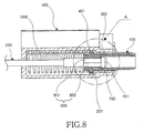
- Fig. 8 is a sectional view illustrating a part of the antenna coupling device according to the first embodiment of the present invention in which a rod-shaped antenna is engaged with the antenna coupling member included in the antenna coupling device to restrain the antenna coupling member;
- Fig. 9 is an enlarged view corresponding to a portion "A" of Fig. 8;
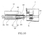
- Fig. 10 is a partially-broken perspective view illustrating the antenna coupling device according to the first embodiment of the present invention before it is coupled to an antenna bushing;
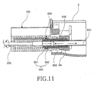
- Fig. 11 is a partially-broken perspective view illustrating the antenna coupling device according to the first embodiment of the present invention after it is coupled to the antenna bushing with the rod antenna extended;
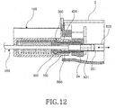
- Fig. 12 is a partially-broken perspective view illustrating the antenna coupling device of Fig. 11 with the rod antenna partially retreated;
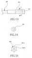
- Fig. 13 is a side view illustrating a rod-shaped stopper included in the antenna coupling device according to the first embodiment of the present invention;
- Fig. 14 is a cross-sectional view taken along the line C - C' of Fig. 13;
- Fig. 15 is a cross-sectional view illustrating a second embodiment of the rod-shaped stopper;
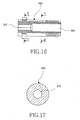
- Fig. 16 is a sectional view illustrating the antenna coupling member included in the antenna coupling device according to the first embodiment of the present invention;
- Fig. 17 is a cross-sectional view taken along the line D - D' of Fig. 16;
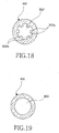
- Fig. 18 is a sectional view illustrating the antenna coupling member included in the antenna coupling device according to the second embodiment of the present invention; and
- Fig. 19 is a cross-sectional view taken along the line E - E' of Fig. 16.
-
- Now, preferred embodiments of the present invention will be described in detail with reference to the annexed drawings.
- Referring to Figs. 6 to 14, 16, 17, and 19, an antenna unit for a mobile terminal is illustrated which includes an antenna coupling device according to an embodiment of the present invention. The antenna unit includes an
antenna housing 100 internally provided with ahelical antenna 1000 consisting of helical coils, anantenna 200, a hollowantenna coupling member 400, and restraining means 500. Theantenna coupling member 400 is arranged at a lower end of the antenna housing 100 such that it is rotatable for coupling to a terminal body. Theantenna coupling member 400 is separate from theantenna housing 100. The restraining means 500 serves to selectively engage theantenna 200 with theantenna coupling member 400, thereby allowing theantenna coupling member 400 to be rotated along with rotation of theantenna 200. The restraining means 500 comprises an engaging element provided at a portion of theantenna 200 positioned near anantenna stopper 201 formed at an inner end of theantenna 200 received in the terminal body 1, and another engaging element provided at one end of theantenna coupling member 400 fitted in theantenna housing 100. Theantenna coupling member 400 protrudes from theantenna housing 100 at the other end thereof. Theantenna coupling member 400 is provided at the other end thereof with threads so that it can be threadedly coupled with anantenna bushing 2a fixed to alower case frame 2 of the mobile terminal. Theantenna coupling member 400 is preferably made of a metal material, taking into consideration the frequency characteristics of the antenna unit. - An annular reinforcing
member 300 is interposed between theantenna housing 100 and theantenna coupling member 400. Astopper 401 radially protrudes from the outer circumferential surface of theantenna coupling member 400 near one end of theantenna coupling member 400, so as to prevent theantenna coupling member 400 from being separated from the annular reinforcingmember 300, and thus, theantenna housing 100. Theantenna coupling member 400 is rotatable within the annular reinforcingmember 300. The annular reinforcingmember 300 is also preferably made of a metal material, taking into consideration the frequency characteristics of the antenna unit. - Herein, the
antenna coupling member 400 is coupled with the annular reinforcingmember 300 and then, thestopper 201 which is the ending portion of theantenna 200 is forcibly pushed or inserted to theantenna coupling member 400 to be thereby coupled with theantenna 200 by punching operation. - The restraining means 500 comprises, for the engaging elements thereof, a rod-shaped
stopper 501 provided at a portion of theantenna 200 positioned near theantenna stopper 201 and preferably has a polygonal cross-section. The restraining means 500 further comprises astopper bore 502 formed at one end of theantenna coupling member 400, which also preferably has a polygonal cross-section corresponding to that of the rod-shapedstopper 501. When it is desired to threadedly couple theantenna coupling member 400 with theantenna bushing 2a, the rod-shapedstopper 501 is engaged with the stopper bore 502 so that theantenna coupling member 400 can be rotated along with rotation of theantenna 200. An inclined guide surface 700 (see Fig. 9) is formed at one end of the stopper bore 502 facing theantenna stopper 201. Theinclined guide surface 700 comes into contact with an end of the rod-shapedstopper 501 opposite to theantenna stopper 201, thereby guiding the rod-shapedstopper 501 into the stopper bore 502. The stopper bore 502 preferably has a regular hexagonal shape. The rod-shapedstopper 501 has a size such that its diameter of its circumscribed circle is larger than the diameter of theantenna 200. Theantenna coupling member 400 has acircular bore 800 extending axially from the stopper bore 502 through theantenna coupling member 400. Thecircular bore 800 serves to receive the rod-shapedstopper 501 separated from the stopper bore 502 when theantenna 200 is retracted into the terminal body 1. Thecircular bore 800 has a diameter larger than the diameter of the circumscribed circle of the rod-shapedstopper 501 so as to prevent theantenna coupling member 400 from being restrained by theantenna 200. A guide tube 600 (Fig. 10) is connected to thecircular bore 800 in order to guide a sliding movement of theantenna 200 therethrough. - Now, another embodiment of the present invention associated with the restraining means will be described with respect to Figs. 15 and 18.
- In accordance with this embodiment, the restraining means 500 comprises a rod-shaped stopper 501' extending from the inner end of the
antenna 200 received in the terminal body. As shown in Fig. 15, the rod-shaped stopper 501' is provided at a circumferential surface thereof with a plurality offirst protrusions 501a extending longitudinally along the rod-shaped stopper 501', and a plurality offirst grooves 501b each extending longitudinally along the rod-shaped stopper 501' while being arranged between adjacent ones of thefirst protrusions 501a. Although not shown, the rod-shaped stopper 501' may have onefirst protrusion 501a, and onefirst groove 501b. In accordance with this embodiment, the restraining means 500 also comprises a stopper bore 502' formed at one end of theantenna coupling member 400, and adapted to engage with the rod-shaped stopper 501'. As shown in Fig. 18, the stopper bore 502' is provided at a circumferential surface thereof with a plurality ofsecond protrusions 502a extending longitudinally along the stopper bore 502', and a plurality ofsecond grooves 502b each extending longitudinally along the stopper bore 502' while being arranged between adjacent ones of thesecond protrusions 502a. Although not shown, the stopper bore 502' may have onesecond protrusion 502a, and onesecond groove 502b. The first protrusions andgrooves protrusions grooves antenna 200 completely protrudes from theantenna housing 100, the rod-shaped stopper 501' faces thehelical antenna 100. The rod-shaped stopper 501' has a size such that the diameter of its circumscribed circle is larger than the diameter of theantenna 200. Similarly to the previously-described embodiment, theantenna coupling member 400 has acircular bore 800 extending axially from the stopper bore 502' through theantenna coupling member 400. Thecircular bore 800 serves to receive the rod-shaped stopper 501' separated from the stopper bore 502' when theantenna 200 is retracted into the terminal body 1. Thecircular bore 800 has a diameter larger than the diameter of the circumscribed circle of the rod-shaped stopper 501' so as to prevent theantenna coupling member 400 from being restrained by theantenna 200. Aguide tube 600 is connected to thecircular bore 800 in order to guide a sliding movement of theantenna 200 therethrough. - Now, the assembling procedure and operation of the antenna coupling device having the above described configuration according to the first embodiment (Figs. 6-14) of the present invention will be described in detail with reference to the annexed drawings.
- In order to mount the
antenna housing 100 to thelower case frame 2 of the terminal body 1 in the mobile terminal, theantenna coupling member 400 is first mounted to the lower end of theantenna housing 100, as shown in Figs. 6 and 9. At this time, the annular reinforcingmember 300 adapted to reinforce the coupling force of theantenna coupling member 400 is interposed between theantenna housing 100 and theantenna coupling member 400. That is, theantenna coupling member 400 is fitted in the annular reinforcingmember 300 such that it is simultaneously rotatable. Thereafter, theantenna 200 is inserted into theantenna coupling member 400 such that it extends through theantenna housing 100. - When it is desired to threadedly couple the
antenna coupling member 400 with theantenna bushing 2a, theantenna 200 completely protrudes from theantenna housing 100. In this state, the restraining means 500 can operate to engage theantenna 200 with theantenna coupling member 400. That is, when theantenna 200 completely protrudes from theantenna housing 100, the rod-shapedstopper 501, which extends from the inner end of theantenna 200 to a desired length while having a polygonal cross-section, as shown in Figs. 13 and 14, is engaged with the polygonal stopper bore 502 formed at one end of theantenna coupling member 400. Accordingly, theantenna coupling member 400 is restrained by theantenna 200. When theantenna 200 rotates in this state, theantenna coupling member 400 is rotated, as shown in Figs. 10 and 11. At this time, theantenna housing 100 is maintained at a fixed state. Since theantenna coupling member 400 is provided with threads at the other end thereof protruded from the annular reinforcingmember 300, it can be threadedly coupled with theantenna bushing 2a by the threads in accordance with the rotation of theantenna coupling member 400. - When the
antenna 200 is retracted through theantenna housing 100 into the terminal body 1 in the state in which theantenna coupling member 400 is threadedly coupled with theantenna bushing 2a, the rod-shapedstopper 501 is separated from the stopper bore 502, as shown in Fig. 12. The rod-shapedstopper 501 is then introduced into thecircular bore 800 having a diameter larger than the diameter of the circumscribed circle of the rod-shapedstopper 501, as shown in Fig. 19. Accordingly, the antenna can be freely rotated, and the restraint of theantenna coupling member 400 by the antenna is released. Thus, the coupling of the antenna unit to the terminal body is completed. - The assembling procedure and operation of the antenna coupling device having the above described configuration according to the second embodiment of the present invention will be described.
- As shown in Figs. 15 and 18, the restraining means 500 according to this embodiment comprises the rod-shaped stopper 501' extending from the inner end of the
antenna 200 while being provided at a circumferential surface thereof with the first protrusions andgrooves antenna coupling member 400 while being provided at a circumferential surface thereof with the second protrusions andgrooves - Accordingly, when the
antenna 200 completely protrudes from theantenna housing 100, the first protrusions andgrooves protrusions antenna coupling member 400 is restrained by theantenna 200. When theantenna 200 rotates in this state, theantenna coupling member 400 is rotated. At this time, theantenna housing 100 is maintained at a fixed state. Accordingly, theantenna coupling member 400 can be threadedly coupled with theantenna bushing 2a by the threads formed at the other. end of theantenna coupling member 400, in accordance with the rotation of theantenna coupling member 400. - When the
antenna 200 is retracted through theantenna housing 100 into the terminal body 1 in the state in which theantenna coupling member 400 is threadedly coupled with theantenna bushing 2a, the first protrusions andgrooves protrusions stopper 501 is then introduced into thecircular bore 800 having a diameter larger than the diameter of the circumscribed circle of the rod-shapedstopper 501, as shown in Fig. 19. Accordingly, the antenna can be freely rotated, and the restraint of theantenna coupling member 400 by the antenna is released. Thus, the coupling of the antenna unit to the terminal body is completed. - As apparent from the above description, the antenna coupling member is restrained by the antenna in accordance with the configuration of the restraining means. Accordingly, it is possible to easily couple the antenna unit to the terminal body while achieving an enhancement in coupling force.
- While the present invention has been described in connection with what is presently considered to be the most practical and preferred embodiment, it is to be understood that the invention is not limited to the disclosed embodiments, but, on the contrary, it is intended to cover various modifications within the scope of the appended claims.
Claims (16)
- An antenna coupling device for coupling an antenna unit to a terminal body of a mobile terminal, the antenna unit including an antenna housing adapted to be coupled to the terminal body, and an antenna extending through the antenna housing into the terminal body at an inner end thereof, comprising:an antenna coupling member rotatably fitted in the antenna housing at one end of the antenna housing facing the terminal body; andrestraining means for selectively engaging the antenna with the antenna coupling member to restrain the antenna coupling member by the antenna, thereby causing the antenna coupling member to be coupled to an antenna bushing provided at the terminal body in accordance with rotation of the antenna.
- The antenna coupling device according to claim 1, wherein the antenna coupling member is fitted, at one end thereof, in the antenna housing while having, at the other end thereof, threads to be threadedly coupled to the antenna bushing.
- The antenna coupling device according to claim 1 or 2, wherein the antenna coupling member is made of a metal material.
- The antenna coupling device according to one of claims 1 to 3, wherein the antenna coupling member has a stopper radially protruding from. an outer circumferential surface of the antenna coupling member near one end of the antenna coupling member fitted in the antenna housing, and adapted to prevent the antenna coupling member from being separated from the antenna housing.
- The antenna coupling device according to one of claims 1 to 4, further comprising:an annular reinforcing member interposed between the antenna housing and the antenna coupling member, and adapted to reinforce a coupling force of the antenna coupling member.
- The antenna coupling device according to claim 5, wherein the annular reinforcing member is made of a metal material.
- The antenna coupling device according to one of claims 1 to 6, wherein the restraining means comprises:a rod-shaped stopper provided at a portion of the antenna positioned near an antenna stopper formed at the inner end of the antenna, the rod-shaped stopper having a predetermined length and a polygonal cross-section; anda stopper bore formed at one end of the antenna coupling member and having a polygonal cross-section corresponding to that of the rod-shaped stopper, and adapted to be engagable with the rod-shaped stopper, whereby the antenna and the antenna coupling member can rotate simultaneously.
- The antenna coupling device according to claim 7, wherein the antenna coupling member is formed with an inclined guide surface at one end of the stopper bore positioned toward the other end of the antenna coupling member, the inclined guide surface being adapted to come into contact with an end of the rod-shaped stopper opposite to the other end of the antenna coupling member, thereby guiding the rod-shaped stopper into the stopper hole.
- The antenna coupling device according to claim 7 or 8, wherein the polygonal cross-section is a regular hexagonal cross-section.
- The antenna coupling device according to one of claims 1 to 9, wherein the restraining means comprises:a rod-shaped stopper provided at a portion of the antenna positioned near an antenna stopper formed at the inner end of the antenna, the rod-shaped stopper having a predetermined length and being provided at a circumferential surface thereof with a plurality of first protrusions extending longitudinally along the rod-shaped stopper, and a plurality of first grooves each arranged between adjacent ones of the first protrusions; anda stopper bore formed at one end of the antenna coupling member, the stopper bore being provided at a circumferential surface thereof with a plurality of second protrusions extending longitudinally along the stopper bore, and a plurality of second grooves each arranged between adjacent ones of the second protrusions.
- The antenna coupling device according to claim 10, wherein the rod-shaped stopper has a star-shaped cross-section.
- The antenna coupling device according to claim 10 or 11, wherein the protrusions and grooves are symmetrically formed, and each of the protrusions is provided with inclined surfaces.
- The antenna coupling device according to claim 7, wherein the rod-shaped stopper has a size such that the diameter of a circumscribed circle thereof is larger than the diameter of the antenna.
- The antenna coupling device according to claim 7 or 13, wherein the antenna coupling member has a circular bore extending axially from the stopper bore through the antenna coupling member while serving to receive. the rod-shaped stopper separated from the stopper bore when the antenna is retracted into the terminal body, the circular bore having a diameter larger than a diameter of a circumscribed circle of the rod-shaped stopper to prevent the antenna coupling member from being restrained by the antenna.
- The antenna coupling device according to claim 10, wherein the rod-shaped stopper has a size such that the diameter of a circumscribed circle thereof is larger than the diameter of the antenna.
- The antenna coupling device according to claim 10 or 15, wherein the antenna coupling member has a circular bore extending axially from the stopper bore through the antenna coupling member while serving to receive the rod-shaped stopper separated from the stopper bore when the antenna is retracted into the terminal body, the circular bore having a diameter larger than a diameter of a circumscribed circle of the rod-shaped stopper to prevent the antenna coupling member from being restrained by the antenna.
Applications Claiming Priority (2)
| Application Number | Priority Date | Filing Date | Title |
|---|---|---|---|
| KR2002083367 | 2002-12-24 | ||
| KR10-2002-0083367A KR100464450B1 (en) | 2002-12-24 | 2002-12-24 | Antenna engaging apparatus for mobile phone |
Publications (2)
| Publication Number | Publication Date |
|---|---|
| EP1437797A1 true EP1437797A1 (en) | 2004-07-14 |
| EP1437797B1 EP1437797B1 (en) | 2007-03-07 |
Family
ID=32501449
Family Applications (1)
| Application Number | Title | Priority Date | Filing Date |
|---|---|---|---|
| EP03029821A Expired - Lifetime EP1437797B1 (en) | 2002-12-24 | 2003-12-23 | Antenna coupling device for mobile terminal |
Country Status (5)
| Country | Link |
|---|---|
| US (1) | US7061433B2 (en) |
| EP (1) | EP1437797B1 (en) |
| KR (1) | KR100464450B1 (en) |
| CN (1) | CN100456557C (en) |
| DE (1) | DE60312300T2 (en) |
Families Citing this family (10)
| Publication number | Priority date | Publication date | Assignee | Title |
|---|---|---|---|---|
| KR100689414B1 (en) | 2005-01-26 | 2007-03-08 | 삼성전자주식회사 | Removable antenna device for portable terminal |
| KR100800745B1 (en) * | 2005-09-23 | 2008-02-01 | 삼성전자주식회사 | Antenna device of mobile terminal |
| US7420516B2 (en) * | 2005-10-11 | 2008-09-02 | Motorola, Inc. | Antenna assembly and method of operation thereof |
| JP5651974B2 (en) * | 2010-03-26 | 2015-01-14 | 富士通株式会社 | Mobile terminal device |
| JP5147145B2 (en) * | 2011-01-27 | 2013-02-20 | ワイエステック カンパニー リミテッド | Antenna connector and antenna assembly including the same |
| CN102780501B (en) * | 2012-05-30 | 2015-04-15 | 深圳光启创新技术有限公司 | Radio frequency device |
| CN102740148B (en) * | 2012-05-30 | 2015-11-18 | 深圳光启创新技术有限公司 | A kind of Set Top Box |
| CN102723572B (en) * | 2012-05-30 | 2015-12-09 | 深圳光启创新技术有限公司 | A kind of antenna connection and antenna |
| JP5939117B2 (en) * | 2012-10-01 | 2016-06-22 | 富士通株式会社 | Portable terminal provided with contact fitting and mounting structure of the contact fitting |
| CN110798616A (en) * | 2019-10-25 | 2020-02-14 | 深圳传音控股股份有限公司 | A photographing device, mobile terminal, photographing method and computer storage medium |
Citations (3)
| Publication number | Priority date | Publication date | Assignee | Title |
|---|---|---|---|---|
| US5596334A (en) * | 1995-09-05 | 1997-01-21 | Motorola, Inc. | Antenna assembly with integrated installation support |
| EP0964474A2 (en) * | 1998-06-12 | 1999-12-15 | Smk Co., Ltd. | Antenna device |
| EP1050921A1 (en) * | 1999-05-03 | 2000-11-08 | Alcatel | Antenna for telephone |
Family Cites Families (6)
| Publication number | Priority date | Publication date | Assignee | Title |
|---|---|---|---|---|
| US5650789A (en) * | 1995-10-10 | 1997-07-22 | Galtronics Ltd. | Retractable antenna system |
| US5764191A (en) * | 1996-10-07 | 1998-06-09 | Sony Corporation | Retractable antenna assembly for a portable radio device |
| DE29811124U1 (en) * | 1998-01-15 | 1998-08-27 | Allgon AB, Åkersberga | Antenna device |
| JPH11298219A (en) * | 1998-04-10 | 1999-10-29 | Tokin Corp | Antenna and portable radio using it |
| KR100270709B1 (en) * | 1998-10-23 | 2000-11-01 | 윤종용 | The retractable antenna unit using metal tube |
| JP2000188503A (en) * | 1998-12-22 | 2000-07-04 | Yokowo Co Ltd | Antenna for portable radio unit |
-
2002
- 2002-12-24 KR KR10-2002-0083367A patent/KR100464450B1/en not_active Expired - Fee Related
-
2003
- 2003-12-19 US US10/741,181 patent/US7061433B2/en not_active Expired - Fee Related
- 2003-12-23 DE DE60312300T patent/DE60312300T2/en not_active Expired - Lifetime
- 2003-12-23 EP EP03029821A patent/EP1437797B1/en not_active Expired - Lifetime
- 2003-12-24 CN CNB2003101244062A patent/CN100456557C/en not_active Expired - Fee Related
Patent Citations (3)
| Publication number | Priority date | Publication date | Assignee | Title |
|---|---|---|---|---|
| US5596334A (en) * | 1995-09-05 | 1997-01-21 | Motorola, Inc. | Antenna assembly with integrated installation support |
| EP0964474A2 (en) * | 1998-06-12 | 1999-12-15 | Smk Co., Ltd. | Antenna device |
| EP1050921A1 (en) * | 1999-05-03 | 2000-11-08 | Alcatel | Antenna for telephone |
Also Published As
| Publication number | Publication date |
|---|---|
| KR20040056795A (en) | 2004-07-01 |
| DE60312300D1 (en) | 2007-04-19 |
| US20050162319A1 (en) | 2005-07-28 |
| KR100464450B1 (en) | 2005-01-03 |
| CN100456557C (en) | 2009-01-28 |
| DE60312300T2 (en) | 2007-06-14 |
| EP1437797B1 (en) | 2007-03-07 |
| US7061433B2 (en) | 2006-06-13 |
| CN1519979A (en) | 2004-08-11 |
Similar Documents
| Publication | Publication Date | Title |
|---|---|---|
| EP1437797A1 (en) | Antenna coupling device for mobile terminal | |
| EP1531604B1 (en) | Sliding/hinge apparatus for sliding/rotating type mobile terminals | |
| JP5572405B2 (en) | Antenna device for small electronic equipment | |
| US20060284771A1 (en) | Communication device with antenna retaining device | |
| KR100790105B1 (en) | Handheld terminal with decoration cover used as key input device | |
| KR100834617B1 (en) | Mobile device reinforcement | |
| EP1959469A2 (en) | Key input device for mobile phone | |
| JP4840321B2 (en) | Folding portable information terminal device and folding portable telephone | |
| JPH0799404A (en) | antenna | |
| KR200321816Y1 (en) | Stylus pen for portable handheld radiotelephone | |
| JP5401776B2 (en) | Mobile terminal device | |
| KR100537992B1 (en) | Hinge module for portable handheld radiotelephone | |
| KR100552089B1 (en) | Mobile terminal with foldable microphone | |
| KR100441106B1 (en) | Hinge union structure of hand phone folder | |
| KR200188710Y1 (en) | Antenna for portable radio | |
| JP3439392B2 (en) | Portable radio | |
| KR101072102B1 (en) | Tv antena structure of mobile phone | |
| KR20040025225A (en) | Two-way key for portable terminal | |
| KR200347741Y1 (en) | Hinge module for portable handheld radiotelehpne | |
| KR100408039B1 (en) | Antena of mobile phone having charging terminal | |
| KR100849297B1 (en) | Reinforcing apparatus for folder-type mobile phone having flexible printed circuit connector | |
| KR20120102323A (en) | Connecting structure of antenna | |
| KR100648611B1 (en) | Electronic device with display module with automatic rotation | |
| KR200310425Y1 (en) | Hinge for hand phone | |
| JPH07154120A (en) | Mobile phone |
Legal Events
| Date | Code | Title | Description |
|---|---|---|---|
| PUAI | Public reference made under article 153(3) epc to a published international application that has entered the european phase |
Free format text: ORIGINAL CODE: 0009012 |
|
| 17P | Request for examination filed |
Effective date: 20031223 |
|
| AK | Designated contracting states |
Kind code of ref document: A1 Designated state(s): AT BE BG CH CY CZ DE DK EE ES FI FR GB GR HU IE IT LI LU MC NL PT RO SE SI SK TR |
|
| AX | Request for extension of the european patent |
Extension state: AL LT LV MK |
|
| 17Q | First examination report despatched |
Effective date: 20050124 |
|
| AKX | Designation fees paid |
Designated state(s): DE FR GB |
|
| GRAP | Despatch of communication of intention to grant a patent |
Free format text: ORIGINAL CODE: EPIDOSNIGR1 |
|
| GRAS | Grant fee paid |
Free format text: ORIGINAL CODE: EPIDOSNIGR3 |
|
| GRAA | (expected) grant |
Free format text: ORIGINAL CODE: 0009210 |
|
| AK | Designated contracting states |
Kind code of ref document: B1 Designated state(s): DE FR GB |
|
| REG | Reference to a national code |
Ref country code: GB Ref legal event code: FG4D |
|
| REF | Corresponds to: |
Ref document number: 60312300 Country of ref document: DE Date of ref document: 20070419 Kind code of ref document: P |
|
| ET | Fr: translation filed | ||
| PLBE | No opposition filed within time limit |
Free format text: ORIGINAL CODE: 0009261 |
|
| STAA | Information on the status of an ep patent application or granted ep patent |
Free format text: STATUS: NO OPPOSITION FILED WITHIN TIME LIMIT |
|
| 26N | No opposition filed |
Effective date: 20071210 |
|
| PGFP | Annual fee paid to national office [announced via postgrant information from national office to epo] |
Ref country code: FR Payment date: 20091221 Year of fee payment: 7 Ref country code: GB Payment date: 20091223 Year of fee payment: 7 |
|
| PGFP | Annual fee paid to national office [announced via postgrant information from national office to epo] |
Ref country code: DE Payment date: 20091217 Year of fee payment: 7 |
|
| GBPC | Gb: european patent ceased through non-payment of renewal fee |
Effective date: 20101223 |
|
| REG | Reference to a national code |
Ref country code: FR Ref legal event code: ST Effective date: 20110831 |
|
| PG25 | Lapsed in a contracting state [announced via postgrant information from national office to epo] |
Ref country code: FR Free format text: LAPSE BECAUSE OF NON-PAYMENT OF DUE FEES Effective date: 20110103 |
|
| REG | Reference to a national code |
Ref country code: DE Ref legal event code: R119 Ref document number: 60312300 Country of ref document: DE Effective date: 20110701 |
|
| PG25 | Lapsed in a contracting state [announced via postgrant information from national office to epo] |
Ref country code: DE Free format text: LAPSE BECAUSE OF NON-PAYMENT OF DUE FEES Effective date: 20110701 Ref country code: GB Free format text: LAPSE BECAUSE OF NON-PAYMENT OF DUE FEES Effective date: 20101223 |