TECHNICAL FIELD
The present invention relates to an optical disk drive such as an
optical disk recording apparatus, an optical disk reproducing apparatus and an
optical disk recording/reproducing apparatus, and more particularly to an optical
disk drive capable of high speed operation.
BACKGROUND ART
Recent optical disk recording/reproducing techniques seek a high
recording/reproducing speed.
As a disk rotates in an optical disk drive, an air flow is generated.
This air flow changes to a turbulent flow as the disk rotates fast, and generates
vibrations of the disk. These disk vibrations degrade the qualities of recorded
and reproduced signals, and hinder the recording/reproducing speedup.
DISCLOSURE OF THE INVENTION
An object of the invention is to provide an optical disk drive having
a mechanism of rectifying an air flow generated during disk rotation.
Another object of the invention is to provide an optical disk drive
capable of preventing the qualities of recorded and reproduced signals from
being degraded, by suppressing disk vibrations.
According to one aspect of the present invention, there is provided
an optical disk drive wherein: a plate member is disposed above an optical disk
under rotation; a guide space of an air flow is formed in between a lower surface
of the plate member and a disk surface and in between an upper surface of said
plate member and a housing above the plate member, the guide space facing the
disk surface; and repetitive structures are formed on the plate member, the
repetitive structure presenting a function of rectifying the air flow generated
during disk rotation above the disk surface and extending along a direction
crossing a disk track.
The repetitive structures formed on the plate member rectify the air
flow generated during disk rotation so that disk vibrations can be suppressed
even during high speed disk record and play and the qualities of recorded and
reproduced signals can be prevented from being degraded.
The repetitive structure may have a repetitive shape as viewed in
plan. The repetitive structure may also have a repetitive shape as viewed in
elevation synchronized with the repetitive shape as viewed in plan.
In this specification, "above" "under", "plan" and "elevation" indicate
positional relations when an optical disk drive is laid down (laid horizontally).
The plate member has end portions on the output side of the air
flow generated along the plane of the plate member during disk rotation, the end
portions extending along a direction crossing the disk track. The repetitive
structure is formed on the end portions and has a wave shape such as a sine
wave and a sawtooth wave.
The repetitive structure may have a wave shape as viewed in
elevation formed on the end portions and also a wave surface shape extending
from an edge of the wave shape to the flat plane of the plate member, the
amplitude of the wave surface being gradually lowered at positions remotely from
the edge of the plate member. The repetitive structure may be a plurality of
convex or concave stripes formed on the lower surface of the plate member
along the track direction.
The plate member may be made of a metal plate not formed with a
rib on the edge portion crossing the disk track.
The repetitive structure may terminate at a position inner than an
outer circumference of an optical disk by a predetermined distance.
The optical disk drive has a mechanism for rotating an optical disk
in the state the optical disk is squeezed between a turntable and a clamper.
The plate member may constitute a clamper holder of the mechanism.
The plate member may have an elongate plate shape, the clamper
may be held in a central area of the plate member along a long side direction,
opposite end portions of the plate member may be fixedly supported on a
structural body, and the repetitive structure may be formed on plate portions of
the plate member on both sides of the clamper along the long side direction.
The optical disk drive may have a mechanism for rotating an optical
disk in the state the optical disk is squeezed between the turntable and clamper.
The repetitive structure extending along a direction crossing the disk track may
be formed on the clamper holder facing an optical disk, the repetitive structure
presenting a function of rectifying the air flow generated above the disk surface
during disk rotation.
In an optical disk wherein: a proper space is formed between right
and left side walls of a structural body and an outer case member; opposite end
portions of a clamper holder of an elongated plate along a long side direction are
fixedly mounted on right and left side walls of the structural body at positions
above an optical disk; and a clamper is held in a central area of the damper
holder along the long side direction, the optical disk having a mechanism of
rotating the optical disk in the state that the optical disk is squeezed between the
turntable and clamper, an opening may be formed through the right and left side
walls of the structural body near the areas where the opposite end portions of the
clamper holder along the long side direction are fixedly mounted, the opening
guiding the air flow generated during disk rotation into the space formed between
the right and left side walls of the structural body and the outer case member.
Since the area of the cross section of the path of an air flow above
the clamper holder can be broadened, a rapid change in the pressure is reduced,
disk vibrations can be suppressed even during high speed disk record and play,
and the qualities of recorded and reproduced signals can be prevented from
being degraded. Recesses are formed on top ends of the right and left side
walls of the structural body, the opposite end portions of the clamper holder along
the long side direction are fixedly mounted on the recesses. The opening may
be the left space of the recess above the clamper holder at the areas where the
opposite end portions are fixedly mounted.
The recess may be made wider than the length of the damper
holder along the short side direction. The opening may be the space formed
between each end of the clamper holder along the short side direction and each
end of the recess along its width direction.
Recesses are formed on top ends of the right and left side walls of
the structural body, the opposite end portions of the damper holder along the
long side direction are fixedly mounted on the recesses. The recess is made
wider than the length of the clamper holder along the short side direction. In this
case, the opening may be the space formed between each end of the clamper
holder along the short side direction and each end of the recess along its width
direction.
The opening may be holes formed through the right and left side
walls of the structural body.
The repetitive structure presenting a function of rectifying an air
flow generated during disk rotation and having a wave shape as viewed in plan
may be formed on both sides of a pickup advance opening of the disk tray
extending along a direction crossing a tangential direction of a disk track.
The repetitive structure having the wave shape formed on the
pickup advance opening of the disk tray rectifies an air flow generated during disk
rotation. Therefore, disk vibrations can be suppressed even during high speed
disk record and play and the qualities of recorded and reproduced signals can be
prevented from being degraded.
A plurality of convex stripes may be formed on the inner surfaces of
the side walls of the structural body facing a space accommodating an optical
disk, the convex stripes extending along a horizontal direction and protruding into
the space.
The plurality of convex stripes extending along the horizontal
direction and formed on the inner surfaces of the side walls of the structural body
rectify an air flow generated during disk rotation. Therefore, disk vibrations can
be suppressed even during high speed disk record and play and the qualities of
recorded and reproduced signals can be prevented from being degraded.
BRIEF DESCRIPTION OF THE DRAWINGS
Fig. 1 is a perspective view of a CD-R/RW drive according to an
embodiment of the invention.
Fig. 2 is a plan view, a front view and a side view showing the
detailed structure of a clamper holder 28 shown in Fig. 1.
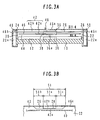
Fig. 3A and 3B are cross sectional views taken along line C-C
during an optical disk record or play by the CD-R/RW drive shown in Fig. 1.
Fig. 4 is a plan view showing an air flow generated on the upper
side of an optical disk during record or play by the CD-R/RW shown in Fig. 1.
Fig. 5 is a plan view, a front view and a side view showing a rectifier
formed on a clamper holder according to another embodiment of the invention.
Fig. 6 is a plan view, a front view and a side view showing a
clamper holder without a rectifier for the comparison purposes.
Fig. 7 is a plan view, a front view and a side view showing a
conventional clamper holder.
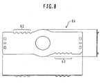
Fig. 8 is a plan view, a front view and a side view showing a rectifier
formed on a clamper holder according to another embodiment of the invention.
Figs. 9A and 9B are a perspective view and a side view showing a
rectifier formed on a clamper holder according to still another embodiment of the
invention.
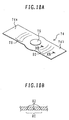
Figs. 10A and 10B are a perspective view and a side view showing
a rectifier formed on a clamper holder according to still another embodiment of
the invention.
Fig. 11 is a perspective view of an air flow guide opening formed in
right and left frame side walls according to another embodiment of the invention.
Fig. 12 is a perspective view of a rectifier formed on a pickup
advance opening of a disk tray.
Figs. 13A and 13B are a perspective view and a cross sectional
view showing the configuration of a rectifier formed on the inner walls of right and
left frame side wall.
BEST MODE FOR CARRYING OUT THE INVENTION
Embodiments of the invention will be described with reference to
the accompanying drawings. Fig. 1 shows a frame 10 constituting a chassis
and a disk tray 12 accommodated in the frame 10 of a CD-R/RW drive capable of
high speed recording/reproducing (an optical disk drive capable of
recording/reproducing a CD-R disk and a CD-RW disk). On the front surface of
the frame 10, a front panel is mounted which is formed with an opening through
which a disk tray 12 is pulled out or pushed in. On the bottom surface of the
frame, a circuit board is mounted, and an outer ornamental cover is mounted on
the side, upper and back surfaces of the frame. The disk tray 12 is slid along a
direction indicated by an arrow A to be pulled out or pushed in by a motor drive.
The disk tray 12 is formed with a recess 14 on which an optical disk is placed, an
opening 16 through which a turn table advances, and an opening 18 through
which an optical pickup advances.
Notches 24 and 26 are formed on upper ends of right and left side
walls 22 and 20 of the frame 10. A damper holder 28 is mounted on the
bottoms of the notches 24 and 26. The notches 24 and 26 are formed deeper
than the thickness of the clamper holder 28. An additional space is formed
above the clamper holder 28.
The clamper holder 28 is made of an elongated metal plate (the
detailed structure is shown in Fig. 2), and opposite end portions along its long
side direction are fixed with screws at center positions of the notches 24 and 26
of the frame 10 along their width direction. The width W1 of the notches 24 and
26 is set sufficiently greater than a length W2 of the clamper holder 28 along its
short side direction. A clamper 30 is rotatively mounted on the central area of
the clamper holder 28 along its long and short side directions. The clamper 30
confronts a lower turntable.
As an optical disk rotates along an arrow B direction, an air flow is
generated above the optical disk surface along the same direction as the arrow B
direction. Plate portions 28a and 28b of the clamper holder 28 are disposed on
both sides of the clamper 30. Repetitive structures 32 and 34 are formed on the
edges of the plate portions on the output side of the air flow, the repetitive
structure having a wave shape as viewed in plan (a straightforward stripe shape
as viewed in elevation) and constituting rectifiers.
The surface of the damper holder in contact with an air flow
generated by the rotation of an optical disk imparts resistance to the air flow
because of viscosity of the air. The resistance against an air flow changes with
the length of the clamper holder surface along the direction of the air flow. Air is
easy to flow in the space having a low resistance. The repetitive structure forms
the space having a low resistance to an air flow and the space having a high
resistance to the air flow, along the direction crossing the rotation direction of a
disk. It can be considered that a turbulent flow is suppressed and a laminar air
flow is generated easily which is in conformity with the surface topology of the
clamper holder.
As shown in Fig. 2, the repetitive structures 32 and 34 have their
outer edge detracted from the outer circumference position of an optical disk by a
predetermined distance D1 (e.g., about 10 mm). It has been confirmed through
experiments that the rectifying effect (disk vibration reducing effect) can be
improved with the retracted outer edge more than the case that the repetitive
structures 32 and 34 are formed to the outer circumference position.
Fig. 3A shows the outline structure at the cross section taken along
line IIIA-IIIA shown in Fig. 1 during an optical disk record or play by the CD-R/RW.
A spindle motor 36 is mounted on the frame 10 in the state that it can be raised
or lowered by a motor drive (usually a tray loading motor is used in common). A
turntable 38 is mounted on the top of a rotary shaft 36a of the spindle motor 36.
As the disk tray 12 is loaded, the spindle motor 36 is raised and the
turntable 38 raises an optical disk 40 (a CD specification disk such as a CD-R
disk and a CD-RW disk) from the disk tray 12 to clamp the disk between the turn
table and clamper 30. As the spindle motor 36 is driven, the optical disk 40
rotates to start a disk record or play with an optical pickup.
In this state, air flow spaces 42 and 44 are formed under and above
the optical disk 40. The clamp holder 28 positions at the middle height of the air
flow space 42 above the optical disk 40. The air flow space 42 above the optical
disk 40 is therefore divided at the position of the clamper holder 28 into: an air
flow space 42a between the lower surface of the clamper holder 28 and the
upper surface of the optical disk 40; and an air flow space 42b between the upper
surface of the clamper holder 28 and the lower surface of an upper plate 46a of
the outer ornamental cover 46.
Ribs 20a and 22a are formed at a proper interval on the outer walls
of the frame side walls 20 and 22. The rib does not exist substantially at the
position higher than the damper holder 28. Spaces 48 and 50 are formed
between the frame side walls 20 and 22 and side wall plates 46b and 46c of the
outer ornamental cover 46.
Fig. 4 shows air flows generated on the upper side of an optical
disk during disk record or play. As an optical disk 40 rotates, air flows are
generated under and above the optical disk along the rotation direction. An air
flow F generated along an upper surface of the optical disk 40 is rectified by the
repetitive structures 32 and 34 having a wave shape as viewed in plan and
formed on the outer edges of the clamper holder 28 on the air flow output side, to
thereby suppress the generation of turbulent air flows. Disk vibrations are
thereby suppressed during high speed rotation. An air flow F generated outside
of the upper surface of the optical disk 40 is divided into upper and lower air flows
by the clamper holder 28. An air flow G1 on the lower side of the clamper holder
28 flows in the space surrounded by the frame side walls 20 and 22. An
air flow G2 on the upper side of the clamper holder 28 also flows in the spaces 48
and 50 between the frame side walls 20 and 22 and the side plates 46b and 46c
of the outer ornamental cover 46, via the notches 24 and 26. The cross section
of the air flow G2 on the upper side of the clamper holder 28 can be broadened
so that a rapid change in the pressure can be reduced to thereby further
suppress disk vibrations during high speed rotation.
Fig. 3B is a cross sectional view taken along line IIIB-IIIB shown in
Fig. 3A. An opening 51 to the spaces 48 and 50 defined by the notches 24 and
26 is a combination of: an opening 51a defined by a left space above the clamper
holder 28; and openings 51b and 51c before and after the opening 51a and
outside of the left spaces above the clamper holder 28. The opening 51 to the
spaces 48 and 50 defined by the notches 24 and 26 is maintained broad in this
way.
The turbulent suppressing effect can be obtained even if there is
only the opening 51a without the openings 51b and 51c (i.e., even if the width of
the notches 24 and 26 is set to approximately the length of the clamper holder 28
along its short side direction) or conversely even if there is only the openings 51b
and 51c without the opening 51a (i.e., even if the upper space of the clamper
holder 28 does not exist), because the air flow can be directed into the spaces 48
and 50.
Fig. 5 shows another configuration of the rectifier formed on the
clamper holder. Repetitive structures 60 and 61 having a wave shape like that
shown in Fig. 2 are formed on a clamper holder 52. In addition, a slit 54 is
formed at the border of each wave, and each divided piece 56 is twisted. The
repetitive structures have therefore a sawtooth shape as viewed both in plan and
in elevation. As shown in the front view, a three-dimensional structure with a
twist is disposed generally along the disk rotation direction, and constitutes a
guide surface directly rectifying an air flow.
Description will be made on the measurement results of the disk
vibration suppressing effect. Table 1 shows the measurement results of disk
vibration angles during a predetermined high speed rotation for a variety of
shapes of the clamper holder. The clamper holder width (a short side length of
a rectangle excepting the central circular expansion portions) was set to 42 mm
for all the clamp holders. A clamp holder without the rectifiers of the repetitive
structures was made as the comparative example.
Fig. 6 shows the clamp holder as the comparative example. The
clamp holder 100 has circular expansion portions 102 in the central area of a
rectangular plate 101.
Fig. 7 shows a clamp holder used conventionally.
Upright ribs 59
are formed on opposing edges along the short side direction over the whole
length along the long side direction. The rectifiers of the repetitive structures are
not formed.
Shape of
Clamper Holder | Disk Vibration Angles |
| | Radial Direction | Jitter Direction | Average |
| Fig. 2 | 0.138 | 0.138 | 0.138 |
| Fig. 5 | 0.107 | 0.107 | 0.107 |
| Fig. 6 | 0.161 | 0.161 | 0.161 |
Fig. 7
(Conventional) | 0.400 | 0.420 | 0.410 |
As understood from Table 1, disk vibrations can be suppressed by
using the clamper holders 28 and 52 shown in Fig. 2 and 5 more than the
clamper holders shown in Figs. 6 and 7. The disk vibration angles are largest
when the clamper holder having upright ribs shown in Fig. 7 is used. It can be
considered that the upright ribs disturb an air flow and generate a large turbulent
air flow. The disk vibration angles are reduced considerably by the flat clamper
holder as the comparative example shown in Fig. 6. It can be considered that
the turbulent air flow is suppressed.
The clamper holders shown in Figs. 2 and 5 further reduce the disk
vibration angles. It can be considered that although in the comparative example
shown in Fig 6, a turbulent air flow still exists in the plane along the disk surface,
the structures shown in Figs 2 and 5 reduce the turbulent air flow. When the
comparison is made between the structures shown in Figs. 2 and 5, the structure
shown in Fig. 5 has smaller disk vibration angles. It can be considered that the
three-dimensional rectifier structure is more effective for turbulent air flow
suppression than the planar rectifier structure.
Experiments were conducted on the influence of the opening 51 by
using a clamp holder without rectifiers shown in Fig. 6.
Table 2 shows the measurement results of disk vibration angles
during a predetermined high speed rotation at different widths of the
notches 24
and 26 formed on the right and left
side walls 22 and 20 of the
frame 10. In
Table 2, "All Openings" means that all openings (51a, 51b and 51c) of the
opening 51 exist in Fig. 3B, and "Only Left Opening" means that only the
opening
51a above the clamp holder is formed without the opening 51b and 51c of the
opening 51 (the width of the
notches 24 and 26 is set to about the length of the
clamp holder 28 along its short side direction).
| Width of Recess | Disk Vibration Angles |
| | Radial Direction | Jitter Direction | Average |
| All Openings | 0.161 | 0.161 | 0.161 |
| Only Left Opening | 0.170 | 0.170 | 0.170 |
As understood from Table 2, the disk vibration angles increase for
the sample of "Only Left Opening". It can be understood that the disk vibrations
can be suppressed by broadening the notches 24 and 26.
Figs. 8, 9 and 10 show other configurations of a rectifier formed on
the clamper holder.
In a clamper holder 64 shown in Fig. 8, each wave constituting
wave-shaped repetitive structures 63 and 64 is bent downward to form the three-dimensional
structure of the repetitive structures both in the plan direction and in
the elevation direction. The effect similar to that of the three-dimensional
structure shown in Fig. 5 can be expected. Although the projection portion as
viewed in plan becomes a convex portion as viewed in front, the projection
portion as viewed in plan may be made a concave portion as viewed in front.
In a clamper holder 66 shown in Fig. 9, repetitive structures 70 and
72 are formed on an elongated metal plate in which concave portions are formed
on plate portions 66a and 66b, the repetitive structures gradually becoming
deeper toward the edge of the metal plate. At the end of the output side of an
air flow, the repetitive structures have a wave shape as viewed in elevation and a
wave surface shape that the end of each wave is continuous with a plane of the
clamper holder 66, and the amplitude of the wave surface gradually lowers at
positions remotely from the edge of the metal plate. A rectifying function by the
three-dimensional structure can be expected. Instead of the concave portion, a
convex portion may be formed.
In a clamper holder 74 shown in Fig. 10A, repetitive structures 78
and 80 are formed on the clamper holder of an elongated metal plate. The
repetitive structures have a plurality of concave stripes (or convex stripes) 82
formed along a disk track direction on the lower surfaces of plate portions 74a
and 74b on both sides of a clamper 76. Fig. 10B is a cross sectional view taken
along line XB-XB shown in Fig. 10A. The rectifying effect by the three-dimensional
structure can be expected. Concave or convex stripes may be
formed on the clamper upper surface.
Fig. 11 shows another configuration of an air flow guide opening
formed on the right and left frame walls. A clamper holder 88 is mounted on the
top edges of the right and left frame side walls 84 and 86. Holes 90, 91, 92 and
93 are formed through the right and left side walls 84 and 86 at positions on both
sides of the mount areas of the clamper holder 88. An outer ornamental cover
(Fig. 3A) is disposed outside of the right and left side walls, with the spaces
constituting the space through which an air flow flows being interposed
therebetween. A portion of an air flow generated above the disk surface during
a disk rotation enters ones of the holes 90 and 92 and exists from the others of
the holes 91 and 93 via the space between the side walls 84 and 86 and the
outer ornamental cover.
Fig. 12 shows an embodiment of rectifiers formed in a pickup
advance or access path opening of a disk tray. Repetitive structures of a wave
shape as viewed in plan are formed on opposing edges 98 and 100 of the pickup
advance opening 96 of the disk tray 94, elongated along a direction crossing a
tangential direction of the disk track, across a recess 97 of a disk tray 94, on
which an optical disk is to be placed.
Figs. 13A and 13B show a configuration of rectifiers formed on the
inner surfaces of the right and left frame side walls. Fig. 13 is a perspective
view and Fig. 13B is a cross sectional view taken along line XIIIB-XIIIB shown in
Fig. 13A. A clamper holder 106 is mounted on the top edges of the right and left
frame side walls 102 and 104. A plurality of convex stripes 108 extending along
a horizontal direction are formed on the inner surfaces of the right and left side
walls 102 and 104 at positions above an optical disk 111 and on both sides of the
clamper holder 106. This three-dimensional structure guides an air flow.
Although the above embodiments are applied to a CD-R/RW drive,
they may be applied to a DVD drive and other optical disk drives.
The present invention has been described in connection with the
preferred embodiments. The invention is not limited only to the above
embodiments. For example, the shape as viewed in plan for changing the
resistance of an air flow and the three-dimensional structure directly guiding an
air flow may be altered in various ways. It will be apparent to those skilled in the
art that other various modifications, improvements, combinations, and the like
can be made.